Note: Descriptions are shown in the official language in which they were submitted.
CA 02995316 2018-02-09
WO
2017/025932 PCT/IB2016/054863
FLOATING ELEMENT FOR REALIZING FLOATING STRUCTURES FOR
SUPPORTING PHOTOVOLTAIC PANELS AND METHOD FOR PRODUCING
SAID FLOATING ELEMENT
FIELD OF THE INVENTION
The present invention relates to the technical field concerning the
realization of
floating structures for supporting photovoltaic panels. In particular, the
present
invention relates to a floating element for realizing floating structures for
supporting photovoltaic panels and to a method for producing said floating
element.
More in detail, the proposed floating element is apt to realize both floating
structures for supporting photovoltaic panels and floating wharves.
DESCRIPTION OF PRIOR ART
It is known that many floating elements connected to each other and a
plurality of
metal rods are used for realizing a floating structure for supporting
photovoltaic
panels.
A floating element of known kind is realized in plastic material, as a unique
body
and is shaped as a cube or a parallelepiped.
Such known floating element is realized by means of blow moulding.
Such technique provides a suitable mould provided with a hole for air
injection and
which can be closed such that, when closed, configures a space therein shaped
as the desired floating element.
In particular, such technique provides the following steps: providing a hollow
cylinder of a plastic material; closing the mould around the hollow cylinder
of
plastic material; injecting air under pressure inside the mould by means of
the hole
1
for injection of the mould, so that the plastic material adheres to the walls
of the
mould so that it gets the shape of the space and remains hollow inside.
In the following, the mould is opened and the floating element is extracted,
which
has a hole at the point where the injection of the air under pressure
occurred,
which is going to be closed by means of a respective plug.
Such technique is expensive and consequently this affects the costs of the
floating
element.
Moreover, since it is a unique body, the thus obtained floating element is
cumbersome. As a consequence, also transport affects the costs of the floating
element, above all considering that a plurality of floating elements is needed
to
realize a floating structure.
This causes another increase in the costs of each floating element.
SUMMARY OF THE INVENTION
Therefore, aim of the present invention is to overcome said drawbacks.
In particular, aim of the present invention is to reduce the transport costs
and the
production costs of the floating element.
The proposed floating element, thanks to fact that it comprises a first
element and
a second element which can be seal-coupled together, can be transported with
said first and second element decoupled and can be assembled near or at the
area of use of the floating element.
2
Date Recue/Date Received 2023-03-20
CA 02995316 2018-02-09
WO 2017/025932
PCT/IB2016/054863
During the transport, this allows to arrange the first and the second element
with
respect to each other such that they take less volume than the volume taken by
the assembled floating element (for example the first element of a floating
element
can be stacked or inserted partially inside a first element of another
floating
element).
Advantageously, the transport costs of the floating element are reduced.
Moreover, thanks to the fact that the proposed floating element is not a
unique
body but it comprises a first element and the second element which can be seal-
coupled together, it is possible to realize the first element and the second
element
by means of the injection moulding technique.
Injection moulding is more diffused than the blow moulding and as a
consequence
it has lower costs. Advantageously this allows to reduce the production costs
of
the floating element as well.
BRIEF DECRIPTION OF THE DRAWINGS
Specific embodiments of the invention will be described in the following
according
to the claims and with reference to the appended drawings, in which:
- figures 1 and 2 show a perspective and side view respectively of the
floating
element object of the present invention:
- figure 3 shows a section view of the floating element along section A-A of
figure
2;
- figure 4 shows an enlarged view of the detail K of figure 3;
- figures 5 and 6 show a perspective view of the first and second element
respectively of the floating element of figure 1;
- figure 7 shows a top view of figure 5;
3
CA 02995316 2018-02-09
WO 2017/025932
PCT/IB2016/054863
- figure 8 shows a bottom view of figure 6;
- figure 9 shows a perspective view of a floating element object of the
present
invention;
- figure 10 shows a perspective view of a preferred embodiment of the
floating
element object of the present invention;
- figure 11 shows an enlarged view of the detail K of figure 10;
- figures 12 and 13 show perspective views respectively of the second
element (4)
of the floating element of figure 10.
DESCRIPTION OF PREFERRED EMBODIMENTS
With reference to the appended drawings, with (1) it is generally indicated a
floating element for realizing floating elements for supporting photovoltaic
panels,
which is object of the present invention.
It is to be precised that the proposed floating element (1) can be used for
example
to realize floating wharves as well.
With reference to the appended drawings, the floating element (1) comprises a
first element (2) which can be obtained by injection moulding, which
configures a
first coupling portion (3), and a second element (4) which can be obtained by
injection moulding, which configures a second coupling portion (5).
The first element (2) and the second element (4) are mutually configured so
that
the first coupling portion (3) and the second coupling portion (5) can be seal-
coupled with respect to each other so that they define a sealed chamber, when
coupled (figures 1 and 2).
Moreover, the floating element (1) comprises connection means (70) for
connecting it to another floating element (1).
4
CA 02995316 2018-02-09
WO 2017/025932
PCT/1B2016/054863
The connection means (70) comprise: a first connection element (71) integral
to
the second element (4), the first connection element (71) comprising a first
portion
(71a) developing from the second element (4) and a first tongue (71b)
developing
from the first portion (71a) and which comprises a first through hole (71c); a
second connection means (72) integral to the first element (2), the second
connection element (72) comprising a second tongue (72a) developing from the
first element (2) and which comprises a second through hole (72b); the first
tongue (71b) and the second tongue (72a) being mutually arranged so that, when
the first element (2) and the second element (4) are coupled, the first
through hole
(71c) is opposed to the second through hole (72b).
Moreover, the first element (2) comprises a first groove (200) which is shaped
complementarily to the first portion (71a) of the first connection element
(71) and
which is arranged so that, when the first element (2) and the second element
(4)
are coupled, the first groove (200) receives the first portion (71a) and they
result in
form-coupling.
Therefore, thanks to their particular shape, in particular thanks to the first
groove
(200) and the first portion (71a) of the first connection means (71), the
connection
means (70) allow: to connect the floating element (1) to another floating
element
(1) and while guaranteeing an optimal coupling between the first portion (2)
and
the second portion (4).
This is particularly important and advantageous in case such floating element
(1)
is used in open sea.
Preferably, the second element (4) comprises a second bottom wall (41) and a
second side wall (42) which rises from the second bottom wall (41) and in
which
5
CA 02995316 2018-02-09
WO 2017/025932
PCT/1132016/054863
the first portion (71a) of the first connection element (71) develops
transversely
(for example perpendicularly) with respect to the second bottom wall (41).
The first tongue (71b) can be transverse to the first portion (71a). The first
tongue
(71b) can be parallel to the second bottom wall (41).
Preferably, the first connection element (71) is a unique body with the second
element (4) and the second connection element (72) is a unique body with the
first
element (2). Advantageously, the connection means (70), the first element (2)
and
the second element (4) can be realized by injection moulding.
It is understood that the connection means (70) can comprise a plurality of
first
connection elements (71) and a plurality of second connection elements (72)
(see
fig. 10). In this way, each floating element (1) can be connected to at least
two
floating elements (1) more.
Preferably, the floating element (1) is such that: the first coupling portion
(3) is
arranged at a first peripheral edge (20) of the first element (2) and
comprises a
first housing (30) comprising in turn a first wall (31) and a second wall (32)
opposed with respect to each other; the second coupling portion (5) is
arranged at
a second peripheral edge (40) of the second element (4) and comprises a third
wall (51). The first housing (30) and the third wall (51) are mutually
configured so
that the first housing (30) can receive the third wall (51) at least partially
(figures 3
and 4).
The first coupling portion (3) can be annular.
The second coupling portion (5) can be annular.
With reference to figure 4, the first housing (30) can be shaped as U. In
particular,
the first housing (30) can comprise a bottom wall (33) which connects the
first wall
6
CA 02995316 2018-02-09
WO 2017/025932
PCT/1B2016/054863
(31) and the second wall (32).
Preferably, the first housing (30) and the third wall (51) are mutually
configured so
that the first housing (30) can receive the third wall (51) as a whole.
Preferably, the second coupling portion (5) comprises a second housing (50)
comprising in turn the third wall (51) and a fourth wall (52) opposed to the
third
wall (51). The second wall (32) and the second housing (50) are mutually
configured so that the second housing (50) can receive the second wall (32) at
least partially.
Advantageously, the coupling between the first element (2) and the second
element (4) is safer from the sealing point of view.
With reference to figure 4, the second housing (50) can be shaped as U. In
particular, the second housing (50) can comprise a bottom wall (55) which
connects the third wall (51) and the fourth wall (52).
Preferably, the second housing (50) and the second wall (32) are mutually
configured so that the second housing (50) can receive the second wall (32) as
a
whole.
Preferably, the second coupling portion (5) comprises a third housing (53)
comprising in turn the third wall (51) and a fifth wall (54) opposed to the
third wall
(51). The first wall (31) and the third housing (53) are mutually configured
so that
the third housing (53) can receive the first wall (31) at least partially.
Advantageously, the coupling between the first element (2) and the second
element (4) is safer from the sealing point of view.
With reference to figure 4, the third housing (53) can be shaped as U. In
particular, the third housing (53) can comprise a bottom wall (55) which
connects
7
the third wall (51) and the fifth wall (52).
Such bottom wall (55) of the third housing (53) can be a unique body with the
bottom wall (5) of the second housing (50) (figure 4).
Preferably, the first wall (31) and the third housing (53) are mutually
configured so
that the third housing (53) can receive the first wall (31) as a whole.
According to the embodiment shown in the figures, the first coupling portion
(3)
can be configured as U and the second coupling portion (5) can be configured
as
M.
The first element (2) and the second element (4) can be mutually configured so
that the first coupling portion (3) and the second coupling portion (5) can be
restraint-coupled to each other.
Possibly, the floating element (1) can comprise glue to stabilize further the
sealing
coupling of the first coupling portion (3) and the second coupling portion
(5).
Preferably, the first element (2) comprises a first bottom wall (21) and a
first side
wall (22) raising from the first bottom wall (21) and which comprises the
first
coupling portion (3). The first side wall (22) is countersunk to define an
angle
greater than 900 with the first bottom wall (21) so that it is possible to
stack the
same first element (2) with a first element (2) of another floating element
(1).
Advantageously, during the transport of many not assembled floating elements
(1)
it is possible to reduce the space taken by the first elements (2) of said
floating
elements (1) by stacking them.
Preferably, the second element (4) comprises a second bottom wall (41) and a
second side wall (42) raising from the second bottom wall (41) and which
8
Date Recue/Date Received 2023-03-20
comprises the second coupling portion (5) (figures 6 and 8). The second side
wall
(42) is countersunk to define an angle greater than 900 with the second bottom
wall (41) so that it is possible to stack the same second element (4) with a
second
element (4) of another floating element (1).
Advantageously, during the transport of many not assembled floating elements
(1)
it is possible to reduce the space taken by the second elements (4) of said
floating
elements (1) by stacking them.
According to the embodiment of the floating element (1) shown in the figures,
the
first element (2) can be configured as a container and the second element (4)
can
be configured as a cover.
As an alternative; the second element (4) can be configured as a container as
well.
In particular, in case the first element (2) and the second element (4) are
equal,
during the transport of many not assembled floating elements (1) it is
possible to
reduce the space taken by said floating elements (1) by stacking the first
elements
(2) and the second elements (4) of said floating elements (1) by stacking
them.
Preferably; when the first element (2) and the second element (4) are coupled
to
each other, the floating element (1) configures a cube or a parallelepiped.
With particular reference to figure 2, the first element (2) can comprise a
groove
(10) (for example shaped as U) configured in the bottom wall (21). Likewise,
the
second element (4) can comprise a groove (11) as well (for example configured
as U) configured in the respective bottom wall (41). Such grooves (10, 11) are
useful to connect more floating elements (1) between to each other to realize
a
9
Date Recue/Date Received 2023-03-20
CA 02995316 2018-02-09
WO 2017/025932 PCT/IB2016/054863
floating structure for supporting photovoltaic panels; in particular, such
grooves
(10, 11) configure housings for the rods used for realizing a floating
structure for
supporting photovoltaic panels.
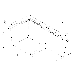
Yet, object of the present invention is a floating structure (100) for
supporting
photovoltaic panels. With reference to figure 9, it comprises a first floating
element
(101) according to one of said embodiments, and a second floating element
(102)
according to one of said embodiments.
In particular, the first floating element (101) and the second floating
element (102)
are mutually arranged so that the first through hole (71c) and the second
through
hole (72b) of the first floating element (101) are opposed to the first
through hole
(71c) and the second through hole (72b) of the second floating element (102).
Moreover, the floating structure (100) comprises a fixing element (103) which
is
configured to cross the first through hole (71c) of the first floating element
(101),
the second through hole (72b) of the first floating element (101), the first
through
hole (71c) of the second floating element (102) and the second through hole
(72b)
of the second floating element (102) and to fix the first floating element
(101) and
the second floating element (102) with respect to each other.
Preferably, the fixing element (103) is configured as a unique body and so
that its
coupling with the first floating element (101) and the second floating element
(102)
is allowed smoothly.
Yet, object of the present invention is the method for producing a floating
element
(1) according to some of said embodiments.
Such method comprises the steps of: producing by means of injection moulding
the first element (2) which configures the first coupling portion (3) and the
second
CA 02995316 2018-02-09
WO 2017/025932
PCT/IB2016/054863
connection element (72); producing by means of injection moulding the second
element (4) which configures the second coupling portion (5) and the first
connection element (71).
Moreover, the method comprises the step of coupling the first element (2) and
the
second element (4) together so that: the first coupling portion (3) and the
second
coupling portion (5) can be seal-coupled and the sealed chamber is formed; the
first through hole (71c) of the first tongue (71b) is opposed to the second
through
hole (72b) of the second tongue (72a); the first groove (200) of the first
element
(2) receives the first portion (71a).
In case the first coupling portion (3) is arranged at a first peripheral edge
(20) of
the first element (2) and comprises a first housing (30) comprising in turn a
first
wall (31) and a second wall (32) opposed with respect to each other and the
second coupling portion (5) is arranged at a second peripheral edge (40) of
the
second element (4) and comprises a third wall (51), the step of coupling the
first
element (2) and the second element (4) with respect to each other comprises
the
steps of injecting glue in the first housing (30) and of introducing the third
wall (51)
in the first housing (30) at least partially.
Advantageously, the coupling is simple and efficient.
In case the second coupling portion (5) comprises a second housing (50)
comprising in turn the third wall (51) and a fourth wall (52) opposed to the
third
wall (51), the step of coupling the first element (2) and the second element
(4) with
respect to each other comprises the steps of injecting glue in the second
housing
(50) and of introducing the second wall (32) in the second housing (50) at
least
partially.
11
CA 02995316 2018-02-09
WO 2017/025932
PCT/1B2016/054863
Advantageously, coupling is more efficient with equal simplicity.
Moreover, in case the second coupling portion (5) comprises a third housing
(53)
comprising in turn the third wall (51) and a fifth wall (54) opposed to the
third wall
(51), the step of coupling the first element (2) and the second element (4)
with
respect to each other comprises the steps of injecting glue in the third
housing
(53) and of introducing the first wall (31) in the third housing (53) at least
partially.
Preferably, the step of producing the first element (2) occurs in a first
production
area, the step of producing the second element (4) occurs in a second
production
area, and the step of coupling the first element (2) with the second element
(4)
occurs near or at an area of use of the floating element (1).
Advantageously the floating element (1) can be transported in not assembled
form
and this reduces the transport costs of the floating element (1).
= Preferably, the first production area and the second production area are
the same.