Note: Descriptions are shown in the official language in which they were submitted.
CA 02995483 2018-02-12
WO 2017/031441
PCT/US2016/047813
TOP DRIVE TORQUE MEASUREMENT DEVICE
BACKGROUND OF THE INVENTION
Field of the Invention
paw Embodiments of the present invention generally relate to a method and
apparatus for measuring torque in a top drive system.
Description of the Related Art
[0002] A wellbore is formed to access hydrocarbon-bearing formations (e.g.,
crude oil and/or natural gas) or for geothermal power generation by the use of
drilling. Drilling is accomplished by utilizing a drill bit that is mounted on
the end of
a drill string. To drill within the wellbore to a predetermined depth, the
drill string is
often rotated by a top drive on a surface rig. After drilling to a
predetermined
depth, the drill string and drill bit are removed and a section of casing is
lowered
into the wellbore. An annulus is thus formed between the string of casing and
the
formation. The casing string is hung from the wellhead. A cementing operation
is
then conducted in order to fill the annulus with cement. The casing string is
cemented into the wellbore by circulating cement into the annulus defined
between the outer wall of the casing and the borehole. The combination of
cement
and casing strengthens the wellbore and facilitates the isolation of certain
areas of
the formation behind the casing for the production of hydrocarbons.
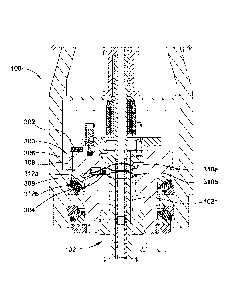
[0003] Top drives are equipped with a motor for rotating the drill string.
The
quill of the top drive is typically threaded for connection to an upper end of
the drill
pipe in order to transmit torque to the drill string. It is important to
accurately
measure the torque transmitted by the top drive to ensure proper engagement
between the quill of the top drive and the drill string. Furthermore, the
torque must
be accurately measured to prevent overloading the drill string, drill head,
and/or
drill bit.
[0004] Therefore, there is a need for an apparatus and method for
accurately
measuring the torque provided by the top drive system.
1
SUBSTITUTE SHEET (RULE 26)
CA 02995483 2018-02-12
WO 2017/031441 PCT/US2016/047813
SUMMARY OF THE INVENTION
[0005] In one embodiment, a top drive system for use with a tool for
handling
tubulars on a drilling rig includes a motor unit; a coupling unit that
transfers torque
to the tool; a torque measurement device (TMD) coupled to at least one of the
motor unit, the tool, or the coupling unit, wherein the TMD includes a sensing
member coupled to an evaluation unit, wherein the sensing member is configured
to measure a magnetostrictive effect and the evaluation unit is configured to
calculate a magnitude of the torque reaction force based on the
magnetostrictive
effect.
BRIEF DESCRIPTION OF THE DRAWINGS
[0006] So that the manner in which the above recited features of the
present
invention can be understood in detail, a more particular description of the
invention, briefly summarized above, may be had by reference to embodiments,
some of which are illustrated in the appended drawings. It is to be noted,
however, that the appended drawings illustrate only typical embodiments of
this
invention and are therefore not to be considered limiting of its scope, for
the
invention may admit to other equally effective embodiments.
[0007] Figure 1 illustrates a motor unit of a top drive system, according
to one
embodiment of the present disclosure.
[0008] Figure 2A is a side-view of the motor unit coupled to a rail
bracket.
[0009] Figure 2B is a top-view of the motor unit coupled to the rail
bracket.
[0010] Figure 3A is an enlarged view of the motor unit having a torque
measuring device according to one embodiment of the present disclosure in a
first
position.
[0011] Figure 3B is an enlarged view of the motor unit having the torque
measuring device of Figure 3A in a second position.
[0012] Figure 4 is an enlarged view of the motor unit having a torque
measuring device according to another embodiment of the present disclosure.
2
CA 02995483 2018-02-12
WO 2017/031441 PCT/US2016/047813
[0013] Figure 5 is an enlarged view of the motor unit having a torque
measuring device according to yet another embodiment of the present
disclosure.
[0014] Figure 6 illustrates an alternative motor unit of a top drive
system,
according to one embodiment of the present disclosure.
[0015] Figure 7 is an enlarged view of the alternative motor unit having a
torque measuring device according to another embodiment of the present
disclosure.
[0016] Figure 8 is an enlarged view of the alternative motor unit having a
torque measuring device according to yet another embodiment of the present
disclosure.
[0017] Figure 9 is an enlarged view of the alternative motor unit having a
torque measuring device according to yet another embodiment of the present
disclosure.
[0018] Figure 10 illustrates a load transfer assembly of a tong assembly
having
a torque measuring device according to one embodiment of the present
disclosure.
DETAILED DESCRIPTION
[0019] While the foregoing is directed to embodiments of the present
invention,
other and further embodiments of the invention may be devised without
departing
from the basic scope thereof, and the scope thereof is determined by the
claims
that follow.
[0020] Figure 1 illustrates a motor unit 100 of a top drive system. An
exemplary top drive system is disclosed in U.S. Patent Application Number
62/107,599, which is hereby fully incorporated by reference, in particular,
paragraphs [0045]-[0058], [0063], [0086]-[0091], [0094]-[0096], and [0139]-
[0142]
and Figures 2A, 3, 4F-4K, 9A, and 9B.
[0021] The motor unit 100 is connected to a tool 102, as shown in Figures 1-
5.
3
CA 02995483 2018-02-12
WO 2017/031441 PCT/US2016/047813
The tool 102 is configured for attachment to a casing, drilling, and/or
cementing
string. The motor unit 100 includes drive motors 104, a drive body 106, a
swivel,
a rail bracket 110 (Figures 2A and 2B), and motor gears 114 (Figure 2A).
[0022] In one embodiment, the motor unit 100 is attached to a coupling
unit.
The coupling unit transfers torque and load from the motor unit 100 to the
tool
102. The coupling unit may include a drive gear 108 and a thread compensator
112. The drive gear 108 includes a bore therethrough and comprises an inner
coupling mechanism that can connect one of several tools 102, such as a
drilling
tool exemplarily shown in Figure 1. The compensator 112 is configured to
remove
strain on threads during make-up and break out of connections. The drive gear
108 is rotatable relative to the drive body 106. For example, an up-thrust
bearing
116 and a down-thrust bearing 118 allow the drive gear 108 to rotate relative
to
the drive body 106. The drive motors 104 are operable to torsionally drive
respective motor gears 114 via a shaft 115. The motor gears 114 are meshed
with
the drive gear 108 for torsional driving thereof.
[0023] The rail bracket 110 includes upper bridges 122a and 122b, lower
bridges 124a and 124b, and a trolley 120 configured to counteract torque
applied
to the tool 102. The drive body 106 is coupled to the rail bracket 110, as
shown in
Figures 2A and 2B. In one embodiment, an upper end of the drive body 106 is
fastened to the trolley 120 via the upper bridges 122a and 122b. The trolley
120
and the upper bridges 122a,b thereby torsionally restrain the upper end of the
drive body 106 while allowing vertical movement of the motor unit 100. In one
embodiment, a lower end of the drive body 106 is also coupled to the rail
bracket
110, such as by fastening the drive body 106 to the trolley 120 via the lower
bridges 124a and 124b. The trolley 120 and the lower bridges 124a,b thereby
torsionally restrain the lower end of the drive body 106 while allowing
vertical
movement of the motor unit 100. The trolley 120 is movable vertically along a
rail
to raise and lower the casing, drilling, and/or cementing strings attached to
the
tool 102.
[0024] Referring again to Figure 1, the tool 102 may include a head 102h, a
neck 102n, a lifting shoulder 102s, and a torso 102r. In one embodiment, the
4
CA 02995483 2018-02-12
WO 2017/031441 PCT/US2016/047813
compensator 112 includes a lock ring 113 having retractable lock pins, which
when extended, are configured to engage respective slots formed in the head
102h of the tool 102, thereby connecting the lock ring 113 to the tool 102 and
allowing a lift up via the compensator 112. Alternatively, a rotating latch
ring may
connect the lock ring 113 to the tool 102. The tool 102 is further secured
relative
to the drive body 106 by engagement with a bayonet profile 108b and a locking
profile 108k on the drive gear 108 with respective profiles on the tool 102.
As a
result, the tool 102 is longitudinally and torsionally connected to the drive
gear
108, thereby forming a top drive.
[0025] The motor unit 100 includes at least one torque measurement device
for measuring a torque exerted on the motor unit 100. The torque measurement
device may be disposed at any appropriate location on the motor unit 100 to
increase accuracy and response time and decrease the influence of a weight
load
on the tool 102.
[0026] In one embodiment, the motor unit 100 includes a torque measurement
device (TMD) 200 on the rail bracket 110, as shown in Figures 2A and 2B. For
example, a respective TMD 200 is disposed on at least one of the bridges
122a,b
and 124a,b. In one embodiment, two TMDs 200 are used on lower respective
bridges 124a,b. In another embodiment, four TMDs 200 are disposed on
respective upper and lower bridges 122a,b and 124a,b. In this embodiment, the
TMDs are mounted on the upper and lower bridges to enhance measurement
accuracy and compensation. Each TMD 200 may be disposed on an outer-facing
surface (as shown in Figures 2A and 2B) or an inner-facing surface of each
respective bridge. The TMD 200 includes any appropriate sensor for measuring
torque. For example, the TMD 200 includes sensing members, such as any
appropriate load cell for measuring strain and compression. The load cells may
be appropriately positioned on the bridges 122a,b and 124a,b to measure the
torque exerted on the motor unit 100. The TMD 200 may be connected to an
evaluation unit, such as a processor, for interpreting torque measurements.
For
example, when torque is exerted on the motor unit 100, the torque changes an
electrical resistance of the load cells in proportion to the torque. The
change in
CA 02995483 2018-02-12
WO 2017/031441 PCT/US2016/047813
electrical resistance of the load cell is transmitted to the evaluation unit,
where the
change is calibrated to correspond to a torque exerted on the tool 102. The
upper
and lower bridges 122a,b and 124a,b may tilt due to vertical or horizontal
movement of the motor unit 100 relative to the bracket 110. The tilting of the
bridges 122a,b and 124a,b changes the electrical resistance of the load cells
in
proportion to a tilting angle of the bridges 122a,b and 124a,b causing an
incorrect
torque measurement by the evaluation unit. The tilting angle of the bridges
122a,b, and 124a,b may be measured relative to the motor unit 100 and/or the
bracket 110. The measured tilting angle and change in electrical resistance of
the
load cell is transmitted to the evaluation unit, where the change in
electrical
resistance and measured tilting angle are calibrated to correspond to a torque
exerted on the tool 102. Alternatively, load measuring bolts may be used to
connect the bridges 122a,b and 124a,b to the bracket 110 and motor unit 100.
The load measuring bolts may measure the load exerted on the bridges 122a,b,
and 124a,b due to vertical or horizontal movement of the motor unit 100
relative to
the bracket 110. The measured load is transmitted to the evaluation unit with
the
change in electrical resistance of the load cell, where the change in
electrical
resistance and measured load are calibrated to correspond to a torque exerted
on
the tool 102.
[0027] Figures 3A and 3B show an enlarged view of the motor unit 100 having
a torque measurement device (TMD) 300, according to another embodiment of
the disclosure. As shown in Figure 3A, the TMD 300 is disposed on the drive
gear
108. The TMD 300 includes an evaluation unit 302, such as a processor,
connected to a sensing member 304 via cable 306. Alternatively, the evaluation
unit 302 may communicate with the sensing member 304 wirelessly. The TMD
300 may also include a positioning device 308 having a positioning shaft 314
(Figure 3B) configured to move the sensing member 304 between a retracted
position and an extended position. For example, the sensing member 304 is in
the retracted position during the installation of the tool 102. After
connecting the
tool 102 to the motor unit 100, the positioning shaft 314 moves the sensing
member 304 towards the extended position. The TMD 300 includes any
appropriate sensing member 304 for high precision, contactless torque
6
CA 02995483 2018-02-12
WO 2017/031441 PCT/US2016/047813
measurements. For example, the sensing member 304 is configured to measure
a magnetostrictive effect on the tool 102.
[0028] In one embodiment, the sensing member 304 includes at least one
inverse magnetostrictive sensor. At least a portion of the tool 102 includes
ferromagnetic material. For example, the tool includes magnetized areas 310a
and 310b. As shown, the magnetized areas 310a,b are disposed on the neck
102n of the tool 102. The magnetized areas 310a,b are axially aligned with a
corresponding number of sensors in the sensing member 304, such as inverse
magnetostrictive sensors 312a and 312b. As shown, the magnetized areas
310a,b and the sensors 312a,b are laterally spaced apart. When the tool 102 is
subject to torque, a strain on an outer surface of the tool 102 changes the
dimensions of the magnetized areas 310a,b, thereby changing a magnetic field
between the magnetized areas 310a,b and the sensors 312a,b. The inverse
magnetostrictive sensors 312a,b are configured to measure the magnetic field
changes in real time. Thereafter, the sensing member 304 transmits the
magnetic
field measurements to the evaluation unit 302 via the cable 306. The
evaluation
unit 302 calculates the magnitude of torque exerted on the magnetized areas
310a,b of the tool 102 based on the change in the magnetic field measured by
the
sensors 312a,b.
[0029] In another embodiment, the sensing member 304 includes an
anisotropic magnetostrictive sensor. In this embodiment, the sensing member
304 is axially aligned with a magnetized area, such as area 310a or 310b. In
operation, torque exerted on the tool 102 may cause a compressive stress
and/or
tensile stress on the magnetized area. The permeability for magnetization in a
direction of compressive stress is different in comparison to magnetization in
a
direction of tensile stress. The anisotropic magnetostrictive sensor in the
sensing
member 304 is configured to measure the difference in permeability and
transmit
the measurements to the evaluation unit 302 via the cable 306. Thereafter, the
evaluation unit 302 calculates the magnitude of torque exerted on the
magnetized
area of the tool 102 based on the difference in permeability.
[0030] As shown in Figure 3B, the TMD 300 may be disposed on the drive
7
CA 02995483 2018-02-12
WO 2017/031441 PCT/US2016/047813
body 106. For example, the TMD 300 is attached to a lower end of the drive
body
106. As shown, the magnetized areas 310a,b are disposed on the torso 102r of
the tool 102. In one embodiment, the sensing member 304 having the inverse
magnetostrictive sensors 312a,b is axially aligned with corresponding
magnetized
areas 310a,b for measuring the change in magnetic field therebetween. In
another embodiment, the sensing member 304 having the anisotropic
magnetostrictive sensor is axially aligned with a corresponding magnetized
area
310a or 310b for measuring permeability in compression and tension.
[0031] Figure
4 shows an enlarged view of the motor unit 100 having a torque
measurement device (TMD) 400, according to another embodiment of the
disclosure. As shown, the TMD 400 is disposed on the neck 102n of the tool
102.
The TMD 400 may also, or alternatively, be disposed on the torso 102r of the
tool
102. The
TMD 400 includes any appropriate sensor for high precision,
contactless torque measurements, such as an optical sensor. The TMD 400
includes an evaluation unit 402, such as a processor, connected to a coupling
member 408 via a cable 409. Alternatively, the evaluation unit 402 may
communicate with the coupling member 408 wirelessly. The drive gear 108
includes a device 410 for transmitting energy and data with the coupling
member
408. The coupling member 408 is configured to wirelessly and continuously
transfer measurements processed by the evaluation unit 402 to the device 410.
Power transmission from the device 410 to the coupling member 408 is performed
by using induction. Alternatively, power and data transmission between the
device
410 and the coupling member 408 is performed via cables through the swivel.
Alternatively, power may be generated directly at the tool 102 or stored for
use in
a battery or an electrical accumulator.
[0032] The
evaluation unit 402 is also coupled to an optical transmitter/receiver
404 via a cable 406. Alternatively, the evaluation unit 402 may communicate
with
the optical transmitter/receiver 404 wirelessly. Alternatively, a separate
optical
transmitter and receiver are provided. The optical transmitter/receiver 404 is
coupled to an upper grid plate 412 via a first optical fiber cable 414 and a
lower
grid plate 416 via a second optical fiber cable 418. The upper and lower grid
8
CA 02995483 2018-02-12
WO 2017/031441 PCT/US2016/047813
plates 412, 416 may be disposed on the neck 102 and/or the torso 102r of the
tool
102. The optical transmitter/receiver 404 is configured to transmit light onto
each
of the upper and lower grid plates 412, 416 via respective first and second
optical
fiber cables 414, 418. The
light is transmitted back to the optical
transmitter/receiver 404 via the same or additional respective fiber cables
412,
416. Under zero torque conditions, the light transmissions from the upper and
lower grid plates 412, 416 are in phase with each other. When torque is
applied
to the tool 102, the reflected light from the upper and lower grid plates 412,
416 is
modulated. Phase
change measurements are received by the optical
transmitter/receiver 404 and transmitted to the evaluation unit 402, where the
magnitude of torque exerted on the tool 102 is calculated based on the phase
difference.
[0033] Figure
5 shows an enlarged view of the motor unit 100 having a torque
measurement device (TMD) 500, according to another embodiment of the
disclosure. As shown, the TMD 500 is disposed on the neck 102n of the tool
102.
The TMD 500 may also, or alternatively, be disposed on the torso 102r of the
tool
102. The
TMD 500 includes any appropriate sensor for high precision,
contactless torque measurements. The TMD 500 includes an evaluation unit 502,
such as a processor, connected to a coupling member 508 via cable 509.
Alternatively, the evaluation unit 502 may communicate with the coupling
member
508 wirelessly. The drive gear 108 includes a device 510 for transmitting
energy
and data with the coupling member 508. For example, the coupling member 508
is configured to wirelessly and continuously transfer measurements processed
by
the evaluation unit 502 to the device 510. Power transmission from the device
510 to the coupling member 508 is performed by using induction. Alternatively,
power and data transmission between the device 510 and the coupling member
508 is performed via cables through the swivel. Alternatively, power may be
generated directly at the tool 102 or stored for use in a battery or
electrical
accumulator.
[0034] The
evaluation unit 502 is also coupled to a sensing member 504 via
cable 506. Alternatively, the evaluation unit 502 may communicate with the
9
CA 02995483 2018-02-12
WO 2017/031441 PCT/US2016/047813
sensing member 504 wirelessly. In one embodiment, the sensing member 504
includes a surface acoustic wave (SAW) sensor. In one embodiment, the SAW
sensor includes a piezoelectric substrate having an input transducer separated
by
a distance from an output transducer. A surface wave propagates between the
input and output transducers on the piezoelectric substrate. Under zero torque
conditions, the surface wave has a phase associated with a zero torque applied
to
the tool 102. When torque is applied to the tool 102, the distance between the
input and output transducers changes and the surface wave exhibits a phase
different from the zero torque phase. The phase measurements are transmitted
from the sensing member 504 to the evaluation unit 502, where the magnitude of
the torque exerted on the tool 102 is calculated based on the phase
difference. In
another embodiment, the SAW sensor is used as a resonant element. For
example, the SAW sensor includes the piezoelectric substrate having spaced
apart interdigital electrodes. When zero torque is applied to the tool 102, a
surface wave with a baseline resonant frequency propagates on the substrate
between the electrodes. When torque is applied to the tool 102, the spacing
between the electrodes changes, thereby changing the resonant frequency of the
surface wave between the electrodes. If used as an amplifier feedback, the
resonant frequency and the distance between the electrodes can be measured
and evaluated.
[0035] In another embodiment, the sensing member 504 includes
strain/compression load cells as described herein. The load cells may be
appropriately positioned on the neck 102n and/or the torso 102r in order to
accurately measure the torque and/or load exerted on the tool 102. The load
cells
may be connected to the evaluation unit 502 for interpreting gathered
measurements. For example, when torque and/or load is exerted on the tool 102,
the strain changes an electrical resistance of the load cells in proportion to
the
torque and/or load. The change in electrical resistance of the load cell is
transmitted to the evaluation unit 502, where the torque and/or load exerted
on
the tool 102 is calculated based on the change in electrical resistance.
[0036] Figure 6 illustrates a motor unit 600 of a top drive system. The
motor
CA 02995483 2018-02-12
WO 2017/031441 PCT/US2016/047813
unit 600 is connected to a tool 602, as shown in Figures 6-9. The tool 602 is
configured for attachment to a casing, drilling, and/or cementing string. The
motor
unit 600 includes drive motors 604, a drive body 606, and a drive gear 608.
The
drive body 606 may include a lower tubular portion with a bore therethrough
and
openings at respective longitudinal ends thereof. The drive gear 608 may be
disposed in an inner cavity of the drive body 606.
[0037] In one embodiment, the motor unit 600 is attached to a coupling
unit.
The coupling unit transfers torque and load from the motor unit 600 to the
tool
602. The coupling unit may be at least partially disposed in the lower tubular
portion of the drive body 606. The coupling unit may include a shaft 609, a
housing 611, and a thread compensator 612. The shaft 609 may include a neck
609n. The shaft 609 may have couplings, such as threaded couplings, formed at
a
lower longitudinal end thereof on an outer surface of the shaft 609 that can
connect to the housing 611 and on an inner surface of the shaft 609 that can
connect one of several tools 602, such as a drilling tool exemplarily shown in
Figure 6. The housing 611 may be tubular and have a longitudinal bore
therethrough. The housing 611 may have a coupling, such as a threaded
coupling, formed at a longitudinal end thereof for connection to the
corresponding
coupling of the shaft 609. The housing 611 may have a shoulder 611s located at
a
lower longitudinal end thereof. The compensator 612 is configured to remove
strain on threads during make-up and break out of connections. The drive gear
608 may be coupled to and disposed on an outside of the shaft 609. The drive
gear 608 may be integrally connected to the shaft 609. The drive gear 608 and
shaft 609 are rotatable relative to the drive body 606. For example, thrust
bearings
616, 617, 618 allow the drive gear 608 and shaft 609 to rotate relative to the
drive
body 606. The drive motors 604 are operable to torsionally drive respective
motor
gears (not shown) via a shaft (not shown). The motor gears are meshed with the
drive gear 608 for torsional driving thereof.
[0038] The tool 602 may include a head 602h and a torso 602r. In one
embodiment, the compensator 612 includes a lock ring 613 having retractable
lock pins, which when extended, are configured to engage respective slots
formed
11
CA 02995483 2018-02-12
WO 2017/031441 PCT/US2016/047813
in the head 602h of the tool 602, thereby connecting the lock ring 613 to the
tool
602 and allowing a lift up via the compensator 612. Alternatively, a rotating
latch
ring may connect the lock ring 613 to the tool 602. The head 602h rests on the
shoulder 611s of the housing, transferring the load of the tool 602 to the
drive
gear 608 through the shaft 609 via the compensator 612 and housing 611. The
housing 611 may include a locking profile on an inner surface thereof for
engagement with a respective profile on the tool head 602h. As a result,
torque
may be transferred from the drive gear 608 to the tool 602 via the couplings
between the shaft 609 and the housing 611 and via the profiles in the housing
611
and the head 602h. As a result, the tool 602 is longitudinally and torsionally
connected to the drive gear 608, thereby forming a top drive.
[0039] The motor unit 600 includes at least one torque measurement device
for
measuring a torque exerted on the motor unit 600. The torque measurement
device may be disposed at any appropriate location on the motor unit 600 to
increase accuracy and response time and decrease the influence of a weight
load
on the tool 602.
[0040] In one embodiment, the motor unit 600 includes the torque
measurement device (TMD) 200, as shown in Fig. 2A and 2B. Motor unit 600 may
replace the motor unit 100. Motor unit 600 may include the rail bracket 110
and
bridges 122a,b, 124a,b, as shown in Figures 2A and 2B. For example, a
respective TMD 200 is disposed on at least one of the bridges 122a,b and
124a,b.
In one embodiment, two TMDs 200 are used on lower respective bridges 124a,b.
In another embodiment, four TMDs 200 are disposed on respective upper and
lower bridges 122a,b and 124a,b. In this embodiment, the TMDs are mounted on
the upper and lower bridges to enhance measurement accuracy and
compensation. Each TMD 200 may be disposed on an outer-facing surface (as
shown in Figures 2A and 2B) or an inner-facing surface of each respective
bridge.
The TMD 200 includes any appropriate sensor for measuring torque. For
example, the TMD 200 includes sensing members, such as any appropriate load
cell for measuring strain and compression. The load cells may be appropriately
positioned on the bridges 122a,b and 124a,b to measure the torque exerted on
12
CA 02995483 2018-02-12
WO 2017/031441 PCT/US2016/047813
the motor unit 600. The TMD 200 may be connected to an evaluation unit, such
as a processor, for interpreting torque measurements. For example, when torque
is exerted on the motor unit 600, the torque changes an electrical resistance
of the
load cells in proportion to the torque. The change in electrical resistance of
the
load cell is transmitted to the evaluation unit, where the change is
calibrated to
correspond to a torque exerted on the tool 602. The upper and lower bridges
122a,b and 124a,b may tilt due to vertical or horizontal movement of the motor
unit 600 relative to the bracket 110. The tilting of the bridges 122a,b and
124a,b
causes additional loading of the bridges that increase the measured tensional
strain and therefore changes the electrical resistance of the load cells in
proportion to a tilting angle of the bridges 122a,b and 124a,b causing an
incorrect
torque measurement by the evaluation unit. The tilting angle of the bridges
122a,b, and 124a,b may be measured relative to the motor unit 600 and/or the
bracket 110. The measured tilting angle and change in electrical resistance of
the
load cell is transmitted to the evaluation unit, where the change in
electrical
resistance and measured tilting angle are calibrated to correspond to a torque
exerted on the tool 602. Alternatively, load measuring bolts may be used to
connect the bridges 122a,b and 124a,b to the bracket 110 and/or motor unit
600.
The load measuring bolts may measure the load exerted on the bridges 122a,b,
and 124a,b due to vertical or horizontal movement of the motor unit 600
relative
to the bracket 110. The measured load is transmitted to the evaluation unit
with
the change in electrical resistance of the load cell, where the change in
electrical
resistance and measured load are calibrated to correspond to a torque exerted
on
the tool 602.
[0041] In one embodiment, the motor unit 600 includes a torque measurement
device (TMD) 700, as shown in Figure 7. Figure 7 shows an enlarged view of the
motor unit 600. The TMD 700 is disposed on the lower tubular portion of the
drive
body 606. The TMD 700 may be similar to the TMD 300. The TMD 700 includes
an evaluation unit 702, such as a processor, connected to a sensing member 704
via cable 706. Alternatively, the evaluation unit 702 may communicate with the
sensing member 704 wirelessly. The TMD 700 may also include a positioning
device 708 having a positioning shaft configured to move the sensing member
13
CA 02995483 2018-02-12
WO 2017/031441 PCT/US2016/047813
704 between a retracted position and an extended position. For example, the
sensing member 704 is in the extended position during the operation of the
motor
unit 600 and/or the tool 602. The positioning shaft moves the sensing member
704 towards the retracted position during non-operational times of the motor
unit
600 and/or the tool 602. The TMD 700 includes any appropriate sensing member
704 for high precision, contactless torque measurements. For example, the
sensing member 704 is configured to measure a magnetostrictive effect on the
shaft 609.
[0042] In one embodiment, the sensing member 704 includes at least one
inverse magnetostrictive sensor. At least a portion of the tool 602 includes
ferromagnetic material. For example, the tool includes magnetized areas 710a
and 710b. As shown, the magnetized areas 710a,b are disposed on the neck
609n of the shaft 609. The magnetized areas 710a,b are axially aligned with a
corresponding number of sensors in the sensing member 704, such as inverse
magnetostrictive sensors 712a and 712b. As shown, the magnetized areas 710a,b
and the sensors 712a,b are laterally spaced apart. When the shaft 609 is
subject
to torque, a strain on an outer surface of the shaft 609 changes the
dimensions of
the magnetized areas 710a,b thereby changing a magnetic field between the
magnetized areas 710a,b and the sensors 712a,b. The inverse magnetostrictive
sensors 712a,b are configured to measure the magnetic field changes in real
time.
Thereafter, the sensing member 704 transmits the magnetic field measurements
to the evaluation unit 702 via the cable 706. The evaluation unit 702
calculates the
magnitude of the torque exerted on the magnetized areas 710a,b of the shaft
609
based on the change in the magnetic field measured by the sensors 712a,b.
[0043] In another embodiment, the sensing member 704 includes an
anisotropic magnetostrictive sensor. In this embodiment, the sensing member
704
is axially aligned with a magnetized area, such as area 710a or 710b. In
operation, torque exerted on the shaft 609 may cause a compressive stress
and/or tensile stress on the magnetized area. The permeability for
magnetization
in a direction of compressive stress is different in comparison to
magnetization in
a direction of tensile stress. The anisotropic magnetostrictive sensor in the
14
CA 02995483 2018-02-12
WO 2017/031441 PCT/US2016/047813
sensing member 704 is configured to measure the difference in permeability and
transmit the measurements to the evaluation unit 702 via the cable 706.
Thereafter, the evaluation unit 702 calculates the magnitude of torque exerted
on
the magnetized area of the shaft 609 based on the difference in permeability.
[0044] Figure 8 shows an enlarged view of the motor unit 600 having a
torque
measurement device (TMD) 800, according to another embodiment of the
disclosure. The TMD 800 may be similar to the TMD 400. As shown, the TMD
800 is disposed on the neck 609n of the shaft 609. The TMD 800 may also, or
alternatively, be disposed on the torso 602r of the tool 602. The TMD 800
includes any appropriate sensor for high precision, contactless torque
measurements, such as an optical sensor. The TMD 800 includes an evaluation
unit 802, such as a processor, connected to a coupling member 808 via a cable
809. Alternatively, the evaluation unit 802 may communicate with the coupling
member 808 wirelessly. The drive body 606 includes a device 810 for
transmitting
energy and data with the coupling member 808. The coupling member 808 is
configured to wirelessly and continuously transfer measurements processed by
the evaluation unit 802 to the device 810. Power transmission from the device
810 to the coupling member 808 is performed by using induction. Alternatively,
power and data transmission between the device 810 and the coupling member
808 is performed via cables through a swivel of the motor unit 600.
Alternatively,
power may be generated directly at the tool 602 or stored for use in a battery
or
electrical accumulator.
[0045] The evaluation unit 802 is also coupled to an optical
transmitter/receiver
804 via a cable 806. Alternatively, the evaluation unit 802 may communicate
with
the optical transmitter/receiver 804 wirelessly. Alternatively, a separate
optical
transmitter and receiver are provided. The optical transmitter/receiver 804 is
coupled to an upper grid plate 812 via a first optical fiber cable 814 and a
lower
grid plate 816 via a second optical fiber cable 818. The upper and lower grid
plates 812, 816 may be disposed on the neck 609n of the shaft 609 and/or the
torso 602r of the tool 602. The optical transmitter/receiver 804 is configured
to
transmit light onto each of the upper and lower grid plates 812, 816 via
respective
CA 02995483 2018-02-12
WO 2017/031441 PCT/US2016/047813
first and second optical fiber cables 814, 818. The light is transmitted back
to the
optical transmitter/receiver 804 via the same or additional respective fiber
cables
812, 816. Under zero torque conditions, the light transmissions from the upper
and lower grid plates 812, 816 are in phase with each other. When torque is
applied to the shaft 609 and tool 602, the reflected light from the upper and
lower
grid plates 812, 816 is modulated. Phase change measurements are received by
the optical transmitter/receiver 804 and transmitted to the evaluation unit
802,
where the magnitude of torque exerted on the shaft 609 and/or tool 602 is
calculated based on the phase difference.
[0046] Figure 9 shows an enlarged view of the motor unit 600 having a
torque
measurement device (TMD) 900, according to another embodiment of the
disclosure. The TMD 900 may be similar to the TMD 500. As shown, the TMD
900 is disposed on the neck 609n of the shaft 609. The TMD 900 may also, or
alternatively, be disposed on the torso 602r of the tool 602. The TMD 900
includes any appropriate sensor for high precision, contactless torque
measurements. The TMD 900 includes an evaluation unit 902, such as a
processor, connected to a coupling member 908 via cable 909. Alternatively,
the
evaluation unit 902 may communicate with the coupling member 908 wirelessly.
The drive body 606 includes a device 910 for transmitting energy and data with
the coupling member 908. For example, the coupling member 908 is configured
to wirelessly and continuously transfer measurements processed by the
evaluation unit 902 to the device 910. Power transmission from the device 910
to
the coupling member 908 is performed by using induction. Alternatively, power
and data transmission between the device 910 and the coupling member 908 is
performed via cables through the swivel. Alternatively, power may be generated
directly at the tool 602 or stored for use in a battery or electrical
accumulator.
[0047] The evaluation unit 902 is also coupled to a sensing member 904 via
cable 906. Alternatively, the evaluation unit 902 may communicate with the
sensing member 904 wirelessly. In one embodiment, the sensing member 904
includes a surface acoustic wave (SAW) sensor. In one embodiment, the SAW
sensor includes a piezoelectric substrate having an input transducer separated
by
16
CA 02995483 2018-02-12
WO 2017/031441 PCT/US2016/047813
a distance from an output transducer. A surface wave propagates between the
input and output transducers on the piezoelectric substrate. Under zero torque
conditions, the surface wave has a phase associated with a zero torque applied
to
the shaft 609 and tool 602. When torque is applied to the shaft 609 and tool
602,
the distance between the input and output transducers changes and the surface
wave exhibits a phase different from the zero torque phase. The phase
measurements are transmitted from the sensing member 904 to the evaluation
unit 902, where the magnitude of the torque exerted on the shaft 609 and/or
the
tool 602 is calculated based on the phase difference. In another embodiment,
the
SAW sensor is used as a resonant element. For example, the SAW sensor
includes the piezoelectric substrate having spaced apart interdigital
electrodes.
When zero torque is applied to the shaft 609 and the tool 602, a surface wave
with
a baseline resonant frequency propagates on the substrate between the
electrodes. When torque is applied to the shaft 609 and the tool 602, the
spacing
between the electrodes changes, thereby changing the resonant frequency of the
surface wave between the electrodes. If used as an amplifier feedback, the
resonant frequency and the distance between the electrodes can be measured
and evaluated.
[0048] In another embodiment, the sensing member 904 includes
strain/compression load cells as described herein. The load cells may be
appropriately positioned on the shaft 609 and/or the torso 602r in order to
accurately measure the torque exerted on the shaft 609 and/or the tool 602.
The
load cells may be connected to the evaluation unit 902 for interpreting
gathered
measurements. For example, when torque is exerted on the shaft 609 and the
tool 602, the strain changes an electrical resistance of the load cells in
proportion
to the torque. The change in electrical resistance of the load cell is
transmitted to
the evaluation unit 902, where the torque exerted on the shaft 609 and/or the
tool
602 is calculated based on the change in electrical resistance.
[0049] Figure 10 illustrates a load transfer assembly 1000 of a tong
assembly.
An exemplary tong assembly is disclosed in P.C.T. Patent Application Number
U52016/030992, which is hereby fully incorporated by reference, in particular,
17
CA 02995483 2018-02-12
WO 2017/031441 PCT/US2016/047813
paragraphs [0027]-[0036] and Figures 1D and 1E.
[0050] The load transfer assembly 1000 may include two links 1030, two bell
cranks 1032, and a torque bar 1034. The links 1030a,b are coupled between the
support legs 1024 and the bell cranks 1032. Each link 1030a,b is coupled to
the
corresponding support leg 1024 by a pivot connection 1038. The two bell cranks
1032 are joined together through the torque bar 1034. In one embodiment, the
bell cranks 1032 may be fixedly coupled to the torque bar 1034 at opposite
ends
of the torque bar 1034. The bell cranks 1032 are further coupled to the frame
1008 of the power tong 1002 by pivot connections 1040.
[0051] In one embodiment, the tong assembly includes a torque measurement
device (TMD) 1100 on the load transfer assembly 1000. For example, a
respective TMD 1100 is disposed on at least one of the links 1030a,b. In one
embodiment, at least one TMD 1100 is disposed on each link 1030a,b. In this
embodiment, the TMDs are mounted on the links 1030a,b to enhance
measurement accuracy and compensation. Each TMD 1100 may be disposed on
an outer-facing surface or an inner-facing surface of each respective link
1030a,b.
The TMD 1100 includes any appropriate sensor for measuring torque. For
example, the TMD 1100 includes sensing members, such as any appropriate load
cell for measuring strain and compression. The load cells may be appropriately
positioned on the links 1030a,b to measure the torque exerted on the tong
assembly. The TMD 1100 may be connected to an evaluation unit, such as a
processor, for interpreting torque measurements. For example, when torque is
exerted on the tong assembly, the torque changes an electrical resistance of
the
load cells in proportion to the torque. The change in electrical resistance of
the
load cell is transmitted to the evaluation unit, where the change is
calibrated to
correspond to a torque exerted on the tubular.
[0052] Each of the evaluation units described herein may be linked to a
data
network, monitoring, or control system for receiving the processed torque
magnitude. The embodiments described herein may be included in the motor units
100, 600 in any combination to provide multiple torque measurements. For
example, the TMD may be appropriately disposed on the drive body 106, 606,
18
CA 02995483 2018-02-12
WO 2017/031441 PCT/US2016/047813
drive gear 108, 608, and/or the tool 102, 602 to measure the torque exerted on
the tool 102, 602.
Furthermore, multiple embodiments of the TMD may be
combined to provide multiple measurements of torque for increased accuracy.
[0053] While
the foregoing is directed to embodiments of the present invention,
other and further embodiments of the invention may be devised without
departing
from the basic scope thereof, and the scope thereof is determined by the
claims
that follow.
[0054] In one
embodiment, a top drive system for use with a tool for handling
tubulars on a drilling rig includes a motor unit; a coupling unit that
transfers torque
to the tool; a torque measurement device (TMD) coupled to at least one of the
motor unit, the tool, or the coupling unit, wherein the TMD includes a sensing
member coupled to an evaluation unit, wherein the sensing member is configured
to measure a magnetostrictive effect and the evaluation unit is configured to
calculate a magnitude of the torque reaction force based on the
magnetostrictive
effect.
[0055] In one
or more of the embodiments described herein, the motor unit
includes a drive body, a drive motor, and a drive ring torsionally connected
to a
rotor of the drive motor and the motor unit selectively connects to the tool
via at
least one of a latch profile, a load shoulder, a threaded connection, and
friction.
[0056] In one
or more of the embodiments described herein, the coupling unit
is configured to support a tubular and the tool is configured to generate the
torque
reaction force when the tubular is rotated.
[0057] In one
or more of the embodiments described herein, the sensing
member includes an anisotropic magnetostrictive sensor.
[0058] In one
or more of the embodiments described herein, the sensing
member includes an inverse magnetostrictive sensor.
[0059] In one
or more of the embodiments described herein, the sensing
member is axially aligned with a magnetized area on the tool.
19
CA 02995483 2018-02-12
WO 2017/031441 PCT/US2016/047813
[0060] In one or more of the embodiments described herein, the TMD is
coupled to a drive gear in the motor unit.
[0061] In one or more of the embodiments described herein, the TMD is
coupled to a drive body in the motor unit.
[0062] In one or more of the embodiments described herein, the TMD is
coupled to the motor unit.
[0063] In one or more of the embodiments described herein, the TMD is
coupled to the coupling unit.
[0064] In another embodiment, a top drive system for use with a tool for
handling tubulars on a drilling rig includes a motor unit; a coupling unit
that
transfers torque to the tool and a torque measurement device (TMD) coupled to
at
least one of the motor unit or the tool, wherein the TMD includes: : an
optical
transmitter, an optical receiver configured to receive an optical signal from
the
transmitter, an evaluation unit coupled to the receiver, wherein the
evaluation unit
is configured to calculate a magnitude of the torque reaction force based on
the
optical signal.
[0065] In one or more of the embodiments described herein, the motor unit
includes a drive body, a drive motor, and a drive ring torsionally connected
to a
rotor of the drive motor and the motor unit selectively connects to the tool
via at
least one of a latch profile, a load shoulder, a threaded connection, and
friction.
[0066] In one or more of the embodiments described herein, the coupling
unit
is configured to support a tubular and the tool is configured to generate the
torque
reaction force when the tubular is rotated.
[0067] In one or more of the embodiments described herein, the tool
includes a
grid plate configured to reflect the optical signal from the transmitter.
[0068] In one or more of the embodiments described herein, wherein the tool
includes the TMD.
CA 02995483 2018-02-12
WO 2017/031441 PCT/US2016/047813
[0069] In another embodiment, a top drive system for use with a tool for
handling tubulars on a drilling rig includes a motor unit; a coupling unit
that
transfers torque to the tool and a torque measurement device (TMD) coupled to
at
least one of the motor unit or the tool, wherein the TMD includes: a sensing
member coupled to an evaluation unit, wherein the sensing member is configured
to measure a phasing of an RF signal and the evaluation unit is configured to
calculate a magnitude of the torque reaction force based on the shift of the
phasing of the RF signal.
[0070] In one or more of the embodiments described herein, the motor unit
includes a drive body, a drive motor, and a drive ring torsionally connected
to a
rotor of the drive motor and the motor unit selectively connects to the tool
via at
least one of a latch profile, a load shoulder, a threaded connection, and
friction.
[0071] In one or more of the embodiments described herein, the motor unit
includes a device configured to provide power to the evaluation unit by
induction.
[0072] In one or more of the embodiments described herein, power and data
transmission between a device configured to provide power to the evaluation
unit
is performed via cables through a swivel.
[0073] In one or more of the embodiments described herein, power and data
transmission between a device configured to provide power to the evaluation
unit
is generated at the tool or stored for use in a battery or an electrical
accumulator.
[0074] In one or more of the embodiments described herein, wherein the tool
includes the TMD.
[0075] In another embodiment, a method of calculating torque for a top
drive
system includes applying a torque to a tool using a coupling unit, measuring a
magnetostrictive effect using a sensing member, transmitting the measured
magnetostrictive effect to an evaluation unit, and calculating the torque
based on
the measured magnetostrictive effect.
[0076] In another embodiment, a method of calculating torque for a top
drive
21
CA 02995483 2018-02-12
WO 2017/031441 PCT/US2016/047813
system includes applying a torque to a tool using a coupling unit, measuring
an
optical signal using a sensing member, transmitting the measured optical
signal to
an evaluation unit, and calculating the torque based on the measured optical
signal.
[0077] In another embodiment, a method of calculating torque for a top
drive
system includes, applying a torque to a tool using a coupling unit, measuring
a
phasing of an RF signal using a sensing member, transmitting the measured
phasing of the RF signal to an evaluation unit, and calculating the torque
based
on the measured phasing of the RF signal.
[0078] In another embodiment, a method of calculating torque for a top
drive
system including applying a torque to a tool using a coupling unit, measuring
a
change in electrical resistance using a sensing member, transmitting the
measured change in electrical resistance to an evaluation unit, and
calculating the
torque based on the measured change in electrical resistance.
[0079] In another embodiment, a top drive system for use with a tool for
handling tubulars on a drilling rig includes a motor unit, wherein the motor
unit
includes a drive body, a drive motor, and a drive ring torsionally connected
to a
rotor of the drive motor and the motor unit selectively connects to the tool
via at
least one of a latch profile, a load shoulder, a threaded connection, and
friction,
wherein the tool is configured to generate a torque reaction force; and a
bracket
coupled to the motor unit, wherein the bracket includes at least one sensing
member configured to measure a change in electrical resistance and the
evaluation unit is configured to calculate a magnitude of the torque reaction
force
based on the change in electrical resistance.
22