Note: Descriptions are shown in the official language in which they were submitted.
CA 02995652 2018-02-14
WO 2017/050933
PCT/EP2016/072603
1
FROTHING DEVICE
Field of the invention
The present invention relates to a frothing device to be used in a fluid
foaming
machine, particularly in a milk foaming machine, the frothing device being
configured to be
very easy to clean and having a simplified configuration.
Background of the invention
Devices for frothing milk, particularly for frothing hot milk, are known in
the state of
the art, such as for example those applied in coffee machines, where the
frothed hot milk
is added at the end of the beverage preparation. In these known devices, the
Venturi
principle is commonly used, where hot water vapor flows under pressure through
a first
pipe, this first pipe being connected to a second pipe such that, as vapor
flows through this
first pipe, an under-pressure is generated in the second pipe. Typically, the
second pipe is
connected to a fluid container, typically to a milk container, such that the
under-pressure in
the second pipe allows sucking of milk through this second pipe and into the
first pipe.
Typically, the first pipe leads to an expansion chamber where milk froth is
generated by
rapid expansion and by the hot water vapor.
Commonly, the problem of these known frothing devices is cleanability,
particularly
due to hygienic reasons as they use milk as conduit fluid. These frothing
devices are not
easily accessible and require long and complicated cleaning operations which
need to be
done very often so that the milk remaining inside them does not deteriorate.
Document US 2006/0113408 Al belonging to the same applicant discloses for
example a nozzle adaptable to the steam outlet of a coffee machine: the nozzle
is made
CA 02995652 2018-02-14
WO 2017/050933
PCT/EP2016/072603
2
from a single piece and is designed to froth a liquid by addition of air and
steam. The
problem of such a known solution is that it had to be disassembled from the
apparatus in
order to be properly cleaned. Moreover, it is also possible that milk can clog
the air entry,
which has a very small section.
Document US 2014/0044847 Al in the state of the art discloses a reusable milk
frother comprising two parts that can be separated by being twisted or by
sliding one with
respect to the other or that comprise a hinge joining them. The frother
comprises a primary
channel through which hot vapor flows and that is mixed with milk in an
expansion
chamber, the milk coming from a secondary channel, the mixture being frothed
in the
expansion chamber. Vapor flowing in the primary channel generates an under-
pressure in
the secondary channel allowing milk sucking through Venturi effect. Even when
the
cleanability of the device is easier as the device is configured in two parts
that can be
separated from each other for cleaning operations, the problem in such a
device is that a
vortex effect in the expansion chamber is needed in order to obtain frothing,
and this is not
happening in a highly controlled way which makes that repeatability of the
process is not
attained and foaming results are not always satisfactory.
Therefore, it is an object of the present invention to provide a frothing
device that is
reusable and that can be easily accessible for being cleaned, providing at the
same time
high quality foaming in a controlled and in a repeatable manner. The invention
also aims at
other objects and particularly at the solution of other problems as will
appear in the rest of
the present description.
Summary of the invention
According to a first aspect, the invention refers to a frothing device for the
use in a
machine for foaming and/or heating a fluid, comprising at least a first body
and a second
body assembled together to configure the frothing device; where at least one
of the first or
second bodies comprises cavities to configure fluid conduits when the bodies
are
assembled together; the fluid conduits comprising a steam conduit through
which steam
CA 02995652 2018-02-14
WO 2017/050933
PCT/EP2016/072603
3
flows and heats the fluid; a fluid conduit though which fluid flows by the
under-pressure
created when steam circulates through the steam conduit; and an air conduit
configured to
be able to add air to the fluid conduit; the fluid conduits further comprising
an expansion
chamber having an internal restriction in section allowing the fluid to be
frothed when air
has been added to the fluid conduit.
Preferably, the fluid conduit further comprises an aspiration tube through
which the
fluid is conveyed into the fluid conduit, the aspiration tube being configured
by cavities in at
least one of the first and/or second bodies when assembled together to
configure the
frothing device. According to another embodiment, the aspiration tube is a
separate tube
connected to the fluid conduit, preferably made of a flexible material.
Typically, the bodies are joined by means of a joining element allowing
folding and
unfolding of the said bodies a plurality of times. Preferably, the joining
element is
configured as a hinge and can further comprise one or a plurality of clamping
elements.
The bodies are typically configured as halves comprising complementary
cavities
that constitute the fluid conduits when brought together.
The frothing device of the invention preferably further comprises a sealing
part
configured to allow tight joining of the two bodies together, preferably made
of a flexible
material such as rubber or silicon.
The sealing part can be either molded onto one of the two bodies or it can be
inserted separately in one of them.
According to a second aspect, the invention refers to a machine for foaming
and/or
heating a fluid by means of a frothing device as the one described, comprising
means for
receiving and closing in a tight manner the two bodies configuring the
frothing device when
the frothing device is arranged in the machine so that a closed fluid system
using Venturi
effect is created.
CA 02995652 2018-02-14
WO 2017/050933
PCT/EP2016/072603
4
Preferably, the means for receiving and closing the two bodies are also
configured to
refrigerate the frothing device when arranged in the machine.
Typically, the machine comprises a valve controlling the air entry into the
air conduit
of the frothing device, such that this air entry can also be totally closed
when only hot fluid,
not frothed, is targeted.
According to another embodiment, the machine can comprise a plurality of means
being able to receive one or a plurality of frothing devices that can work
simultaneously
and/or sequentially.
Preferably, the machine of the invention comprises means to respectively
inject
steam and air into the steam and air conduits when the frothing device is
arranged in the
machine.
Typically, the machine further comprises a frothing cover arranged at the
outlet of
the frothing device when the device is arranged in the machine, the cover
being configured
to prevent splashes on the machine housing during beverage preparation.
Brief description of the drawings
Further features, advantages and objects of the present invention will become
apparent for a skilled person when reading the following detailed description
of non-limiting
embodiments of the present invention, when taken in conjunction with the
appended
drawings, in which:
Figs. la-b show views of a fluid foaming machine in an open position (Figure 1
a)
and in a closed position (Figure 1b), where the frothing device of the present
invention is
used.
CA 02995652 2018-02-14
WO 2017/050933
PCT/EP2016/072603
Figs. 2a-b show detailed views of a fluid foaming machine where the frothing
device
of the present invention is used, in an open position, showing the fluid
container and its
refrigeration in the machine.
5 Figs. 3a-e show different views of the fluid container together with
the frothing device
of the present invention.
Figs. 4a-b show a frontal view and a cut view, respectively, of a fluid
foaming
machine where the frothing device according to the present invention is used.
Figs. 5a-c show different detailed views of a fluid foaming machine where the
frothing device according to the present invention is used.
Fig. 6 shows another embodiment of a fluid foaming machine configured to
receive
two frothing devices according to the present invention.
Figs. 7a-c show another possible embodiment of a fluid foaming machine
configured
to receive three frothing devices according to the present invention.
Figs. 8a-c show an embodiment of a fluid foaming machine comprising one
frothing
device according to the present invention.
Figs. 9a-c show an embodiment of a fluid foaming machine comprising two
frothing
devices according to the present invention.
Figs. 10a-c show different views of the fluid container comprising one or two
frothing
devices according to the present invention.
Figs. 11a-b show a frothing device in a closed position (Fig. 11a) and in an
open
position (Fig. 11b) according to a first preferred embodiment of the present
invention.
Figs. 12a-b show a frothing device in a closed position (Fig. 11a) and in an
open
position (Fig. 11b) according to a second preferred embodiment of the present
invention.
CA 02995652 2018-02-14
WO 2017/050933
PCT/EP2016/072603
6
Detailed description of exemplary embodiments
Figures la and lb represent a fluid foaming machine 100 able to provide hot
fluid or
hot fluid foam where a frothing device 40 according to the present invention
is arranged
and used, as it will be further explained in detail. In the following, the
description of the
present invention is given in view of foaming of milk. However, the invention
is not limited
to milk as a fluid, but can also be applied to other fluids, e.g. chocolate,
coffee, etc.
Consequently, other foams different to milk foam can be achieved according to
the present
invention as well. When talking about milk in the present invention, it should
be understood
not only pure milk but also milk-based fluids having a major weight proportion
of pure milk.
Also in the present invention, frothing, foaming or whipping should be
understood as
synonyms.
Referring now to Figures la and 1 b, a complete fluid foaming machine 100
comprising a frothing device 40 is represented, shown in an open and a closed
position,
respectively. As shown in Figure la, the opening of the machine 100 is done on
the top,
which is particularly advantageous as it reduces the temperature increase of
the fluid
during filling of it into the fluid container 30. As shown in Figure la, the
machine 100
comprises a machine housing 1 having a primary refrigerated compartment 6
where a fluid
container 30 can be inserted together with its associated frothing device 40.
The frothing
device 40 is placed in a secondary refrigerated compartment 8 in order to keep
the
temperature cold at the fluid outlet. Both primary and secondary refrigerated
compartments 6, 8 are accessible via a top opening 2 reducing the cold
temperature loss
to a minimum. The machine 100 preferably comprises two separated cooling
units: a first
cooling unit 10 refrigerating the primary refrigerated compartment 6 where the
fluid
container 30 is inserted, and a second cooling unit 20 refrigerating the
secondary
refrigerated compartment 8 in contact with the frothing device 40. According
to such
embodiment, the fluid is maintained refrigerated when it is stored in the
container 30 and
until it has actually been foamed and it is delivered through the outlet. Also
as represented
in Figure la, the machine 100 preferably further comprises a dispensing area
50
adjustable in height and configured for different cup sizes.
CA 02995652 2018-02-14
WO 2017/050933
PCT/EP2016/072603
7
Referring now to Figures 2a and 2b, the insertion of the fluid container 30
together
with the frothing device 40 is shown in detail. Typically, the fluid container
30 comprises a
cover 31 with a handle 32 for allowing an easy insertion and removal of the
mentioned
container 30. Figure 2b shows a second view with the primary refrigerated
compartment 6
without the fluid container 30 having been inserted. In order to better cool
the fluid,
typically milk, the fluid container 30 comprises a cavity 33, typically
arranged in the middle
(see Figures 3d or 3e for example) cooperating with a dedicated cooling block
61 in the
primary refrigerated compartment 6 and connected to the first cooling unit 10.
Furthermore, the cooling block 61 is welded together with a metallic sheet
that covers the
cooling walls 62 of the primary refrigerated compartment 6. This configuration
allows a
better and more homogeneous cooling of the fluid inside the fluid container
30. Preferably,
the cooling block 61 is arranged centred in the primary refrigerated
compartment 6, and so
is the cavity 33 in the container 30: this configuration is particularly
advantageous as it
accelerates cooling of the fluid in the container 30 as it is done from the
centre of the fluid
towards the exterior of it.
Figures 3a to 3e show detailed views of the fluid container 30 in the machine
100,
showing the container as such and the frothing device 40, the only parts that
are in contact
with the fluid and that have to be cleaned regularly, typically once a day.
According to the
invention, these components do not need an automatic rinsing system integrated
into the
machine, as they are completely removable and can be easily cleaned.
Furthermore, the
container assembly remains very simple, as the whole fluid system is
permanently
refrigerated.
Figures 3a and 3b show the fluid container 30 with a top cover 31, a handle 32
and
also comprising a filling inlet 34, typically arranged in the top cover 31,
used for inserting
fluid into the container 30 without removing the container from the machine.
The top cover
31 is configured to hold and retain in place the frothing device 40.
The cut view of the fluid container 30 in Figure 3d shows the cavity where the
cooling
block 61 will be arranged, the handle 32 and an integrated guide part 35 for
holding and
retaining in place the frothing device 40.
CA 02995652 2018-02-14
WO 2017/050933
PCT/EP2016/072603
8
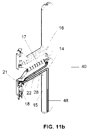
Foaming or frothing takes place in the frothing device 40, as it will be
further
explained which is configured to constitute a closed fluid (milk) system using
Venturi
technology. Looking in more detail at Figure 11 b, the fluid (typically milk)
is sucked from
the fluid container 30 through a fluid conduit 28 by Venturi effect through
injection of steam
by a steam conduit 21. Air is also added in a controlled manner through an air
conduit 22
controlled by a solenoid valve 36 (comprising also electronics) arranged in
the cover 31 of
the machine 100.
By acting on the valve 36, it is possible to add air to the fluid in order to
foam it,
adding more or less quantity of air depending on the foaming characteristics
targeted, or
not adding any air at all. Once steam is not injected any more, the remaining
fluid in the
frothing device 40 flows back to the fluid container 30. The air conduit 22 is
connected to
the valve 36 and to a controlled air hole having a diameter typically of 0.2
mm. The
dimension of this air hole is such that optimised fluid foam is obtained. For
milk foam, the
air conduit 22 is connected to the air hole; for hot milk, the valve 36 is
closed, so the air
supply is cut to the frothing device 40. By controlling this air hole to 0.2
mm, the quantity of
air injected is controlled so that proper foaming is achieved.
Moreover, the air conduit 22 in the frothing device 40 of the invention has a
certain
length so that eventual milk remaining in it and rising towards the machine
will never be
able to reach the machine, so that no contamination of fixed parts of the
machine can
possibly occur: eventual remaining of milk will always stay in the frothing
device 40, that
can be unfolded for being easily cleaned, so hygiene is always maintained.
The frothing device 40 of the invention is therefore configured to work in
such a way
that, once it is closed and arranged in the machine 100 (further explanation
on this will
follow), steam is injected into the steam conduit 21: by Venturi effect, milk
is sucked
through the fluid conduit 28. The air conduit 22 is adding a controlled amount
of air to the
fluid (milk) to be foamed thanks to it being controlled by the valve 36
arranged in the
machine cover. Foaming takes place in the expansion chamber 18 by rapid
expansion and
by the hot water vapour, as it can be seen in Figures 11 b and 12b. When the
valve 36 is
closed, no air is added through the air conduit 22 so only hot milk (not
foamed) is
dispensed. Once steam is cut, remaining milk flows back to the container 30.
CA 02995652 2018-02-14
WO 2017/050933
PCT/EP2016/072603
9
Figures 11 ab and 12ab show in detail the configuration of the frothing device
40 of
the present invention, according to two possible embodiments. Preferably, the
frothing
device 40 is made reusable and foldable, the fact of being made foldable
allowing very
easy cleaning. The frothing device 40 is typically made of two parts, a first
body 15 and a
second body 16, typically a first half 15 and a second half 16, typically
joined by means of
a joining element 17 preferably a hinge such that when put together, form the
complete
frothing device 40. The frothing device 40 further comprises a sealing part
14, typically
made in rubber or silicon, helping the proper joining of the two halves 15,
16. The sealing
part 14 can be over moulded onto one of the two halves 15, 16 or it can be
inserted
separately. In operational mode, the two halves 15, 16 are folded together and
maintained
joined thanks to the sealing part 14, creating a closed milk fluid system
using Venturi
technology. Once unfolded, which can be easily done thanks to the hinge
element 17, the
device 40 can be easily cleaned as it is made accessible by being deployed (it
can be
cleaned by using water, directly from the tap, for example, or even in the
dishwasher).
Each of the halves 15, 16 comprises cavities at its surface such that when the
halves are
brought together, the cavities configure the air conduit 22, the fluid conduit
28 and the
expansion chamber 18.
Preferably, the joining element 17 will be configured as a hinge: however,
other
embodiments are also possible, such as clamps or other means allowing rapid
and easy
opening and closing of the two bodies of the frothing device 40.
A different embodiment of the frothing device 40 of the invention is shown in
Figures
12ab, now comprising a separate aspiration tube or pipe 48 that is connected
to the fluid
conduit 28 that is made smaller in this embodiment, as seen in Figure 12b. The
aspiration
tube 48 is connected to the fluid container 30 and sucks the fluid by the
Venturi effect
when steam is injected in the steam conduit 21. Aspiration of milk is done
through the tube
48 and milk is then canalized through the rest of the fluid conduit 28 toward
the expansion
chamber 18. This embodiment allows that the tolerances in the configuration of
the
cavities in the frothing device 40 are less tight or strict, so it is easily
configured. Typically,
the pipe 48 is made flexible, preferably made of silicone.
CA 02995652 2018-02-14
WO 2017/050933
PCT/EP2016/072603
As represented in Figure 12b, the expansion chamber 18 is made essentially
cylindrically, comprising a first section that is then strongly reduced and
then again greatly
expanded so that frothing can occur through these abrupt changes in section.
5
When the frothing device 40 is arranged in the machine 100, it is tightly held
in place
(i.e. the two halves 15, 16 are tightly maintained together so that a closed
milk fluid system
using Venturi technology is created) by means of a metallic cooling block 81
(also
refrigerating the frothing device 40) and further by a foaming receiver 90.
The fact that the
block 81 is further cooled is important as it maintains the milk inside and
the possible milk
10
remaining inside the device refrigerated, which eliminates all kind of
hygienic problems.
The metallic cooling block 81 assures tightness and permanent refrigeration of
the frothing
device 40.
Further embodiments or configurations for the machine 100 are also possible,
comprising for example as shown in Figure 6 two frothing devices 40: the
machine 100 will
be provided with two foaming receivers 90, one for each frothing device.
Figures 7abc
show another possible execution where three frothing devices 40 are provided
in the
machine 100, which therefore comprises three foaming receivers 90. The machine
can
comprise several foaming receivers 90 that can receive one or several frothing
devices 40,
that can be simultaneously used or not. Figures 8abc show for example a
configuration
where the machine comprises three foaming receivers 90 though only one
frothing device
40. Similarly, Figures 9abc show a machine having three foaming receivers 90
and two
foaming devices 40.
Preferably, the foaming receiver 90 further comprises a frothing cover 500 at
the end
part of the receiver and connected to the outlet of the frothing device 40:
the purpose of
this cover 500 is to avoid splashes on the machine when frothing or foaming
takes place.
Typically, the shape of this frothing cover 500 is circular but any other
shape can be used
that is designed to be big enough to avoid splashing.
Figures 4a and 4b show a frontal and a cut view of the machine 100: Figure 4b
shows the first cooling unit 10 intended to refrigerate the primary
refrigerated container for
the fluid (milk), and the second cooling unit 20 intended to refrigerate the
secondary
CA 02995652 2018-02-14
WO 2017/050933
PCT/EP2016/072603
11
refrigerated compartment 8 where the frothing device 40 is arranged. The fluid
container
30 is also shown in Figure 4b where the fluid inside its volume is cooled by
the cooling
walls 62 and also by the cooling block 61 arranged within its cavity 33. As
represented in
Figure 4b, the frothing device 40 is in fact refrigerated by means of a
metallic cooling block
81 arranged around the frothing device and refrigerated by the second cooling
unit 20.
This metallic cooling block 81 is also holding the frothing device 40 in
place, assuring
tightness and its permanent refrigeration. The frothing device 40 is shown
having a
connection to a steam conduit 21 and to an air conduit 22, through which steam
and air
are respectively injected.
In the machine, steam is generated by conventional known means: a watertank
26, a
waterpump 27 and a thermoblock 38 connected to the steam conduit 21. A
security valve
24 is also provided in the machine 100 acting on the opening and closing of
the steam
conduit 21. Similarly, as already disclosed, the air conduit 22 is connected
to a solenoid
valve 36 which controls the air injected in the frothing device 40: when only
hot milk is
desired (that is, no milk foam is targeted), the air entry is cut and only
fluid goes through
the frothing device, the fluid being then heated by means of the steam
injected through the
steam conduit 21.
According to different possible embodiments of the invention, it is also
possible that
the fluid can be heated by other means different from steam, for example using
conduction, radiation (using infrared or halogen lamps, for example), hot air,
induction, etc.
The machine allows simplified handling and cleaning of the parts involved in
the fluid
preparation (typically milk): this is possible thanks to these parts being
continuously
refrigerated; therefore, complex cleaning and rinsing cycles are avoided.
Ideally, the machine 100 comprises two cooling units, one for cooling the
fluid tank
(first cooling unit 10), and another one for cooling the foaming device
(second cooling unit
20).
As an alternative and less expensive solution, the machine 100 can be
configured
such that it comprises no cooling unit (so the machine is made in fact with a
reduced size)
CA 02995652 2018-02-14
WO 2017/050933
PCT/EP2016/072603
12
and the fluid container and the frothing device are refrigerated externally,
in a refrigerator
or outside unit: after each milk and/or foam preparation, the fluid container
and the
foaming device are introduced in an external refrigerator for cooling. Still,
the same easy
cleaning is possible as the removal of the fluid container and the deployment
of the
frothing device remain unchanged.
Another variant of the present invention is shown in Figures 5a, 5b and 5c
attached.
According to this variant, there is only one cooling unit 10 arranged in the
low part of the
housing 1 of the machine. This cooling unit actually cools a block 300
comprising an inner
volume 302 where the container 30 with the fluid will be arranged and a wing
part 303,
also refrigerated, comprising an insert part 301 to receive the outlet nozzle
60 of the
frothing device 40. Similar insert part 301 is shown in the embodiment of
Figure 2b, also
intended to receive the outlet nozzle 60 of the frothing device 40. Therefore,
with this
embodiment, only one cooling unit 10 is able to cool from below both the fluid
in the
container 30 and the frothing device 40 in its outlet. In a similar way, a
cooling block 61 is
also arranged in the inner volume 302 cooperating with the corresponding
cavity 33 in the
container 30. The top opening 2 of the machine, as represented in Figures 7a
and 7c,
comprises the steam entry 70 and the air entry 80 that are automatically
connected to
corresponding matching entries in the frothing device 40. As it is clear, the
top opening 2
does not comprise now any metallic block 81, which also presents the advantage
of
making this top opening 2 much lighter. This embodiment comprises now only one
compartment, inner volume 302, corresponding to the primary compartment 6 in
the
previous embodiment, where the fluid container 30 is arranged.
According to the invention, the air and steam entries are provided directly
through
the top opening 2 so direct automatic connection to the frothing device 40 is
made by
simply closing the top opening 2 of the machine. However, it is also possible
and should
be comprised within the scope of the present invention, that there are
connections done
manually by the user from the steam and air entries 70, 80 to the frothing
device 40.
It is also important according to the invention that the frothing device is
tightened
when arranged at the foaming receiver 90, as shown in Figures 3c and 3e, for
example.
Tightness is indeed necessary for being able to suck fluid by Venturi effect
from the fluid
CA 02995652 2018-02-14
WO 2017/050933
PCT/EP2016/072603
13
container 30 and let it pass through the outlet nozzle 60. Preferably, for
obtaining this
tightness, the foaming receiver 90 has a shape complementary to that of the
frothing
device 40.
Although the present invention has been described with reference to preferred
embodiments thereof, many modifications and alternations may be made by a
person
having ordinary skill in the art without departing from the scope of this
invention which is
defined by the appended claims.