Note: Descriptions are shown in the official language in which they were submitted.
Insert for use in an injection molding nozzle and injection molding nozzle
with such an
insert
The invention according to the preamble of claim 1 relates to an insert for
use in an injection
molding nozzle as well as an injection molding nozzle for an injection mold
with an insert
according to the invention according to claim 10.
Injection molding nozzles, especially hot-channel nozzles, are used in
injection molds in order to
supply a flowable compound, such as a plastic material, at a given temperature
under high
pressure to a releasable mold insert. They usually have a material tube with a
flow channel which
is fluidically connected by an inlet opening to a distributor channel and
emerges by an outlet
opening in the gate opening of the mold insert (mold cavity).
All of the following remarks apply to both hot-channel systems and cold-
channel systems.
So that the flowable material within the flow channel of the hot-channel
nozzle does not cool
down prematurely and harden, a heating device is provided, being placed or
arranged on the
outside of the material tube. Moreover, in order to ensure that the flowable
compound is held at a
uniform temperature up to the gate opening, a heat conducting sleeve made of a
high thermal
conductivity material is inserted at the end side in the material tube, being
a continuation of the
flow channel and forming at the end side the outlet opening for the injection
molding nozzle.
In the case of an open nozzle, the heat conducting sleeve is usually designed
as a nozzle
mouthpiece and provided with a nozzle tip, terminating by its conical tip in
or shortly before the
plane of the gate opening. In the case of a needle valve nozzle, a tight seat
for a valve needle is
formed at the end side in the outlet opening of the heat conducting sleeve,
which can move back
and forth by means of a needle drive between an open and a closed position.
When processing abrasive materials or injection molding compounds which
contain abrasive
components, severe wear may occur on the heat conducting sleeve, especially at
the outlet
CA 2996606 2018-02-26
- 2 -
opening, so that the heat conducting sleeve or ¨ depending on the design ¨ the
entire hot-channel
nozzle needs to be replaced rather often. Especially in the case of needle
valve nozzles, damage
occurs to the tight seat for the valve needle, so that this can no longer be
moved precisely from
an open to a closed position during the periodic movement and the outlet
opening is no longer
tightly closed.
Furthermore, the individual components of an injection molding nozzle are
generally exposed to
an abrasive and adhesive wear. This wear is due to the fact that metallic
components rub against
other metallic components, without it being possible to use a lubricant, which
might contaminate
the injection molded products being produced.
In order to prevent wear, WO 2005/018906 Al proposes an insert which is
preferably made from
a wear-resistant material. This is arranged at the mold insert-side end of a
nozzle mouthpiece and
is designed to be lengthwise movable either in itself or together with the
nozzle mouthpiece.
During the operation of the injection molding nozzle, the insert is clamped
between the nozzle
body and the mold insert. The insert serves for protection of the nozzle
mouthpiece against
heavy wear and optimizes the needle guidance of needle valve nozzles, since it
functions as a
centering body for both the valve needle and for the nozzle.
The drawback here is that the insert can only be made from a unitary material.
Therefore, the
insert either consists of a wear-resistant material or one uses high thermal
conductivity material ¨
as in another embodiment of WO 2005/018906 Al.
WO 2003/070446 Al also proposes an insert which functions as a needle valve
guide and as a
wear protection means. Besides the embodiment already known from WO
2005/018906 Al with
a single-piece insert made either from thermally insulating or thermally
conducting material, WO
2003/070446 Al proposes a two-piece embodiment of the insert, in which the two
individual
parts of the insert may have different material properties. For example, an
outer part (insulating
part) made from a thermally insulating material and an inner part (guide part)
of a thermally
conductive material or a wear-resistant material is proposed. The thermally
insulating material is
used to reduce heat losses to the mold insert and the thermally conductive
material is used to
conduct heat from the tip to the melt in the guide opening.
CA 2996606 2018-02-26
- 3 -
The drawback to this embodiment is that the individual parts of the insert
need to be made
separately of the different materials and to be mounted individually in the
injection molding
nozzle. Both parts also need to be removed separately when a replacement
becomes necessary.
This increases the labor cost and the installation costs. Moreover, it may
happen that the two
single parts wear down at different rates, which is impractical for the
handling and causes
additional expense in the maintaining and inspecting of the injection mold. A
further drawback is
that the two-piece or multi-piece inserts have relatively large dimensions,
which has unfavorable
impact on the size of the hot-channel nozzle and thus on the possible hole
gauges or cavity
spacings.
The goal of the invention is to overcome these and other drawbacks of the
prior art and to create
a compact insert for an injection molding nozzle, making use of several
material properties in a
single component part. In particular, a heat dissipation to the injection mold
or the mold insert
should be prevented. Furthermore, it should make possible a small design size
of the injection
molding nozzle. In particular, it should have an economical design with small
dimensions and
simple means and it should be easy to handle inside the mold. Moreover, the
insert should be
robust to the high alternating stress of cooldown and heating, and be
resistant to wear.
Furthermore, the insert should be interchangeable.
The main features of the invention are indicated in the characterizing
passages of claim 1 and
claim 10. Embodiments are the subject matter of claims 2 to 9 and 11 to 15.
In an insert for use in an injection molding nozzle, with an insert body made
from at least one
high thermal conductivity material, in which at least one flow channel is
formed with an inlet
opening and an outlet opening, wherein the insert body comprises a neck
section, for joining to
the injection molding nozzle, an end section, for inserting into a mold cavity
of a mold insert,
and a flange with a stopping surface projecting radially with respect to the
end section, wherein
the stopping surface is formed on a surface of the radially projecting flange
facing the outlet
opening, the invention proposes that the stopping surface and the end section
have at least partly
an outer coating made of a second material with a low thermal conductivity.
CA 2996606 2018-02-26
- 4 -
It is thus possible, in only a single component, which is inserted for example
into the lower,
mold insert-side end of a material tube or a heat conducting sleeve of the
injection molding
nozzle, to combine several material properties and to use it for the injection
molding nozzle and
the flowable material being processed, without several different components
being required and
having to be mounted. The different materials can be chosen and combined
according to the
requirements, in particular the second material of the coating having a lower
specific thermal
conductivity than the first material. It is preferable to make the insert body
of the insert from a
high thermal conductivity material, in order to bring the heat generated by a
heating of the
injection molding nozzle as far as possible up to the gate opening. The
coating, on the other
hand, is made from a material with low thermal conductivity, in order to
lessen the heat
transmission to other components. The coating is preferably placed by force
locking, integral
bonding, and/or form fitting on the radially outer surface of the end section
and the stopping
surface of the insert body. This ensures a durable connection of the coating
and the insert body to
each other. The end section and the stopping surface made from a high thermal
conductivity
material and the coating made from a second material are preferably joined
together across a
contact surface.
In one preferred embodiment, it is proposed that the end section and the
stopping surface have
substantially entirely a coating of a second material. Thanks to the
insulating properties of the
coating, a heat transfer from the insert body to the surrounding components of
the nozzle or the
mold is prevented as much as possible, without changing the structural size of
the insert body.
Preferably it is provided that both the high thermal conductivity material and
the second material
with a low thermal conductivity are wear-resistant and thus withstand
mechanical stresses due to
the flowable compound or surrounding components, for example in the form of a
mold insert.
Thanks to the coating of the end section and the stopping surface with a
second different
material, the advantageous properties of the materials can be used precisely
and in the smallest
structural space, as best as possible. A cost and maintenance intensive
installation of two
individual parts is avoided. Likewise, no costly sealing elements or sealing
surfaces are needed
between the two materials, which might result in leakage at or in the
injection molding nozzle or
CA 2996606 2018-02-26
- 5 -
in the mold. Instead, the coating and the insert body are constantly joined
together firmly and the
insert forms a unitary component with minimal dimensions in its handling.
In one preferred embodiment, the second material with a low thermal
conductivity is a ceramic
material. Ceramic materials have a low thermal conductivity and furthermore
they are wear-
resistant and durable. An insert can therefore be provided which transfers
little or no heat to the
mold insert and furthermore has good resistance to mechanical stresses.
Preferably, the second
material with a low thermal conductivity comprises zirconium oxide.
Ceramics based on zirconium oxide have a low thermal conductivity, which is
lower than the
thermal conductivity of metallic materials, such as steel, which are
preferably used as high
thermal conductivity material of the insert body. In addition, zirconium oxide
ceramics have
expansion coefficients similar to metallic materials, especially steel. Thus,
it is ensured that the
outer coating also withstands rapid heating and cooling processes.
Alternatively, it is preferably proposed that second material with a low
thermal conductivity
comprises a plastic. Plastics have a low thermal conductivity and are
furthermore easy to work,
so that the manufacturing of an insert with a plastic coating is simple and
economical.
Preferably, the plastic contains polytetrafluorethylene. This plastic has a
high melting
temperature and long-term service temperature, so that the coating does not
melt during use and
the insert according to the invention has the longest possible service life.
Preferably, the high thermal conductivity material of the insert body and the
second material
with low thermal conductivity of the coating have substantially the same
coefficient of thermal
expansion. With almost the same coefficients of expansion, the insert can go
through many
heating and cooling cycles without the coating peeling off, for example.
In one preferred embodiment, the end section has an end face, in which the
outlet opening is
recessed, the outer coating of the second material with a low thermal
conductivity ending before
the end face. In this way, the end face of the insert consists exclusively of
the high thermal
conductivity material of the insert body, for example, which preferably
comprises a metallic
material. The end face of the insert is subjected to an increased mechanical
loading, since it is
continually placed in contact with a gate opening of a mold insert.
Furthermore, the end face is
CA 2996606 2018-02-26
- 6 -
also exposed to increased mechanical loads when mounting the insert in an
injection molding
nozzle. These increased mechanical loads might result in faster wearing of the
less wear-resistant
material and a peeling of the coating at an interface between two materials.
The avoidance of
such an interface ensures a long-lasting use of the insert.
Preferably, the outer coating of the end section and/or the stopping surface
is arranged in a recess
of the end section and/or the stopping surface, so that the end section and/or
the stopping surface
of the high thermal conductivity material and the outer coating of a second
material form a flat
outer surface at a boundary surface between the two materials. Thanks to this
design, no
projecting edge is created, which would be subjected to increased mechanical
loads and would
result in intensified wearing of the projecting material, especially the
coating. The outer surface
of the insert body is the radially outer surface of the insert body in this
case. The outer surface of
the flange, facing the outlet opening of the end section, corresponds to the
stopping surface. This
design of the insert results in a form fitting connection of the end section
and the stopping
surface of the flange with the outer coating.
In an alternative embodiment it is proposed that the coating fully covers the
end face of the end
section, the outlet opening being formed in the coating. Also with this
embodiment, the end face
exposed to an increased mechanical loading has no interface between two
different materials, so
that a peeling of the coating material is prevented. In this way, a long-
lasting use of the insert is
assured.
Furthermore, the coating of a material with a low thermal conductivity which
also covers the end
face of the insert body has the effect that the insert body is thermally
insulated against a mold
insert in the best possible way. The heat from a heating is not transferred to
the mold insert, so
that the insert of the injection molding nozzle has less heat loss and energy
costs can be
economized.
The coating of a second material with a low thermal conductivity can be
applied with known
coating methods to the end section and the stopping surface, especially in the
region of the
recess.
CA 2996606 2018-02-26
- 7 -
In one preferred embodiment, it is proposed that the flange has a thread on a
radially outer
surface. By means of this thread, the insert can be easily mounted in and
removed from the
injection molding nozzle. For example, if the insert is worn down or parts of
the insert, such as
the coating, become damaged, the insert can be simply replaced, without costly
repair work
being needed for the injection mold.
Preferably, the insert body is rotationally symmetrical to a longitudinal axis
L. In this way, not
only can the insert be produced easily, but also it can be installed quickly
and without error in the
injection molding nozzle.
In one preferred embodiment, the insert body of high thermal conductivity
material with the end
section, the neck section and the flange is designed as a single piece. A
single-piece insert body
can be produced easily and economically and furthermore it assures a durable
functioning of the
insert, especially the flow channel. The entire insert body comprises a single
high thermal
conductivity material.
In an alternative embodiment it is preferably provided that the insert body is
two-piece or two-
part. Preferably the insert body comprises a first part and a second part,
wherein the first part is
formed substantially by the neck section and the second part substantially by
the end section. It is
preferably provided that the first part is made from a high thermal
conductivity material and
extends from the neck section of the insert body as far as a boundary surface
and the second part
is made from a third material, which is different from the high thermal
conductivity material of
the first part, wherein the second part extends from the boundary surface as
far as the end section
of the insert body, and wherein the first part and the second part are joined
firmly to each other
in and/or along the boundary surface. The second part comprises at least
partially the coating of a
second material with a low thermal conductivity, in particular the second part
comprises the
coating of the second material in the region of the end section and the
stopping surface.
In this way, it is possible to combine several material properties in only a
single component,
which is inserted for example into the lower, mold cavity-side end of a
material tube or a heat
conducting sleeve of the injection molding nozzle, and to use the flowable
material being worked
without requiring and having to install several different components. The
different material
CA 2996606 2018-02-26
- 8 -
properties can be chosen and combined in accordance with the requirements. If
the first part of
the insert is made from a high thermal conductivity material, the heat
generated by a heating of
the injection molding nozzle can be taken as far as possible up to the gate
opening. The second
part, on the other hand, made from a third material, can be produced for
example from a wear-
resistant material, in order to reduce the wear on the insert and thus
increase the service life of
the injection molding nozzle, especially when the second part of the insert
forms the tight seat
for a valve needle.
The first part and the second part of the insert can advantageously be made as
separate parts,
which are precisely and firmly joined together after their fabrication.
Alternatively, it is also pos-
sible to produce at first a rough blank from a composite of the high thermal
conductivity material
and the third material and then fabricate the insert from this composite.
Thanks to the connection
of the two parts of the insert consisting of two different materials with an
additional coating, the
advantageous properties of the materials can be chosen precisely and in the
smallest structural
space, as best as possible. A cost and maintenance intensive installation of
different single parts
is avoided. Likewise, no costly sealing elements or sealing services are
needed between the two
parts, which might result in leakage at or in the injection molding nozzle or
in the mold. Instead,
the two parts are constantly joined together firmly and the insert forms a
unitary component with
minimal dimensions in its handling.
The connection extends by virtue of the boundary surface between the different
materials used,
so that although the properties of several materials are combined in a single
component, at the
same time a clear demarcation of materials is ensured on the different parts.
A mixing of the two
substances outside the boundary surface is prevented. This contributes to the
optimal and precise
utilization of the materials when using an insert in an injection molding
nozzle.
Embodiments of the invention propose that the first part and the second part
are joined together
by integral bonding, form fitting, or frictional locking. With an integrally
bonded connection,
minimum dimensions can be achieved. But mechanical connections in the form of
a form fitting
or a frictional locking are also conceivable, for example by interlocking,
screw fastening, press
fitting or shrink fitting.
CA 2996606 2018-02-26
- 9 -
Due to the limited structural space, it is especially advantageous when the
first and second part
are joined together with integral bonding by means of welding, preferably by
means of diffusion
welding or laser welding.
Welding has proven to be the optimal method for connecting the first and the
second part, be-
cause the first and the second part are usually formed from a metallic
material and welding can
produce a reliable and long-lasting stable connection between the parts.
Diffusion welding in
particular has benefits over other welding methods. The quality of the welded
connections is
exceptionally high. A pore-free, tight material composite is formed, meeting
the highest me-
chanical, thermal and corrosion requirements. With diffusion welding, it is
not necessary to use
any added material, so that the seam has no foreign alloy components and thus
possesses proper-
ties similar to those of the base materials, when properly designed.
Furthermore, thanks to no
molten fluid phase in the joining process, a highly precise and contour-true
welding can be as-
sured.
Besides welding, methods such as soldering or gluing may also be considered
for the forming of
integrally bonded connections.
Alternatively, the first part can be joined to the second part by means of a
mechanical connection
arrangement. For this purpose, a locking connection, a screw connection, a
press fitting or a bay-
onet connection can be used, among others. The two parts can also be joined
together by shrink
fit. All of the aforementioned types of connection have the benefit that such
a connection of the
first part to the second part is durably firm and tight.
It is especially advantageous when the third material of the second part is a
wear-resistant mate-
rial. In this way, it is possible to reduce the wear on the insert ¨ for
example in the region of a
needle guide ¨ on account of the repeated sliding of the valve needle along
the inner walls of the
flow channel during active operation of the injection molding nozzle. At the
same time, a high
thermal conductivity design of the first part of the insert, which can be
arranged for example on a
heat conducting sleeve, ensures an optimal temperature distribution in the
gate region.
CA 2996606 2018-02-26
- 10 -
It has proven to be advantageous when the thermally conductive material and
the wear resistant
material have a high thermal expansion. Thanks to the use of a material with
high thermal expan-
sion, the insert expands specifically during the heating of the injection
mold, so that after reach-
ing the operating temperature of the injection molding nozzle the insert is
optimally clamped
between material tube and/or heat conducting sleeve on the one hand and mold
insert on the oth-
er hand and forms a durably tight arrangement.
In another advantageous design, the material of the first part and the
material of the second part
have an identical or nearly identical coefficient of expansion.
If the coefficients of expansion of the two parts of the insert are different,
the difference between
the coefficients of thermal expansion of the thermally conductive and the wear-
resistant material
takes into account the elastic capacities of the connection between the first
and the second part,
so that the two parts of the insert are always joined together durably and
firmly.
In a special embodiment, the wear-resistant material is a tool steel. This is
distinguished by good
wear protection properties. Tool steel is more economical than other materials
with comparable
wear protection properties. In particular, a tool steel with low thermal
conductivity may be ad-
vantageous, because in this case there is a thermal separation of the plastic
melt from the mold
insert of the injection mold, which prevents a premature cooldown of the
plastic melt in the re-
gion of the second section. The additional coating of a material with a low
thermal conductivity
additionally supports this effect.
Alternatively, a ceramic which is distinguished by high wear resistance and
low thermal conduc-
tivity could also be used as the wear-resistant material.
A further embodiment of the invention proposes that the boundary surface along
which the first
part is connected to the second part extends perpendicular to or obliquely to
the longitudinal axis
of the insert body. This produces, for example, a disk-shaped boundary surface
with minimal
expansion. Thanks to the perpendicular run of the boundary surface, an optimal
connection can
be produced between the first and the second part.
CA 2996606 2018-02-26
- 11 -
Alternatively to this, the boundary surface may also extend obliquely to the
longitudinal axis of
the insert body, for example, when a larger boundary surface is desired. The
latter may be coni-
cally formed, for example. Thanks to a boundary surface oriented obliquely to
the longitudinal
axis, an integrally bonded connection can be strengthened in particular, since
in this case a larger
section is available as boundary surface.
In another special embodiment, the flange is preferably formed by the first
part or the second
part. In either variant, the flange is formed uniformly from one material and
exhibits the proper-
ties of the respective material. In this way, the flange may either continue
the heat conducting
function of the neck section, for example, or enlarge the region of the end
section which is pro-
tected by the wear-resistant material.
According to another embodiment, the flange is formed by the first part and
the second part. In
this way, the properties of the two materials can be combined optimally in the
narrowest space.
Since the flange functions primarily as a supporting flange, it comprises both
regions having
contact with the mold insert and regions which may lie against the material
tube, the nozzle
mouthpiece and/or the heat conducting sleeve, as required. Different
requirements must be ful-
filled in the two regions of the flange. While the temperature in the
transitional region between
flange and first section is constantly maintained high, at the same time the
heat transfer from the
material tube, the nozzle mouthpiece or the heat conducting sleeve to the mold
insert is minimal.
Furthermore, a more intense wearing must be assumed precisely at the contact
surfaces, so that
in these places a stronger wear protection is assured. Since the two parts of
different materials
form the flange, these opposite requirements can be fulfilled in a single
component in the small-
est space. This also holds in particular for the overall insert.
According to another advantageous embodiment, the insert forms a centering
body for a valve
needle of an injection molding nozzle. In this case, the insert forms in the
first part and/or in the
neck section a flow channel wall which tapers conically in the direction of
the flange. Such a
wall centers the valve needle during the closing movement, so that the free
end of the valve nee-
dle can always run precisely in its tight seat. Preferably, the trend of the
flow channel in the re-
gion of the first part and/or neck section is such that the valve needle is
oriented already to the
gate opening of the insert. Thus further prevents an excessive wear on the
valve needle.
CA 2996606 2018-02-26
- 12 -
According to another important embodiment, the second part forms a tight seat
for a valve nee-
dle of an injection molding nozzle. This can be accomplished, for example, by
adapting the di-
ameter of the flow channel in the region of the end section to the
circumference of the valve nee-
dle of a needle valve nozzle. Corresponding embodiments have the advantage
that the wear on
the insert in the region of the end section, caused by repeated sliding of the
valve needle along
the surfaces of the flow channel, is significantly reduced.
According to another embodiment, the second part of the insert is configured
to form, with its
front end, a section of a wall of a mold cavity.
The neck section of the insert body is designed such that the insert can be
optimally adapted by
its neck section to the material tube, the nozzle mouthpiece or the heat
conducting sleeve of an
injection molding nozzle and thus can be easily inserted into these parts or
placed on these parts
¨ e.g., in the form of a sleeve. The end section, on the other hand, can be
optimally adapted to
another component, preferably to the mold insert or a mold nest plate ¨ so
that a problem-free
installation in an injection mold is assured. The flange may function as a
supporting flange,
wherein the stopping surface of the flange rests against a mold insert and the
top side of the
flange rests against the material tube, the nozzle mouthpiece or the heat
conducting sleeve. On
the whole, such a geometry produces a component whose dimensions can be
optimally adapted,
with minimal design size, to the geometry of the injection molding nozzle and
the mold insert or
the casting being produced. In the latter case, the insert acts to dictate the
shape of the article
being cast.
In one preferred embodiment, it is proposed that the end section with the
outer coating is
designed to form at least one sealing surface with a mold insert along an
outer circumference.
Thanks to the most precise possible adapting of the end section of the insert
to the mold cavity of
a mold insert, injection molded articles can be produced as precisely as
possible. Furthermore,
thanks to the coating according to the invention, a heat transfer from the
insert to the mold insert
is significantly reduced, so that a cooldown of the melt in the injection
molding nozzle is
prevented or at least minimized. Furthermore, this embodiment has a positive
impact on the
CA 2996606 2018-02-26
- 13 -
holding times during the molding process, which may be limited especially in
the case of needle
valve systems and thus involve risk.
Furthermore, the invention relates to an injection molding nozzle for an
injection mold with an
insert according to the invention. The injection molding nozzle may be either
a hot-channel
nozzle or a cold-channel nozzle. The insert may find use both in injection
molding nozzles with
open gate and nozzle tips and in injection molding nozzles with heat
conducting sleeve and
needle valve closure.
Injection molding nozzles with the insert according to the invention will
profit from the coating
of the insert body, i.e., only a single component needs to be handled during
the installation.
Thanks to the combination of several different materials, the advantageous
properties of the
materials can be utilized precisely and in the smallest design space, in the
best possible way.
Thanks to the use of a high thermal conductivity material for the insert body
or at least for the
first part of the insert body and the providing of a coating of the end
section and the stopping
surface by a material with a low thermal conductivity, an optimal temperature
distribution and
thermal separation is achieved when feeding the melt inside the nozzle tip to
the mold insert.
Since a firm connection exists between the insert body and the coating, which
can withstand
even high alternating loads due to heating and cooling of the mold, not only
does this avoid
complicated and costly handling due to the installing of several individual
parts, but also it
provides a long-lasting and thus inexpensive injection molding nozzle.
When the injection molding nozzle is a needle valve nozzle, this has the
further advantage that
the insert additionally functions as a centering body, because the needle is
guided precisely and
with stable position inside the insert. This avoids damage to the valve
needle, as well as wear
effects on the insert.
The injection molding nozzle itself may comprise different components in
different
embodiments. All embodiments of the injection molding nozzle comprise a
material tube, in
which at least one flow channel is formed, which is fluidically connected to a
mold cavity of the
injection mold formed by at least one mold insert.
CA 2996606 2018-02-26
- 14 -
Depending on the embodiment, the injection molding nozzle furthermore has a
heat conducting
sleeve, which can be designed as a nozzle mouthpiece. The heat conducting
sleeve is inserted
into the material tube at the end, or mounted on the material tube, and it
forms the outlet opening
for the flow channel. The heat conducting sleeve is made from a high thermal
conductivity
material so that the melt can be fed at constant high temperature to the mold
insert, without
forming a so-called cold plug.
The insert according to the invention can be arranged at the mold insert-side
end of the material
tube, wherein the insert can be arranged at the mold insert side directly in
or on the material tube
or in or on a separate heat conducting sleeve. The insert may be inserted into
or onto the material
tube or the heat conducting sleeve. The neck section of the insert body is
adapted accordingly for
this. The insert is furthermore formed separate from the other components of
the injection
molding nozzle and constitutes a separate component of the injection molding
nozzle. In this
way, the materials of the insert can be chosen independently of the materials
of the other
components of the injection molding nozzle and be individually adapted to the
particular
requirements.
It has proven to be especially advantageous for the insert to be designed
lengthwise movable in
relation to the material tube, the nozzle mouthpiece or the heat conducting
sleeve and the mold
insert and during the operation of the injection molding nozzle ¨ i.e., as
soon as the mold has
reached its operating temperature - it is clamped between the material tube
and the mold insert,
the nozzle mouthpiece and the mold insert or between the heat conducting
sleeve and the mold
insert. Thus, with this design, no length change due to different coefficient
of thermal expansion
on the hot-channel and/or cold-channel system needs to be taken into account.
Thanks to the
lengthwise movable seat, it is possible to install and remove the insert
quickly and conveniently.
No tools or other accessories are needed for this. Neither are any additional
parts or accessories
provided for the fastening of the insert in the injection molding nozzle, such
as screw threads,
threaded sleeves, or the like, either on the insert itself or in the injection
molding nozzle, because
the insert is reliably secured by clamping during the operation of the
injection molding nozzle.
Even so, the insert can always be quickly and economically replaced.
CA 2996606 2018-02-26
- 15 -
Furthermore, it is advantageous when the neck section is form fitted at least
for a portion to the
material tube, the nozzle mouthpiece or the heat conducting sleeve and the end
section with the
coating is form fitted at least for a portion to the mold insert. Thanks to
the form fitting, a
constantly tight connection is achieved, thereby preventing the melt from
getting into interstices,
while a lengthwise movement of the insert constantly remains possible, in
order to balance out
any heat-related changes in position of the injection molding nozzle. Thus,
the insert with the
other parts of the injection molding nozzle forms a plug-in system, from which
the insert can be
easily removed by pulling out without the use of tools, yet at the same time
the injection molding
nozzle is reliably secured by clamping during its operation.
Further features, details and benefits of the invention will emerge from the
wording of the claims
as well as the following description of sample embodiments with the aid of
drawings. There are
shown:
Fig. 1 a schematic longitudinal section through a first embodiment of an
insert according to the
invention,
Fig. 2 a schematic longitudinal section through another embodiment of an
insert according to
the invention,
Fig. 3 another schematic view of an embodiment of an insert according to the
invention,
Fig. 4 a schematic longitudinal section through another embodiment of an
insert according to
the invention,
Fig. 5 a schematic longitudinal section through another embodiment of an
insert according to
the invention with a two-piece insert body and
Fig. 6 a schematic longitudinal section through another embodiment of an
insert according to
the invention with a two-piece insert body.
When working with thermosetting plastics and elastomers, where the plastic
hardens under tem-
perature influence, cold-channel systems are used accordingly in place of hot-
channel systems.
Therefore, when hot-channel systems are described in the following, cold-
channel systems are
also always meant accordingly, depending on the application.
CA 2996606 2018-02-26
- 16 -
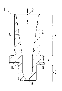
Fig. 1 and 2 show a longitudinal section through an insert 1 according to the
invention for an
injection molding nozzle (not shown). The insert 1 is formed by a
corresponding insert body 2
made from a high thermal conductivity material. Here, the insert body 2
comprises a neck sec-
tion 3, a flange 4 and an end section 5. The insert body 2 can be joined by
its neck section 3 to an
injection molding nozzle, for example by inserting it into or placing it on
the injection molding
nozzle. The flange 4 projects radially with respect to the neck section 3 and
the end section 5.
The end section 5 can be inserted into a mold cavity of a mold insert (not
shown) and is prefera-
bly adapted to the shape of the mold cavity. Furthermore, the insert body 2
has at least one flow
channel 6 with an inlet opening 7 and an outlet opening 8. The end section 5
and a stopping sur-
face 9 of the flange 4 have an outer coating 10 made from a second material
with a low thermal
conductivity, the stopping surface 9 being the surface of the flange 4 facing
the outlet opening 8.
The insert body 2 is preferably rotationally symmetrical about a longitudinal
axis L of the insert
I. The insert body 2 is preferably formed as a single piece with neck section
3, flange 4 and end
section 5.
Fig. 2 shows a preferred embodiment, where the coating 10 made from a material
with a low
thermal conductivity ends before an end face 11 of the end section 5. The end
face 11 of the end
section 5 is the surface in which the outlet opening 8 is made and which is in
connection with a
gate opening of a mold insert. In this way, a boundary region between the two
different materials
of the insert body 2 and the coating 10 at the end face 11 is avoided, which
would be subjected to
an intensified mechanical loading.
It is furthermore preferred that the coating 10 is arranged in a recess 12 in
the outer side of the
end section 5. The stopping surface 9 of the flange 4 can also have such a
recess 12, not being
shown here. Through this recess 12, a form fitting connection can be achieved
between the insert
body 2 and the coating 10. The coating 10 made from a material with a low
thermal conductivity
and the insert body 2 made from a high thermal conductivity material have a
flat outer surface,
which stands up to mechanical stresses. In particular, the boundary region
between the two dif-
ferent materials has a flat outer surface, so that no edge is exposed.
Furthermore, the coating 10
and the end section 5 as well as the stopping surface 9 are joined together by
a contact surface
13.
CA 2996606 2018-02-26
- 17 -
The flange 4 can preferably have a thread (not shown) on its radially outer
surface 13, by which
the insert 1 can be easily inserted into the injection molding nozzle and
removed from it.
Fig. 3 shows a perspective view of the embodiment of an insert 1 according to
the invention, as
described in Fig. 2.
Fig. 4 shows an alternative embodiment of an insert 1 according to the
invention, wherein the
coating 10 besides the outer side of the end section 5 and the stopping
surface 9 also covers the
end face 11 of the end section 5. In this embodiment, the coating 10 has an
outlet opening 8 on
the end face 11 of the end section 5, from which the molten material emerges.
Thanks to this
design, no boundary surface is formed between two materials at the end face
11, which might
result in a peeling off of the coating 10.
Fig. 5 and 6 in each case show a longitudinal section through another
preferred embodiment of
an insert 1 according to the invention. In both Fig. 5 and 6, the insert body
2 is two-piece. The
insert body 2 comprises a first part 15 and a second part 16. The first part
15 is formed substan-
tially by the neck section 3 and the second part 16 is formed substantially by
the end section 5. It
is preferable for the first part 15 to be made from a high thermal
conductivity material and to
extend across the neck section 3 of the insert body 2 as far as a boundary
surface 17. The second
part 16 is made from a third material and extends from the boundary surface 17
across the end
section 5 of the insert body 2. The two parts 15, 16 are joined together in
and/or along the
boundary surface 17. The coating 10 in this embodiment is also provided on the
stopping surface
9 of the flange 4 and at least in portions of the end section 5.
The coating 10 of a material with a low thermal conductivity ends in the
embodiment shown
before an end face 11 of the end section 5. It is furthermore preferable for
the coating 10 to be
arranged in a recess 12 in the outside of the end section 5.
Fig. 5 shows that the boundary surface 17 extends between the first part 15
and the second part
17 perpendicular to the longitudinal axis L of the insert body 2.
CA 2996606 2018-02-26
- 18 -
Fig. 6 shows an alternative configuration of the boundary surface 17. Here,
the boundary surface
17 extends between the first part 15 and the second part 17 obliquely to the
longitudinal axis L of
the insert body 2.
The invention is not limited to one of the embodiments described above, but
rather can be
modified in may ways. Thus, one may configure the insert 1 with the neck
section 3 ¨ as
represented in Fig. 1 to 6 ¨ such that the insert 1 can be inserted by its
neck section 3 optimally
into the material tube, the nozzle mouthpiece or the heat conducting sleeve of
the injection
molding nozzle. But one may also configure the neck section 3 so that this
reaches around or
across the outside of the material tube, the nozzle mouthpiece or the heat
conducting sleeve. It is
important that the stopping surface 9 and/or at least the end section 5 has at
least partially an
outer coating 10 made from a second material with a low thermal conductivity,
so that a thermal
separation occurs between the insert 1 and the mold.
One will therefore recognize that the invention proposes an insert 1 for use
in an injection
molding nozzle, with an insert body 2 made from a high thermal conductivity
material, in which
at least one flow channel 6 is formed with an inlet opening 7 and an outlet
opening 8, the insert
body 2 having a neck section 3 for connecting to the injection molding nozzle,
an end section 5
for inserting into a mold cavity of a mold insert, and a flange 4 projecting
radially with respect to
the end section 5, having a stopping surface 9, wherein the stopping surface 9
is formed on a
surface of the radially projecting flange 4 facing the outlet opening 8.
According to the
invention, the stopping surface 9 and the end section 5 have at least
partially an outer coating 10
made from a second material with a low thermal conductivity.
All features and advantages emerging from the claims, the description, and the
drawing,
including design details, spatial arrangements, and method steps, may be
significant to the
invention both in themselves and in the most varied of combinations.
CA 2996606 2018-02-26
-19 -
List of reference numbers
1 Insert
2 Insert body
3 Neck section
4 Flange
5 End section
6 Flow channel
7 Inlet opening
8 Outlet opening
9 Stopping surface of flange 4
10 Coating
11 End face
12 Recess
13 Contact surface
14 Radially outer surface of flange 4
15 First part
16 Second part
17 Boundary surface
L Longitudinal axis of insert body 2
CA 2996606 2018-02-26