Note: Descriptions are shown in the official language in which they were submitted.
CA 02996624 2018-02-26
WO 2017/040321 PCT/US2016/049081
SYSTEM AND METHOD FOR FLUID STERILIZATION
[0001]
FIELD OF THE INVENTION
[0002] The present invention relates generally to fluid purification and
sterilization and,
more particularly, to purification and sterilization by heating fluid above
thresholds for
temperature, pressure, and duration (e.g., dwell time).
BACKGROUND OF THE INVENTION
[0003] Fluid sterilization plays an important role across a wide
spectrum of applications,
to include personal, industrial, manufacturing, and medical applications.
Generally speaking,
sterilization is identified as a process that will make an object free of any
living transmissible
agent (such as fungi, bacteria, viruses, spore forms, microorganisms, prions,
etc.). The object to
be sterilized may be any of several types, including surfaces, a volume of
fluid, or other
materials in use or to be used in human or animal activities. Effectiveness of
sterilization is
generally referenced via a sterility assurance level (SAL).
[0004] Moreover, the issue of aqueous fluid sterilization is one of
growing importance to
both the developed and developing world alike. Complications resulting from
contact with
bacterially contaminated water are some of the leading causes of illness in
the developing world.
Further, it is one of the leading causes of death amongst children in the
developing world.
[0005] Current challenges embodied in present sterilization operations
of water leave
much room for improvement. Most clean water systems today use sterilization
processes such as
reverse osmosis, membrane (filter) technology, or UV light technology. These
systems require
regular maintenance, a large amount of energy, and routine replacement of
major components,
such as membranes, filters or UV bulbs. As such, they are expensive to operate
and maintain,
particularly for high volume applications. Another solution involves the
heating of the water to a
high temperature as a means to sterilize, which typically requires large heat-
sink apparatus to
contain and cool the water after heating.
Date Recue/Date Received 2021-05-27
CA 02996624 2018-02-26
WO 2017/040321 PCT/US2016/049081
[0006] Both approaches necessitate the apparatus to be structurally large
and generally
immobile. Further challenges involve solutions using a non-continuous flow of
the fluid, by-
product being created by the process necessitating more maintenance, and the
limitation to
process only water.
[0007] Additionally, as invasive medical procedures become more commonplace
and
routine, the growing contact of foreign instruments with the relatively
unprotected interior of
human bodies greatly increases the need of proper instrument sterilization.
Current solutions
typically involve sterilization through immersion in disinfecting solutions
(e.g., alcohol or
bleach), ultrasonic methods (produce cavitation via high frequency sound
waves) to clean, or
exposure to high temperature in the form of high-pressure steam. These
solutions have their
limiting challenges: disinfecting solution methods produce harmful waste with
limited re-use; the
ultrasonic process is time intensive and demanding of both energy and
maintenance; and high-
pressure steam solutions can potentially damage sensitive and fragile
equipment and special
equipment with high pressure seals, etc. Most current solutions contain a
number of moving
parts, the addition of each creating the added issue of maintenance, and risk
of possible
contamination.
[0008] Further, contaminants such as "prions" are very difficult to kill
and resistant to
virtually all current sterilization methods. Prions are proteins that are
folded in structurally
distinct ways, which can be transmissible to other proteins, causing these
other protein molecules
to adopt such distinctive folding. Such misfolded protein replication within
humans and other
mammals can be harmful, particularly to brain and nervous tissue. This form of
replication leads
to disease that is similar to viral infection
[0009] A protein as an infectious agent stands in contrast to all other
known infectious
agents, like viruses, bacteria, fungi, or parasites¨all of which must contain
nucleic acids (DNA,
RNA, or both). In many instances, prions in mammals can have deleterious
consequences, such
as damage to brain and neural tissue, which are currently untreatable, other
than complete
removal of the infected tissue from the patient. Equipment and instruments
used for such
treatment must thereafter be considered contaminated.
2
CA 02996624 2018-02-26
WO 2017/040321 PCMJS2016/049081
[0010] Current procedures for decontaminating medical equipment are
ineffective at
reliably eliminating or inactivating prions to a medically acceptable level.
As such, current
protocols commonly call for disposal and destruction of medical equipment
exposed to prions,
which is an expensive proposition.
[00111 Therefore, it should be appreciated there remains a need for an
apparatus and
method which can produce sterile fluid for a variety of uses, such as, to
sterilize contaminated
instruments and equipment to a degree not possible with current approaches.
SUMMARY OF THE INVENTION
[0012] Briefly, and in general terms, the invention provides a system and
method of fluid
sterilization which incorporates a heating section to heat pressurized fluid
above prescribed
thresholds for temperature, pressure, and duration (e.g., dwell time) to
achieve desired levels of
sterilization, including a heat exchanger to both (a) preheat fluid prior to
entering the heating
section and (b) cool outflow of the heating apparatus, in which fluid travels
through the
apparatus by operating valves forward and aft of the heating section in a
controlled sequence to
facilitate flow through the system while maintaining prescribed pressure and
temperature
profiles. The system operates within prescribed ranges of pressure and
temperature to achieve
the desired level of sterilization without need of maintaining a fixed
temperature or a fixed
pressure within any portion of the system, including the heating section.
[00131 More specifically, in an exemplary embodiment, the system
incorporates a
plurality of valves coupled to a controller such as a computer, including
valves disposed at inlet
and outlet points of the heat exchanger and at inlet and outlet points of the
heating apparatus.
The valves are operated in a controlled sequence to enable effective operation
of the system to
include maintaining fluid within the heating assembly for the desired duration
to achieve
sterilization. Thereafter, inlet and outlet ports are opened in a sequenced
manner to enable the
fluid to exit heating assembly while creating a draw of received fluid from
the heat exchanger
into the heating apparatus. The system can utilize a controller that
implements proprietary
software for controlling system operations, including controlled sequence of
the valves.
3
CA 02996624 2018-02-26
WO 2017/040321 PCMJS2016/049081
[00141 In a detailed aspect of an exemplary embodiment, the system can be
operated free
of pumps, while achieving the desired pressure levels due at least in part to
controlled sequence
operation of the valves via the controller. Inlet water pressure is preferably
at a minimum level.
[00151 In another detailed aspect of an exemplary embodiment, the apparatus
may further
recirculate fluid to sterilize system pathways and/or may include an autoclave
chamber to
sterilize equipment.
[0016] In another detailed aspect of an exemplary embodiment, the apparatus
may further
include pipes running in parallel through the heat exchanger and the heating
section.
[0017] For purposes of summarizing the invention and the advantages
achieved over the
prior art, certain advantages of the invention have been described herein. Of
course, it is to be
understood that not necessarily all such advantages may be achieved in
accordance with any
particular embodiment of the invention. Thus, for example, those skilled in
the art will recognize
that the invention may be embodied or carried out in a manner that achieves or
optimizes one
advantage or group of advantages as taught herein without necessarily
achieving other
advantages as may be taught or suggested herein.
[0018] All of these embodiments are intended to be within the scope of the
invention
herein disclosed. These and other embodiments of the present invention will
become readily
apparent to those skilled in the art from the following detailed description
of the preferred
embodiments having reference to the attached figures, the invention not being
limited to any
particular preferred embodiment disclosed.
BRIEF DESCRIPTION OF THE DRAWINGS
[00191 Embodiments of the present invention will now be described, by way
of example
only, with reference to the following drawings in which.
[00201 FIG 1 is a simplified block diagram of a first embodiment of a fluid
sterilization
assembly in accordance with the present invention.
4
CA 02996624 2018-02-26
WO 2017/040321 PCMJS2016/049081
[00211 FIG. 2 is a simplified block diagram of a second embodiment of a
fluid
sterilization assembly in accordance with the present invention, incorporating
electric immersion
heaters as heating apparatus.
[00221 FIG. 3 is a simplified block diagram of a third embodiment of a
fluid sterilization
assembly in accordance with the present invention, including pipes running in
parallel through
the heat exchanger and the heating section.
[0023] FIG. 4 is a simplified block diagram of a fourth embodiment of a
fluid
sterilization assembly in accordance with the present invention, incorporating
an autoclave
chamber using fluid.
[0024] FIG. 5 is a perspective view of a fifth embodiment of a fluid
sterilization
assembly in accordance with the present invention illustrating an arrangement
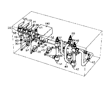
of valves.
[0025] FIG. 6 is a simplified block diagram of a sixth embodiment of a
fluid sterilization
assembly in accordance with the present invention, incorporating a cooling
section and an
inductive heat exchanger as a heating element.
[0026] FIG. 7 is a simplified block diagram of a seventh embodiment of a
fluid
sterilization assembly in accordance with the present invention, incorporating
a cooling section
and an alternate possible arrangement of valves and sensors.
[0027] FIG. 8 is a simplified block diagram of an eighth embodiment of a
fluid
sterilization assembly in accordance with the present invention, incorporating
a pre-heating
section as well as a cooling section.
[0028] FIG. 9 is a simplified block diagram of a ninth embodiment of a
fluid sterilization
assembly in accordance with the present invention, incorporating a surface
heat exchanger as a
heating element.
[0029] FIG. 10 is a simplified block diagram of a tenth embodiment of a
fluid
sterilization assembly in accordance with the present invention, incorporating
immersion heat
exchangers as heating apparatus.
CA 02996624 2018-02-26
WO 2017/040321 PCMJS2016/049081
[0030] FIG. 11 is a simplified block diagram of an eleventh embodiment of a
fluid
sterilization assembly in accordance with the present invention, incorporating
a propane-based
heater and thermoelectric generators.
[0031] FIG. 12 is a simplified block diagram of a twelfth embodiment of a
fluid
sterilization assembly in accordance with the present invention, incorporating
an autoclave
chamber with electric immersion heaters.
[0032] FIG. 13 is a perspective view of a thirteenth embodiment of a fluid
sterilization
assembly in accordance with the present invention, incorporating a controller
to read sensors and
actuate valves.
[0033] FIG. 14 is a front view of the fluid sterilization assembly depicted
in FIG. 13.
[0034] FIG. 15 is a top view of the fluid sterilization assembly depicted
in FIG. 13.
[0035] FIG. 16 is a rear view of the fluid sterilization assembly depicted
in FIG. 13.
[0036] FIG. 17 is a bottom view of the fluid sterilization assembly
depicted in FIG. 13.
[0037] FIG. 18 is a different perspective view of the fluid sterilization
assembly depicted
in FIG. 13.
[0038] FIG. 19 is a top view of one configuration of the propane-based
heater utilized in
the embodiment depicted in FIG. 11.
[0039] FIG. 20 is a variation on the embodiment depicted in FIG. 2 using a
bifurcated
immersion heater system.
[0040] FIG. 21 is a simplified block diagram of system operation in
accordance with the
invention, e.g., with reference to the assembly of FIG. 9.
[0041] FIG. 22 is a perspective view of another embodiment of a fluid
sterilization
assembly in accordance with the present invention, incorporating a gas heater.
6
CA 02996624 2018-02-26
WO 2017/040321 PCMJS2016/049081
[0042] FIG. 23 is a simplified block diagram of machine states for system
operation in
accordance with the invention.
[0043] FIG. 24 is a side view of a propane-based heater that can be used in
a heater
assembly of a fluid sterilization assembly in accordance with the invention.
[0044] FIG. 25 is a side view of another propane-based heater that can be
used in a heater
assembly of a fluid sterilization assembly in accordance with the invention.
[0045] FIG. 26 is an exemplary screenshot of a status monitoring screen of
the fluid
sterilization assembly of FIG. 22.
[0046] FIG. 27 is a simplified flow chart of system status operations of
the fluid
sterilization assembly of FIG. 22.
DETAILED DESCRIPTION OF THE PREFERRED EMBODIMENTS
[0047] The term "fluid" as used herein is defined to include any gas or
liquid capable of
flowing through the system, including water or aqueous solutions such as juice
or milk, and
liquids or gases with dissolved or suspended solids such as flue gas or crude
oil or wastewater,
e.g., black water or grey water.
[0048] Referring now to the drawings, and particularly FIGS. 1 and 2, there
is shown a
fluid sterilization assembly usable for sterilizing water. A fluid source 10
is connected to an inlet
of the assembly. The system uses high temperature to sterilize the fluid to a
desired level. This
sterilized fluid then has a variety of uses, one of which being the production
of decontaminated
drinking water no matter the level of biological contamination or source.
Sterilization is
achieved by passing the fluid through a heating element to super heat the
fluid to such a degree
as to sterilize any living transmissible agents. The system operates within
prescribed ranges for
pressure and temperature to achieve the desired level of sterilization without
need of maintaining
a fixed temperature or a fixed pressure within any portion of the system,
including the heating
section. Moreover, inlet pressure of the fluid enables flow through the
system.
[0049] Operation of the assembly can include a start-up phase, a continuous
flow phase
and an operations phase. In the start-up phase, fluid is initially introduced
into the system,
7
CA 02996624 2018-02-26
WO 2017/040321 PCT/1JS2016/049081
sterilized, resides for a short time, and primes the system for continuous
flow operation. In the
operations phase, sterilized fluid is directed for use, e.g., see FIG. 23 for
various operational
states for the assembly.
[0050] The assembly in FIGS 1 and 2 contains an inlet for the fluid, which
comprises a
valve assembly 11. The fluid continues along the flow path to a first (cool)
path portion of a heat
exchanger 12, in which the fluid is pre-heated, before it travels along the
flow path to a heating
section 14, where the fluid is heated to a prescribed temperature and pressure
for a prescribed
duration (e.g., dwell time) to sterilize the fluid to above a desired level.
Thereafter, the fluid then
travels along the flow path back through a second (hot) path portion of the
heat exchanger 12 to
cool before it exits the system. During the start-up phase, fluid exits the
system through valve
assembly 18 as off-spec discharge 19. During the operation phase, the fluid
exits the system
through valve assembly 17 as sterile fluid discharge 20. Discharge of fluid
from the system can
create a draw of more fluid into the system, to contribute to flow of
contaminated fluid into the
system, and discharge of sterilized fluid. Moreover, inlet pressure of the
fluid enables flow
through the system.
[0051] The exemplary embodiment utilizes several valves of different types
at several
dispositions in order to maintain a desired operating range of process
variables, such as flow rate
or pressure. The specific number, use, and disposition of valves in the
embodiments herein is
described for illustrative purposes only, and is not to be understood as
limiting the present
invention to these specific numbers, uses, or dispositions of valves. Various
types of valves,
including the check valves, proportional flow valves, solenoid valves, and
relief valves described
in the exemplary embodiment, may be added or removed at various dispositions
in the system
with similar functionality. For example, servo valves may be used in place of
or in addition to
latch valves described in the exemplary embodiment, and may be disposed
anywhere along the
flow path of the system, or may be eliminated from the system altogether. As
another example,
stepper motor proportional flow valves may be used in place of or in addition
to pilot-operated
proportional flow valves, used with or without pressure transducers or flow
meters.
Furthermore, the valves in the system may be actuated by hand, by spring, by
solenoid, or by any
other means of valve actuation. Similarly, the number and disposition of
thermocouples,
pressure transducers, and process sensors or other control-related apparatus
other than valves
8
CA 02996624 2018-02-26
WO 2017/040321 PCMJS2016/049081
may be altered from the descriptions herein without departing from the scope
of the present
invention. Moreover, the heating components can be insulated to inhibit
radiant heat loss.
Various forms of insulation can be used, such as, e.g., ceramic layer can be
used, which can
provide additional benefits. For example, immersion heaters can be provided
with a ceramic
coating, which can further inhibit scaling (build up) on the heaters, over
extended use.
[0052] A controller or controllers 180, disposed internally or connected
externally to the
system, interfaces with the valves, transducers, thermocouples, or sensors in
the system. The
controller 180 in the exemplary embodiment is a digital computer comprised of
a microprocessor
that executes computer readable instructions to coordinate the operation of
the system; however,
any device capable of process control may be used, including, but not limited
to, mechanical or
pneumatic controllers, or analog electronic systems. The use of controllers
could enable an
operator to observe and manage the sterilization process (e.g., reading sensor
data from a user
interface or display, and opening or closing valves accordingly), or could
enable the system to
operate autonomously under prescribed operational guidelines. Controllers may
be used to a
limited degree, or may be used to such an extent that the system would merely
need to be
powered on in order to produce sterilized fluid according to specification.
Embodiments of the
system may be used without controllers, however, such that an operator could
manually actuate
valves and read sensors information, i.e., gauges or visual readouts or
graphics.
[0053] More particularly, and with continued reference to FIG. 2, fluid
enters the system
from the inlet 30 through a hand valve (HV1) 31. In the exemplary embodiment,
the fluid has a
pressure between 50 psig and 500 psig, and travels through a check valve (CV1)
35, a pressure
transducer (P1) 36, a thermocouple (TC1) 37, and a flow meter (FM1) 38.
Additionally or
alternatively, a pump 34 may be used to draw fluid from a reservoir or other
source of
unpressurized fluid through an inlet 32. Check valves are used to ensure
unidirectional flow in
the system, and pressure transducers and thermocouples, as well as other
sensors, are used to
monitor the dynamic properties of the fluid in the system. Flow meters are
used to determine the
rate of fluid passing through the system, which can be altered using
proportional flow valves.
The inlet fluid pressure defines the flow rate and the residence time at the
sterilization
temperature, according to the applicable sterilization temperature. Table 1,
below, lists
sterilization temperatures for given inlet pressure in an exemplary
embodiment.
9
CA 02996624 2018-02-26
WO 2017/040321 PCMJS2016/049081
TABLE 1
Inlet Pressure (psig) Boiling Point ( C) Sterilization Temperature ( C)
10 115 108
50 147 140
100 170 163
200 198 191
300 216 209
400 231 224
500 254 243
[0054] As the fluid enters the system, it may pass through a filter (F1)
130 (FIG. 6) for
solid contaminants removal, before continuing into the heat exchanger 12. The
heat exchanger
12 both (a) preheats fluid prior to entering the heating section 14 and (b)
cools outflow of the
heating section 14, by enabling heat transfer therebetween. In the exemplary
embodiment, fluid
enters the system at ambient, typically between 15 C and 20 C, as measured by
TC1 37 disposed
along the flow path between the inlet 30 and the heat exchanger 12. The fluid
then flows
through the heat exchanger 12, in which it is preheated to a temperature
between approximately
70 C and 95 C, and more preferably between 88 C and 92 C, or approximately 90
C In the
event the ambient inlet temperature is lower than 15-20 C, a preheat section
may be
incorporated.
[00551 The system provides a flow path operable in a continuous and/or
batch manner
from the inlet 10 to the outlets 17, 18. The flow path comprises components
and pipes
configured to maintain the fluid at the prescribed pressure and temperatures.
In the exemplary
embodiment, food-grade stainless steel piping is used in the system, from the
inlet to the outlets,
including the heating section. The choice of metal used in the materials
throughout the system
will be based on the requirements which best suit the particular application,
but typically will be
a high temperature alloy. This permits ease of installation with typical
apparatus without
creating a metal mismatch that could produce corrosion of the metal, due
perhaps to chemical or
electrochemical reactions within the system.
CA 02996624 2018-02-26
WO 2017/040321 PCMJS2016/049081
[0056] In another embodiment, variable speed pumps can be used to achieve a
desired
pressure in the system. For example, a variable speed pump can be used
proximate to the inlet of
the system 30 to achieve a desired inlet pressure. In addition, a variable
speed pump can be
placed proximate to an outlet of the system and operated in association with
the inlet pressure to
achieve a desired outlet pressure, but not create an internal pressure upset.
[0057] In another embodiment, best seen in FIG. 5, a heating element 112 is
used to pre-
heat the fluid to an even greater temperature after it leaves the heat
exchanger 12. After passing
through this first heating element 112 (e.g., tape heaters) in the pre-heating
section 111, the fluid
then flows into the heating section 14 and through the heating apparatus
therein 113, to be
brought up to its desired temperature for sterilization. As shown in FIG. 8,
heater tape is used as
the pre-heating element 112 in this embodiment, although other heating
apparatus may be used,
similar to the primary heating section 14 as discussed below. This pre-heating
section 111 heats
the fluid to a temperature between approximately 90 C and 120 C, as measured
by a second
thermocouple (TC2) 42 disposed along the flow path between the heat exchanger
12 and the
heating section 14. Other embodiments are envisioned, however, in which fluid
passes directly
from the heat exchanger 12 to the heating section 14, or even directly from
the inlet 30 to the
heating section 14, obviating a pre-heating section 111.
[0058] A relief valve (RV1) 41 is disposed along the flow path between the
heat
exchanger 12 and the heating section 14 so as to release fluid from the flow
path if the pressure
in the flow path exceeds a set cracking pressure (e.g., 500 psig). The
actuation of a relief valve
diverts fluid out of the flow path so that the pressure in the flow path will
stop rising or decrease,
in order to protect the system from damage or failure from excessive pressure.
If actuated, the
relief valves may divert excess fluid back to the system through an auxiliary
flow path, or may
divert excess fluid out of the system.
[0059] The heating elements are configured to bring the fluid up to the
desired
temperature quickly and accurately. In the exemplary embodiment, shown in FIG.
2, the heating
section 14 utilizes immersion fluid heaters 47, 49, and 51, e.g., 1000-watt,
as the primary heating
element. Other embodiments described herein may use inductive heat exchangers
132 (FIG. 6),
surface heat exchangers 145 (FIG. 8), or propane heaters 160 (FIGS. 11, 19,
24, and 25).
11
CA 02996624 2018-02-26
WO 2017/040321 PCMJS2016/049081
However, other heating apparatus may be used, singly or in combination,
without departing from
the scope of the invention, such as tape heaters, heating rods, direct flame
(e.g., using natural
gas, propane, firewood or other fuels), immersion heaters, graphene (e.g., as
a conductor or to
administer direct heat or both), microwave, solar heaters (e.g. lenses or
mirrors to concentrate
heat energy), or heat from combined heat and power generators.
[0060] In addition, systems in accordance with the invention can be
integrated into other
mechanical structures, utilizing heat sources available therein to provide a
heat source for the
heating section. For example, the heating section can utilize heated
components of a motorized
vehicle or generator (e.g., the engine block or tailpipe) as a surface heater,
so long as the desired
heat can be achieved. In an exemplary embodiment, the heating section can
include a flow path
incorporated into a manifold integrated with heated components of a motor
component such as a
generator or vehicle (e.g., the engine block or tailpipe), in which the
controller can manage flow
rate through the heating section to maintain fluid at a prescribed temperature
and pressure for a
prescribed duration (e.g., dwell time) to sterilize the fluid. Notably, in
this embodiment,
temperature and pressure within the heating section can be monitored and
sterilization controlled
by fluid pressure and flow, throughout operation, while integrating the
temperature of the heat
supply that is dependent on operation of the motorized component.
[0061] With continued reference to FIG. 5, upon exit from the heat
exchanger 12, pre-
heated fluid is released into the heating section 14 by way of a second check
valve (CV2) 43.
Fluid is heated to between approximately 135 C to 240 C, measured by
thermocouples (TC3,
TC4, etc.) 48, 50, 52, disposed in the heating section 14 The dwell time of
fluid at 240 C is
approximately 1 second or less, although the dwell time can be altered as
needed to sterilize fluid
under different process variables.
[0062] In the exemplary embodiment, fluid is not allowed to change out of
liquid state.
By means of high-pressure containment, the fluid is allowed to reach high
temperatures while
still being maintained in a liquid state. The fluid does not need to be
maintained in a liquid state,
however, especially in embodiments that are not designed with high-pressure
flow paths. The
system is configured to heat the fluid at corresponding pressure levels to
achieve effective
sterilization. More particularly, the system can reach desired levels to
sterilize bacteria, viruses,
12
CA 02996624 2018-02-26
WO 2017/040321 PCMJS2016/049081
and prions, among other infective agents and organic pollutants. Furthermore,
above a
prescribed temperature, the system can break down organic molecules.
[0063] Another embodiment is envisioned in which a distillation component
is disposed
along the flow path, additionally or alternatively to a heating section 14.
One example of such a
distillation component could be a vacuum chamber, which would be evacuated
prior to fluid
entering the chamber, in which fluid vaporizes when it enters the low pressure
zone in the
chamber. This vaporized fluid would be collected as distillate at a condenser
before continuing
in the system. Additionally, this distillation component can be heated to
sufficiently high
temperatures as in a heating section 14, in order to function both as a
distillation component and
as a sterilization component.
[0064] The immersion water heaters 47, 49, and 51, depicted in the
embodiment in
FIG. 2 are designed to sufficiently fill the volume of the flow path in close
proximity with the
inner wall of the pipe(s) that define flow path through the heating section
(heaters 47, 49, and
51), in order to provide adequate surface area for the fluid to maintain the
desired contact with
the surface of the heaters 47, 49, and 51, to ensure that the fluid is
sufficiently heated while
guarding against overheating of the heaters. For example, in an exemplary
embodiment, the
flow over the surface of the immersion heater can match the current to the
heater or the heater
will over heat if the control is set to the exit temperature of the water, but
the flow is low and not
removing adequate heat from the heater. One method of controlling this is to
provide
thermocouples on the immersion heaters to ensure that they do not overheat if
the water flow
drops or is reduced
[0065] More particularly, the immersion heaters may have an elongated,
cylindrical
shape, wherein the heaters are oriented in axial alignment with the
cylindrical pipes that define
the flow path through the heating section In this manner, the system optimizes
energy transfer
between the heater(s) and the fluid. The flow path in the heating section 14
can incorporate
various means of increasing the efficiency of the heating element 12 as may be
required by a
particular embodiment. For example, turbulence generators such as, baffles or
turbulators, may
be disposed in the heating section 14 flow path to break the boundary layer of
the fluid's
otherwise laminar flow, or to increase the fluid's surface area that is in
direct contact with the
13
CA 02996624 2018-02-26
WO 2017/040321 PCT/1JS2016/049081
heating element 12. As another example, an internal turbulator running the
length of the heating
section 14 flow path may itself be heated as an immersion heater or as an
inductive heat
exchanger. Furtheiniore, the dimensions of the heating section 14 in any
particular embodiment
can be altered to suit the desired output quantities. For example, the length
of the heating section
14 can be decreased for a more compact or portable system embodiment, or the
diameter of the
flow path therein 14 can be increased for a larger and higher-capacity system
embodiment. Any
dimensions can be scaled up or down to attain the desired operating variables.
[0066] The heated fluid, now sterile, exits the heating section 14 and
travels back to the
heat exchanger 12. In the exemplary embodiment, the heat exchanger 12 is multi-
piped,
allowing for the compartmentalized flow of fluid entering from the inlet 30,
and heated fluid
entering from the heating section 14. The proximity of the unheated fluid
entering the heat
exchanger 12 from the inlet 30 aids the process of cooling the heated fluid
entering from the
heating section 14, but the compartmentalization prevents any possible
recontamination. In other
embodiments, other means of heat transfer and heat exchanger design can be
used without
departing from the invention. For example, plate-based heat exchangers or
phase-change heat
exchangers may be used, singularly or in combination, instead of or in
addition to tubular heat
exchangers.
[0067] In this exemplary embodiment, the temperature of the sterile fluid
is reduced to
approximately 70 C after passing through the heat exchanger 12. Another
embodiment, seen in
FIG. 6 and FIG. 7, incorporates a cooling section 135, comprising fluid
cooling apparatus 138, to
further reduce the temperature of the sterile fluid before exiting the system
The fluid is passed
through another relief valve (RV2) 54 (FIG. 2) and a stepper motor
proportional flow valve
(SIVIPFV1) 57, before being directed through either a latch valve (LV2) 58 for
off-spec discharge
19, or a latch valve (LV1) 60 for sterile fluid discharge 20 to exit the
system. Alternatively or
additionally, one three-way valve 118 (FIG. 6) could be used to direct fluid
to either the off-spec
discharge 19 or sterilized fluid discharge 20 flow path. The off-spec
discharge 19 may be
directed to exit the system, or may be directed back into the system for re-
sterilization.
[0068] Although the exemplary embodiment has been described as utilizing a
pump 34 to
ensure adequate pressure at the inlet 30, the system can be used without
pumps, as seen in FIG. 9
14
CA 02996624 2018-02-26
WO 2017/040321 PCMJS2016/049081
and FIG. 10 wherein the fluid is introduced via any of several pressure
systems, i.e., gravity feed
from storage tower, or elevated reservoir. When fluid reaches the prescribed
sterilization
temperature (e.g., 250 C), as read by TC3 48 and TC4 50, a solenoid valve
(SV1) 150 for off-
spec discharge 19 is opened, and the inlet 30 is opened at the first
proportional flow valve
(PFV1) 110. Pressure is controlled by adjustments to PFV1 110 and the second
proportional
flow valve (PFV2) 116. This creates a steady flow of fluid from inlet 30 to
discharge 19. Once a
steady flow of fluid is established for a prescribed period of time in the
heating section (e.g.,
dwell time) in order to ensure complete sterilization (e.g., 5 seconds),
without significant
temperature loss (e.g., at least 240 C maintained), as monitored by TC3 and
TC4, then SV1 150
for off-spec discharge 19 is closed and a second solenoid valve (SV2) 151 for
sterile fluid
discharge 20 is opened. Sterile fluid is then being produced, taken in at the
inlet 30 through a
HV1 31, CV' 35, and PFV1 110, exiting through SV2 151 Although the embodiments
herein are
described in detail with reference to continuous operation or to a steady flow
of fluid, other
embodiments in accordance with the invention can be operated in a pulse or
batch mode. For
example, a controller 180 could be programmed to produce sterilized fluid for
a given volume
(e.g. 100 gallons) or a given duration (e.g. 1 hour) and then shut off the
system. As another
example, a manual operator could open the requisite valves to allow a certain
volume of fluid
into the heating section 14, then close the requisite valves for the desired
dwell time to sterilize
the volume of fluid in the heating section 14, and finally open the requisite
valves to direct that
volume of fluid to the sterile fluid discharge 20
[0069] With reference now to FIG. 21, an exemplary sequence of operation of
a system
(e.g., system (FIG. 9)) in accordance with the invention is discussed. First,
in the exemplary
embodiment, the operator verifies the system is operational, as discussed in
detail below, and all
valves are closed. Next, verified the water source is attached to deliver
water to the system.
Step 3, the terminal valves can now be opened (e.g., HV1 HV2 HV3). Step 4, the
control
valves (e.g., PFV1, PFV2, SV1) are now opened to allow full flow through the
assembly to flush
out all air from the flow path. Step 5, close the control valves (e.g., PFV1,
PFV2, SV1). Now
fluid will be confined within the flow path of the system, free of air trapped
therein. The
controller (180) will read pressure within the system, e.g. via Pl, to ensure
that an initial
minimum pressure (e.g., at least 50 psi) is available.
CA 02996624 2018-02-26
WO 2017/040321 PCMJS2016/049081
[0070] If the measured initial minimum pressure is satisfactory, then at
Step 6, the
controller activates the water heating sections, in the exemplary embodiment,
the primary
heating section is set to the prescribed sterilization temperature. Step 7,
when the heating sector
is the prescribed sterilization temperature, (as measured, e.g., TC3, TC4),
the control valves
(e.g., PFV1, PFV2, SV1) are opened to initiate flow through the system. Next,
at step 8, once a
stable flow fluid is established through the system for a sufficient period of
time, e.g., at least 5
seconds, while maintaining a sufficient sterilization temperature, and the
valve (SV1) for the off-
spec discharge can be closed and the valves for sterilized fluid can be opened
(SV 2).
[0071] During operations, the controller 180 monitors the system to ensure
operational
safety is maintained and to ensure that the prescribed sterilization
temperatures and pressures are
maintained within prescribed tolerances. These measurements are continually
monitored
throughout operations throughout the system's for example, the temperature
within the primary
heating section is preferably between 240 C and 275 C (measured at TC3 and
TC4). Also, the
outflow temperature (measured at TC5). Pressure within the system, as measured
at P1 and P2
must be less than 500 psig. In the exemplary embodiment check browser utilized
to prevent
back pressure buildup in each section. Filter (F1) is used to filter out solid
contaminants from
entering the system. The controller monitors entry water temperature at TC1,
which is
preferably between 15 C and 20 C.
[0072] FIG. 26 depicts a screenshot 400 from the controller 180 depicting a
status
monitor for the system. The controller monitors the sensors and controls the
valves, heating
elements and other feature of the system During use, the controller ensures
that the system
operates within prescribed ranges for pressure and temperature to achieve the
desired level of
sterilization without need of maintaining a fixed temperature or a fixed
pressure within any
portion of the system, including the heating section. This further ensure safe
operation of the
system. In the exemplary embodiment, the measurements 410 depicted in
screenshot 400 are
received from sensors (TC1, TC2, TC3, TC4, P1, P2, P3 of FIG. 22). The
controller further
enables the operator to designate the sterilization set point and water flow
set point (420). The
controller continually updates its measurements and controls, e.g., as shown
in FIG. 27.
16
CA 02996624 2018-02-26
WO 2017/040321 PCT/US2016/049081
[0073] FIG. 13 through FIG. 18 depict several views of an embodiment
utilizing a
controller 180. FIG. 13 shows the system from the perspective of the front
upper right corner.
FIG. 14 shows the system from the front, while FIG. 15 shows the system from
the top.
Similarly, FIG. 16 shows the system from the rear, while FIG. 17 shows the
system from the
bottom. Finally, FIG. 18 shows the system from the rear lower right corner. In
this embodiment,
the system incorporates a plurality of valves coupled to the controller 180,
including valves
disposed at inlet and outlet points of the heat exchanger 12 and at inlet and
outlet points of the
heating section 14. The valves are operated in a controlled sequence to enable
effective
operation of the system to include maintaining fluid within the heating
section 14 for the desired
duration to achieve sterilization. Thereafter, inlet and outlet ports are
opened in a sequenced
manner to enable the fluid to exit the heating section 14 while creating a
draw received fluid
from the heat exchanger 12 into the heating section 14. In this manner, the
system can be
operated free of pumps, while achieving the desired pressure levels due at
least in part to control
them sequence operation of the valves via the controller 180.
[0074] With reference now to FIG. 3, a bifurcated fluid sterilization
assembly, usable for
sterilizing water, is shown similar to the aforementioned embodiments, further
including
multiple flow paths 81, 82, 83, 84, 86, 87, 88, and 89, running in parallel
through the heat
exchanger 12 and the heating section 14. Along each of the flow paths is
disposed a plurality of
valves, such that each flow path can be operated in an independent manner.
Operation of each of
the flow paths, however, can be sequenced such that continuous simultaneous
operation can be
achieved by the assembly, thereby amplifying the flow throughput of the
overall system.
Moreover, the controllable operation of the parallel flow paths enables users
to tailor the
system's output to satisfy users demand levels in real time. Other embodiments
can utilize
bifurcated or unbifurcated flow paths as necessary to achieve different
outputs. For example,
FIG. 20 depicts a variation on the embodiment in FIG. 2 using immersion
heaters 47, 49, 51, and
200, disposed along bifurcated flow paths in the heating section 14.
[0075] With reference now to FIG. 4, the assembly can further include an
autoclave
chamber 100 to sterilize equipment or supplies (e.g., medical, surgical, such
as drills, scalpels
etc.). More particularly, the autoclave chamber 100 is configured to expose
equipment to
pressurized fluid maintained above thresholds for temperature and pressure for
a prescribed
17
CA 02996624 2018-02-26
WO 2017/040321 PCT/1JS2016/049081
duration (e.g., dwell time) to achieve desired levels of sterilization, while
maintaining the fluid in
a liquid state. The autoclave chamber 100 provides an enclosure for receiving
the equipment,
which can be flooded with the pressurized fluid received from the heating
section 14 for
sterilization. The autoclave chamber 100 is coupled to the heating section 14
of the assembly to
receive pressurized fluid outflow therefrom. Additional heating apparatus,
170, 171, and 172
(FIG. 12), can be included in the autoclave unit 100 to ensure a consistent
temperature of the
fluid or to aid with drying of sterilized equipment.
[0076] In use, equipment is placed in the autoclave chamber 100. The
chamber 100 is
then pressurized, filled with pressurized fluid from the heating section 14.
Preferably, the fluid is
above a minimum temperature (e.g., 141 C), and above a minimum pressure to
maintain liquid
state. The equipment is exposed for a prescribed duration (e.g., dwell time)
to ensure
sterilization. Thereafter, fluid is drained from the autoclave chamber 100,
and sterile fluid
cooled from the heat exchanger 12 may be directed into the chamber 100 to cool
the equipment.
The chamber 100 is then drained of fluid, and the sterilized equipment can be
removed.
[0077] The outflow from the autoclave chamber 100 can be recirculated
through the
system. In the exemplary embodiment, the outflow is directed back to the heat
exchanger 12 so
that it can be recirculated to the heat exchanger 12 and the heating section
14. Alternatively, the
outflow can be directed through an off-spec discharge 19 or, since the fluid
used to sterilize the
equipment in the autoclave chamber is sterile, through a sterile fluid
discharge 20. With
reference now to FIG. 5, a perspective view is shown of a sterilization
assembly in accordance
with the invention. The system can be coupled to a fluid source and electrical
power and
thereafter can quickly initiate operations. Notably, this assembly is compact
and lightweight
such that it can be transported with ease to virtually any location. In this
manner, sterilized fluid
can be made widely available. The embodiment depicted in FIG. 5 measures less
than 1 foot in
height, less than 6 feet in length, and approximately one foot in width,
although even smaller
assemblies are possible. Alternatively, even larger assemblies are possible
with which to provide
increased sterilization capabilities.
[0078] A sterilization assembly embodiment may utilize various power
sources. One
configuration may include lithium ion batteries or other forms of energy
storage with which to
18
CA 02996624 2018-02-26
WO 2017/040321 PCT/US2016/049081
operate the sterilization assembly, or at least to operate any electronic
equipment therein. Solar
panels may be incorporated to charge said batteries or to operate a controller
180 or other
electronic equipment. Another configuration, seen in FIG. 11, incorporates
theimoelectric
generators (TEG1, TEG2, TEG3, and TEG4) 162, 163, 164, and 165, in the heating
section 14 to
recover some of the excess heat generated by the propane heating element 160
and 161 therein,
and convert it to electricity to operate the assembly's electronic equipment.
The assembly can
include a plurality of batteries. In use, a subset of the plurality of
batteries can be charging while
other batteries can be powering the assembly, thereafter alternate, once the
batteries are charged.
The controller can be configured to manage the batteries in this manner.
[0079] FIG. 18 depicts a more detailed diagram of the gas heater assembly
161
represented in FIG. 11, such that the fluid enters a coiled loop flow path 196
(FIG 19), which is
situated above a matching flow path for propane or other fuel 195, flowing
into the coil, 190, the
latter path having regularly spaced perforations 194 out of which the fuel is
directed and ignited
in order to heat the fluid in the upper flow path 196. See also FIG. 22 for
another example of an
assembly incorporating a gas heating source. FIGS. 23 and 24 depict gas heater
assemblies that
incorporate a coiled loop flow path configured in a frusto-conic
configuration, situated above a
matching flow path for propane or other fuel, the latter path having regularly
spaced perforations
out of which the fuel is directed and ignited in order to heat the fluid in
the upper flow path.
[0080] Another embodiment is envisioned in which a sterilization system,
incorporating
a system controller 180, includes a means for transmitting or receiving
information regarding the
system. For example, a controller 180 in the system could be connected to a
network to transmit
sensor data to, and receive commands from, a remote operator. As another
example, a controller
180 in the system may be equipped to broadcast an electromagnetic signal
(e.g., radio waves) to
transmit operational status, output rate, or maintenance needs (e.g.,
readiness, system state of
health) in order to monitor the system remotely.
[0081] It should be appreciated from the foregoing that the present
invention provides a
system and method of fluid sterilization which incorporates a heating
apparatus to heat
pressurized fluid above prescribed thresholds for temperature, pressure, and
duration (e.g., dwell
time) to achieve desired levels of sterilization, including a heat exchanger
to both (a) preheat
19
CA 02996624 2018-02-26
WO 2017/040321 PCMJS2016/049081
fluid prior to entering the heating apparatus and (b) cool outflow of the
heating apparatus, and in
which fluid travels through the apparatus by operating valves forward and aft
of the heating
section in a controlled sequence to facilitate flow through the system while
maintain prescribed
pressure and temperature profiles. The system operates within prescribed
ranges for pressure
and temperature to achieve the desired level of sterilization without need of
maintaining a fixed
temperature or a fixed pressure within any portion of the system, including
the heating section.
Moreover, embodiments in accordance with the invention can be tailored for
residential,
business, or industrial uses, as desired.
[0082] The present invention has been described above in terms of presently
preferred
embodiments so that an understanding of the present invention can be conveyed.
However, there
are other embodiments not specifically described herein for which the present
invention is
applicable. Therefore, the present invention should not to be seen as limited
to the forms shown,
which is to be considered illustrative rather than restrictive.