Note: Descriptions are shown in the official language in which they were submitted.
CA 02996862 2018-02-27
WO 2017/044317 PCT/US2016/048644
- 1 -
CONTAINER WITH PRESSURE ACCOMMODATION AREA
BACKGROUND
Field
[0001] The present disclosure relates to containers.
BRIEF SUMMARY
[0002] In some embodiments, a container comprising a body portion is
provided. The
body portion includes a flat upper vacuum panel, a flat lower vacuum panel,
and a recess
between the flat upper vacuum panel and the flat lower vacuum panel. In
response to a
change in the internal container pressure, the body portion flexes at the
recess towards an
interior of the container and the flat upper vacuum panel and the flat lower
vacuum panel
form a progressively smaller angle at the recess in response to an increasing
pressure
change.
[0003] In some embodiments, the recess is a living hinge that connects the
flat lower
vacuum panel and the flat upper vacuum panel. In some embodiments, the hinge
comprises two connecting sidewalls forming an angle, wherein the angle
decreases as the
hinge flexes. In an embodiment, the flat upper vacuum panel and the flat lower
vacuum
panel flex in towards the interior of the container after the flexing of the
hinge.
[0004] In some embodiments, the flat upper vacuum panel and the flat lower
vacuum
panel are co-planar prior to flexing and move out of plane to form the
progressively
smaller angle at the hinge.
[0005] In some embodiments, the flat upper vacuum panel and the flat lower
vacuum
panel together have a height that is at least 30% of a total height of the
container.
[0006] In some embodiments, at least one of the flat upper vacuum panel
and the flat
lower vacuum panel has a height that is at least 15% of a total height of the
container.
[0007] In some embodiments, wherein the container has an initial volume,
and flexing of
the hinge, the flat upper vacuum panel, and the flat lower vacuum panel
decreases the
initial volume by 3%. In some embodiments, the flexing of the hinge, the flat
upper
vacuum panel, and the flat lower vacuum panel decreases the initial volume by
5%.
CA 02996862 2018-02-27
WO 2017/044317 PCT/US2016/048644
-2-
100081 In some embodiments, the flat upper vacuum panel and the flat lower
vacuum
panel remain flat while flexing.
[0009] In some embodiments, the recess comprises a valley with an angled
sidewall.
[0010] In some embodiments, the body portion has an oval cross-section.
[0011] In some embodiments, the container further comprises a neck portion
with a
cross-sectional circumference, a shoulder portion with a cross-sectional
circumference,
and a base portion with a cross-sectional circumference. The shoulder portion
is
connected to the neck portion and the body portion extends from the shoulder
portion to
the base portion. The shoulder portion is also connected to the neck portion.
In some
embodiments, the shape of the cross-sectional circumference of the body
portion at the
recess changes more relative to the other cross-sectional circumferences in
response to the
increasing pressure change.
[0012] In some embodiments, the shoulder portion has a cross-sectional
circumference
that is greater than a cross-sectional circumference of the body portion.
[0013] In some embodiments, the flat upper vacuum panel and the flat lower
vacuum
panel are co-planar before flexion.
[0014] In some embodiments, the body portion further comprises a scalloped
region
extending circumferentially adjacent to the upper vacuum panel, the lower
vacuum panel,
and the recess. In some embodiments, the scalloped region flexes outwardly in
response
to the change in internal container pressure.
[0015] In some embodiments, the container is a bottle.
[0016] In some embodiments a container is provided. The container
comprises a neck
portion defining a container opening, a shoulder portion connected to the neck
portion,
and a body portion extending from the shoulder portion to a base portion. The
body
portion comprises two pressure accommodation areas and two vertical ribbed
areas. Each
pressure accommodation area includes a first flat panel, a second flat panel,
and a groove
connecting the first flat panel and the second flat panel. The groove of each
pressure
accommodation area moves in towards an interior of the body in response to a
change in
pressure within the container.
[0017] In some embodiments, the body portion has an oval cross-section and
the groove
of one pressure accommodation area is disposed diametrically opposite the
groove of the
other pressure accommodation area.
CA 02996862 2018-02-27
WO 2017/044317 PCT/US2016/048644
-3-
100181 In some embodiments, the pressure change is caused by a cooling of
a liquid
contained within the container.
[0019] In some embodiments, the pressure change is caused by a pressure
applied to an
exterior of the container.
[0020] In some embodiments, the container includes no more than two of the
pressure
accommodation areas.
[0021] In some embodiments, a container for storing a liquid filled in a
hot state and then
sealed is provided. The container comprises a neck portion defining a
container opening,
a shoulder portion connected to the neck portion, and pressure accommodation
area
coupled to the shoulder portion, wherein the pressure accommodation area
comprises a
flat area horizontally bisected by a valley. When the container is sealed, the
pressure
accommodation area is configured to flex away from its original shape towards
an interior
of the container, and when the seal is released, the pressure accommodation
area is
configured to return to its original shape.
[0022] In some embodiments, the flex is initiated by cooling of the
liquid.
BRIEF DESCRIPTION OF THE DRAWINGS/FIGURES
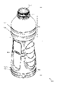
[0023] FIG. 1 is a perspective top view of a container according to some
embodiments.
[0024] FIG. 2 is a perspective bottom view of a container according to
some
embodiments.
[0025] FIG. 3 is side view of a container with a pressure accommodation
area according
to some embodiments.
[0026] FIG. 4A is a cross-sectional view of the container of FIG. 3 at
line A-A.
[0027] FIG. 4B is a cross-sectional view of the container of FIG. 3 at
line B-B.
[0028] FIG. 4C is a cross-sectional view of the container of FIG. 3 at
line C-C.
[0029] FIG. 4D is a cross-sectional view of the container of FIG. 3 at
line D-D.
[0030] FIG. 4E is a cross-sectional view of the container of FIG. 3 at
line E-E.
[0031] FIG. 5 is a side view of a container with a vertical ribbed area
according to some
embodiments.
[0032] FIG. 6A is a close-up view of area A in the container of FIG. 5.
[0033] FIG. 6B is a close-up view of area B in the container of FIG. 5.
[0034] FIG. 6C is a close-up of area C in the container of FIG. 5.
CA 02996862 2018-02-27
WO 2017/044317 PCT/US2016/048644
-4-
100351 FIG. 7 is a top view of a container according to some embodiments.
[0036] FIG. 8 is a bottom view of a container according to some
embodiments.
[0037] FIG. 9 is a cross-sectional view of the container of FIG. 8 at line
A-A.
[0038] FIG. 10 is a graph showing the change of different variables over
time as the
temperature of the liquid cools.
[0039] FIG. 11A is a partial view of a container according at point A of
the graph in FIG.
according to some embodiments.
[0040] FIG. 11B is a side view of the container of FIG. 11A.
[0041] FIG. 11C is a partial view of a container according at point B of
the graph in FIG.
10 to some embodiments.
[0042] FIG. 11D is a side view of the container of FIG. 11C.
[0043] FIG. 11E is a partial view of a container at point C of the graph
in FIG. 10
according to some embodiments.
[0044] FIG. 11F is a side view of the container of FIG. 11E.
[0045] FIG. 11G is a partial view of a container at point D of the graph
in FIG. 10
according to some embodiments.
[0046] FIG. 11H is a side view of the container of FIG. 11E.
[0047] FIG. 111 is a partial view of a container at point E of the graph
in FIG. 10
according to some embodiments.
[0048] FIG. 11J is a side view of the container of FIG. 11E.
[0049] FIG. 11K is a partial view of a container at point F of the graph
in FIG. 10
according to some embodiments.
[0050] FIG. 11L is a side view of the container of FIG. 11E.
[0051] FIG. 11M is a partial view of a container at point G of the graph
in FIG. 10
according to some embodiments.
[0052] FIG. 11N is a side view of the container of FIG. 11E.
[0053] FIG. 12A is a cross-sectional view of a container at the recess
before flexing
according to some embodiments.
[0054] FIG. 12B shows changes to the cross-sectional view of FIG. 12A
while flexing.
[0055] FIG. 12C shows changes to the cross-sectional view of FIG. 12A
while flexing.
[0056] FIG. 12D shows changes to the cross-sectional view of FIG. 12A
while flexing.
[0057] FIG. 12E shows changes to the cross-sectional view of FIG. 12A
while flexing.
CA 02996862 2018-02-27
WO 2017/044317 PCT/US2016/048644
-5-
100581 FIG. 12F shows changes to the cross-sectional view of FIG. 12A
while flexing.
[0059] FIG. 12G shows changes to the cross-sectional view of FIG. 12A
while flexing.
[0060] FIG. 13 is a side view of a container being gripped by a consumer
according to
some embodiments.
[0061] FIG. 14A, FIG. 14B, and FIG. 14C show representations of the angle
change
between a first vacuum panel and a second vacuum panel according to some
embodiments.
[0062] FIG. 15A, FIG. 15B, and FIG. 15C show representations of the angle
change at a
hinge according to some embodiments.
DETAILED DESCRIPTION
[0063] Drinkable fluids provided to consumers, such as juices, soft
drinks, and sports
drinks, may be bottled using a hot-fill process. With this process, the liquid
is heated to an
elevated temperature and then bottled while at that elevated temperature.
Specific heating
temperatures vary depending on the liquid being bottled and the type of
container being
used for bottling. For example, when bottling a liquid for a sports drink
using a container
made of PET, the liquid may be heated to a temperature of 83 C or higher. The
elevated
liquid temperature of the liquid sterilizes the container upon filling such
that other
sterilization processes are not needed. After the liquid is filled, the
container is
immediately capped, sealing the hot liquid inside the container. The
container, along with
the liquid inside, is then actively cooled before the container is labeled,
packaged, and
shipped to the consumer.
[0064] Despite the benefits of the hot-fill process, the cooling down of
the liquid after
filling may cause deformation of the container and stability issues. For
example, a liquid
that is heated to 83 C may be cooled down to 24 C for the labeling,
packaging, and
shipping process. The cooling of the hot liquid reduces the volume of the
liquid inside the
container. Because the container is sealed, the volume reduction of the liquid
results in a
change in the container's internal pressure such that the pressure inside the
container
becomes lower than the pressure surrounding the container. For example, the
pressure
inside the container may change such that it is 1-550 mm Hg less than the
pressure
surrounding the container (atmospheric pressure).
CA 02996862 2018-02-27
WO 2017/044317 PCT/US2016/048644
-6-
100651 As the internal pressure in the container drops, it creates a
pressure differential
(vacuum) that causes stresses to the container. If left uncontrolled, these
stresses may
result in undesirable distortion of the container shape as the container and
contents tend
toward an equilibrium state. For example, the container may distort
significantly from its
original shape so that it is difficult to label or package the container.
[0066] Thus, there exists a need for a container that may accommodate this
internal
pressure change during the bottling process so the container does not
drastically deform
from its original shape. Additionally, the container should be able to
accommodate this
change in internal pressure in a way that does not interfere with the
stability and usability
of the container. For example, the container, in its deformed shape, should
still be able to
withstand forces that may be experienced during shipment. Additionally, the
accommodation method should not interfere with a consumer's use of the
container, such
as when the consumer dispenses the liquid from the container.
[0067] Containers as described herein comprise at least one pressure
accommodation
area. The pressure accommodation area has a first vacuum panel, a second
vacuum panel,
and a recess between the first vacuum panel and the second vacuum panel. Due
to the
shape of the panels, the shape of the recess, and the connection between the
panels and
the recess, the pressure accommodation area may safely accommodate a change in
the
internal pressure of the container without causing uncontrollable distortion.
Additionally,
the pressure accommodation area disclosed herein does not interfere with the
container's
usability. In some embodiments, the pressure accommodation area contributes to
the
usability of the container.
[0068] In some embodiments, and as shown in FIG. 1, a container 1000 has a
neck
portion 200, a shoulder portion 300, a body portion 400, and a base portion
500. A
container opening 1002 allows for liquid to flow in and out of container 1000.
Container
1000 may also include a lid 600, shown in FIG. 11B, which is placed over the
neck
portion 200 after the container is filled to seal the container from the
outside environment.
Lid 600 may be removed from the neck portion 200 in order to access the
liquid.
[0069] FIG. 6B shows an up-close view of the transition between the
shoulder portion
300 and the body portion 400. In some embodiments, shoulder portion 300 is
greater in
circumference than body portion 400 and a horizontal cross-section of shoulder
portion
300 encloses a greater area than does a horizontal cross-section of body
portion 400.
CA 02996862 2018-02-27
WO 2017/044317 PCT/US2016/048644
-7-
100701 Container 1000 may be any vessel that is suitable for storing a
liquid, in which,
during storage, the internal pressure of container 1000 changes. In some
embodiments,
container 1000 is a bottle. In some embodiments, container 1000 is made of PET
(polyethylene terephthalate), but other suitable flexible and resilient
materials may be
used, including, but not limited to, plastics such as PEN (polyethylene
naphthalate),
bioplastics such as PEF (polyethylene fluranoate), and other polyesters.
[0071] Container 1000 has a height H that is measured from the beginning
of the neck
portion 200 to the end of the base portion 500. Sections 302 of shoulder
portion 300 and
sections 502 of base portion 500 are ridged, with the ridges extending around
the entire
circumference of those sections. FIG. 6A and FIG. 6C show close-up views of
ridged
sections 302 and 502, respectively.
[0072] Referring now to FIG. 2 and FIG. 3, body portion 400 of container
1000 includes
at least one pressure accommodation area 410 that is set back (recessed) from
the rest of
the body portion 400. Pressure accommodation area 410 controls the deformation
of
container 1000 during the hot-fill process such that the container maintains
its stability
and does not deform drastically.
[0073] Pressure accommodation area 410 includes a first vacuum panel 411,
a second
vacuum panel 412, and a recess 413 located between the first and second vacuum
panels
411 and 412. FIGS. 2 and 3 show the first vacuum panel 411, the second vacuum
panel
412, and the recess 413 arranged such that the first vacuum panel 411 is
directly above
the second vacuum panel 412 with the recess 413 extending horizontally between
the two
vacuum panels 411 and 412. As will be described in further detail below, this
arrangement initiates and contributes to the flexing of the first vacuum panel
411 and the
second vacuum panel 412. However, other arrangements are also envisioned so
long as
the concepts of the flexing of the first vacuum panel 411, the second vacuum
panel 412,
and the recess 413 as described herein may be achieved. For example, in some
embodiments, the recess 413 may extend horizontally for only a portion of the
width of
the first vacuum panel 411 and the second vacuum panel 412 and not the entire
width. In
another embodiment, first vacuum panel 411 may not be directly above second
vacuum
panel 412, but may be horizontally offset from second vacuum panel 412.
[0074] In some embodiments, at least one of first vacuum panel 411 and
second vacuum
panel 412 is flat. In some embodiments, both first vacuum panel 411 and second
vacuum
CA 02996862 2018-02-27
WO 2017/044317 PCT/US2016/048644
- 8 -
panel 412 are flat. Such flat surfaces may allow for less stress resistance as
compared to
other surfaces, such as ridged or curved surfaces, thereby promoting
deformation of these
flat surfaces upon an internal volume change.
[0075] In some embodiments, and as shown in FIG. 3, second vacuum panel
412 has a
height 412h that is taller than a height 411h of the first vacuum panel 411.
While FIG. 3
shows height 412h as being greater than height 411h, height 411h could be
greater than
height 412h or both heights 411h and 412h could be equal. In some embodiments,
412h
and 411h together have a height that accounts for at least 30% of container
1000's height
H. In some embodiments 412h and 411h together have a height that accounts for
at least
50% of container 1000's height H. In some embodiments, either height 411h or
412h by
itself makes up at least 15% of total height H of container 1000. In some
embodiments,
either height 411h or 412h by itself makes up at least 20% of the total height
H of
container 1000. Thus, in some embodiments, a pair of first vacuum panel 411
and second
vacuum panel 412 are prominent features of container 1000 and account for a
substantial
portion of the surface area of container 1000 (e.g., greater than 5% or
greater than 10%).
[0076] Body portion 400 of container 1000 may also include a vertical
ribbed area 420.
An embodiment of vertical ribbed area 420 is shown in FIGS. 2 and 5. As shown
in FIG.
2, vertical ribbed area 420 may be circumferentially adjacent to pressure
accommodation
area 410, extending circumferentially adjacent to first vacuum panel 411,
second vacuum
panel 412, and recess 413. Referring back to FIG. 5, in some embodiments,
vertical
ribbed area 420 may include at least one scalloped feature 421. While FIG. 2
shows three
scalloped features 421, container 1000 may include more or fewer scalloped
features.
Vertical ribbed area 420, along with the scalloped features 421, contributes
to stability of
the container during packaging and provides a grip area for the consumer. In
some
embodiments, vertical ribbed area 420 does not flex in towards the interior of
container
1000 when container 1000 deforms.
[0077] Container 1000 may have more than one pressure accommodation area
410 and
more than one vertical ribbed area 420. As shown in the Figures, in some
embodiments
container 1000 may have two pressure accommodation areas 410 and two vertical
ribbed
areas 420. In embodiments with two pressure accommodation areas 410, the
second
pressure accommodation area 410 is similar to the first pressure accommodation
area 410.
CA 02996862 2018-02-27
WO 2017/044317 PCT/US2016/048644
- 9 -
In embodiments with two vertical ribbed areas 420, the second vertical ribbed
area 420 is
similar to the first vertical ribbed area 420.
[0078] In embodiments with two vertical ribbed areas 420 and two pressure
accommodation areas 410, the four areas may be located in container 1000
anywhere
circumferentially. For example, in some embodiments second pressure
accommodation
area 410 is positioned diametrically opposite first pressure accommodation
area 410 and
first vertical ribbed area 420 is positioned diametrically opposite second
vertical ribbed
area 420. This is shown, for example, in FIGS. 11A and 12A. This arrangement
of two
diametrically opposed pressure accommodation areas 410 and two diametrically
opposed
vertical ribbed areas 420 provide container 1000 with symmetrical deflection
sides so that
container 1000 may deform in a uniform and aesthetically pleasing manner. As
will be
described later, this arrangement also allows container 1000, and more
specifically, the
horizontal cross-section of container 1000 at recess 413, to retain its
generally oval shape
throughout deformation due to the similar way the two diametrically opposed
pressure
accommodation areas 410 change in response to the change in internal pressure.
In some
embodiments, container 1000 has no more than two vertical ribbed areas 420. In
some
embodiments, container 1000 has no more than two pressure accommodation areas
410.
[0079] In some embodiments container 1000 may include more than two
pressure
accommodation areas 410 and more than two vertical ribbed areas 420. A person
of
ordinary skill in the art, with the benefit of this disclosure, could
determine an appropriate
number of pressure accommodation areas 410 and vertical ribbed areas 420 and
suitable
placement of each depending on bottle shape and design.
[0080] FIGS. 4A-4E show different cross-sections of container 1000 before
deformation
of container 1000.
[0081] FIG. 4A is a vertical cross-section of pressure accommodation area
410 along line
A-A of FIG. 3. As shown in FIG. 4A, in some embodiments, recess 413 takes the
shape
of a valley with two angled sidewalls 414A and 414B. FIG. 4A also details a
portion of
first vacuum panel 411 and second vacuum panel 412. In FIG. 4A, these vacuum
panels
are flat.
[0082] FIG. 4B is a horizontal cross-section of container 1000 along line
B-B of FIG. 3.
Thus, the cross-section of container 1000 in FIG. 4B includes pressure
accommodation
areas 410 and vertical ribbed areas 420. As can be seen in FIG. 4B, the sides
of the cross-
CA 02996862 2018-02-27
WO 2017/044317 PCT/US2016/048644
- 10 -
section representing the pressure accommodation areas 410 are slightly curved.
This is
because FIG. 4B shows a cross-section of pressure accommodation area 410 that
includes
recess 413.
[0083] FIG. 4C is a horizontal cross-section of container 1000 along line
C-C of FIG. 3.
Thus, the cross-section of container 1000 in FIG. 4C also shows two pressure
accommodation areas 410 and two vertical ribbed areas 420. FIG. 4C is
different from
FIG. 4B in that FIG. 4C shows the cross-section of pressure accommodation
areas 410 at
the second vacuum panel 412. Thus, contrary to FIG. 4C, the sides of the cross-
section
representing the pressure accommodation areas 410 are flat and not curved.
This is
because, in this embodiment, the second vacuum panel 412 is flat.
[0084] FIG. 4D is a horizontal cross-section of container 1000 along line
D-D of FIG. 3.
Thus, the cross-section of container 1000 in FIG. 4D shows pressure
accommodation
areas 410 and vertical ribbed areas 420. FIG. 4D is different from FIG. 4C in
that FIG.
4D shows the cross-section of container 1000 where the body portion 400
transitions into
the second vacuum panel 412. The cross-section representing the pressure
accommodation area 410 is indented because the second vacuum panel 412 is set
back
from the remainder of body portion 400.
[0085] FIG. 4E is a horizontal cross-section of container 1000 along line
E-E of FIG. 3.
Thus, the cross-section of container 1000 in FIG. 4E shows pressure
accommodation
areas 410 and vertical ribbed areas 420. FIG. 4E is different from FIG. 4D in
that FIG. 4E
shows the transition of the body portion 400 and the first vacuum panel 411.
The sides of
the cross-section representing the pressure accommodation areas 410 are
recessed
because the first vacuum panel 411 is set back from the remainder of the body
portion
400. FIG. 4E shows a smaller recess than FIG. 4D because, in some embodiments,
the
body portion close to first vacuum panel 411 is less protruded than the body
portion close
to second vacuum panel 412. This may also be seen in FIG. 3.
[0086] In some embodiments, and as can be seen in FIGS. 4A-4E, body
portion 400 has
a generally oval circumference across its length. As used herein, "oval"
includes a shape
with two different perpendicular diameters that act as axes of symmetry, not
accounting
for minor variation due to surface detail. For example, all of the cross-
sections in FIGS.
4A-4E may be considered as being generally oval in shape. In some embodiments,
the
container 1000 retains a generally oval shape through its deformation, even if
the original
CA 02996862 2018-02-27
WO 2017/044317 PCT/US2016/048644
- 11 -
oval shape is not retained. In some embodiments the retention of a generally
oval shape is
most prominent at the horizontal cross-section of recess 413. This may be seen
in FIGS.
12A-12G, which show the deformation of container 1000 at recess 413, along
line B-B of
FIG. 3. In some embodiments, and as seen in FIGS. 12A-12G, the original shape
is only
slightly oval, whereas the oval shape after deformation is more substantial.
[0087] Ways in which the pressure accommodation area 410 controls
deformation of
container 1000 will now be discussed in reference to FIG. 10, FIGS. 11A-11M,
FIGS.
12A-12G, FIGS. 14A-14C, and FIGS. 15A-15C.
[0088] After container 1000 is filled with hot liquid, lid 600 is placed
over the neck
portion 200, sealing the container from the environment. This is shown in FIG.
11B.
[0089] FIG. 10 shows a graph detailing the change of six different
container
characteristics over time during container deformation as the liquid cools:
change in
container 1000's overall height (H), pinch rib ovalization, standing ring
undulation,
internal container pressure, container volume, and liquid temperature.
[0090] Line 6 represents the change of the liquid temperature over time.
Line 4 represents
the change in the internal container pressure over time. As shown in FIG. 10,
as time
passes, the liquid temperature cools and the internal pressure of container
1000 drops.
FIG. 10 specifically calls out five sequential time points for reference: time
A, time B,
time C, time D, time E, time F, and time G. Characteristics at other time
points will be
apparent from the graph and accompanying explanation. FIGS. 11A-11N show
various
views of the container at those specific times. FIGS. 11A and 11B show
container 1000 at
time A. FIGS. 11C and 11D show container 1000 at time B. FIGS. 11E and 11F
show
container 1000 at time C. FIGS. 11G and 11H show container 1000 at time D.
FIGS. 111
and 11J show container 1000 at time E. FIGS. 11K and 11L show container 1000
at time
F. FIGS. 11M and 11N show container 1000 at time G.
[0091] The stippling in FIGS. 11A, 11C, 11E, 11G, 111, 11K, and 11M,
represent the
stresses felt by some portions of the container 1000 relative to other
portions of container
1000 at times A, B, C, D, E, F, and G, respectively. More stippling (e.g.,
appearing
darker) represents a relatively higher amount of stress (e.g., von Mises
stresses) than less
stippling (e.g., appearing lighter or without stippling). The legend A
provides a relative
reference for relating the depicted stippling to relatively lower and
relatively higher
stresses felt by one region of the container to the other.
CA 02996862 2018-02-27
WO 2017/044317 PCT/US2016/048644
- 12 -
[0092] The stippling in FIGS. 11B, 11D, 11F, 11H, 11J, 11L, and 11N,
represent the
degree of deformation undergone by some portions of the container 1000
relative to other
portions of container 1000 at times A, B, C, D, E, F, and G, respectively.
More stippling
(e.g., appearing darker) represents a relatively greater degree of deformation
than less
stippling (e.g., appearing lighter or without stippling). The legend B
provides a relative
reference for relating the depicted stippling to relatively lower and
relatively higher
degrees of deformation undergone by one region of the container to the other.
[0093] At time A, the liquid is still at its elevated temperature and
there has been no drop
in the internal pressure of container 1000. FIG. 11A shows a partial cross-
section of
container 1000 at time A. FIG. 11B shows a side view of the container 1000 at
time A. At
time A the container 1000 is in its original shape and is un-deformed because
there is no
change in temperature or internal container pressure. Thus, container 1000
shown in FIG.
11A and FIG. 11B do not have any stippled portions as container 1000 is not
under any
stress or and not deformed at time A.
[0094] As the temperature of the liquid cools over time, the internal
pressure of container
1000 also drops. As the internal container pressure drops, it becomes lower
than the
external surrounding pressure, creating a pressure differential (vacuum) that
causes stress
to the material of container 1000.
[0095] For example, at time B in FIG. 10, the temperature of the liquid
has cooled from
its original temperature at time A and the internal container pressure has
dropped from the
original pressure at time A. Due to its angled sidewalls, recess 413 is less
resistive to
stresses. Thus, in response to the drop in in internal container pressure,
recess 413
experiences stress before other portions of the container 1000. This is shown
in FIG. 11C
with the stippled region being only at and immediately around recess 413.
Additionally,
the pressure accommodation area 410 begins to slightly flex at recess 413
towards an
interior of the container. This is shown in FIG. 11D as the lightly stippled
area at recess
413.
[0096] As the temperature of the liquid further cools and the internal
pressure of
container 1000 further drops, for example at time C, the first and second
vacuum panels
411 and 412 start to experience stress as well. This is shown in FIG. 11E. As
compared to
FIG. 11C, the stippled area originally contained at recess 413 has spread to
the first
vacuum panel 411 and the second vacuum panel 412. As shown in FIG. 11E, recess
413
CA 02996862 2018-02-27
WO 2017/044317 PCT/US2016/048644
- 13 -
further flexes towards the interior of container 1000. This flexing causes the
flexing of the
first vacuum panel 411 and the second vacuum panel 412 towards the interior of
the
container 1000. As compared to FIG. 11D, the first vacuum panel 411 and the
second
vacuum panel 412 in FIG. 11F are further angled. The flexing of recess 413,
first vacuum
panel 411, and second vacuum panel 412 causes the pressure accommodation area
to flex
towards the interior of container 1000. This is also shown in FIG. 11E by the
line 401A
showing the original profile of the pressure accommodation area line and 401B,
showing
the deflection profile of the pressure accommodation area.
[0097] Times D, E, F, and G involve progressively cooler liquid
temperatures and
progressively decreased internal container pressures. FIGS. 11G and 11H
correspond to
time D in FIG. 10. FIGS. 111 and 11J correspond to time E in FIG. 10. FIGS.
11K and
11L correspond to time F in FIG. 10. FIGS. 11M and 11N correspond to time G in
FIG.
10.
[0098] Generally, FIGS. 11A, 11C, 11E, 11G, 111, 11K, and 11N show that
the portion of
container 1000 that experiences stress first is recess 413. The stress then
spreads to the
first vacuum panel 411 and the second vacuum panel 412. These figures also
show that
the stresses felt by the container 1000 during the cooling process are mostly
concentrated
in pressure accommodation areas 410. In some embodiments, greater than 50% of
the
stresses felt by the container 1000 during the cooling process are
concentrated in pressure
accommodation areas 410. In some embodiments, greater than 75% of the stresses
are
concentrated in pressure accommodation areas 410. In some embodiments, greater
than
90% of the stresses are concentrated in pressure accommodation areas 410.
[0099] FIGS. 11B, 11D, 11F, 11H, 11J, 11L, and 11M show that recess 413
starts to flex
towards an interior of the container 1000 before any other portion of
container 1000.
After the recess 413 flexes, the first vacuum panel 411 and the second vacuum
panel 412
start to flex towards an interior of the container 1000. FIGS. 11B, 11D, 11F,
11H, 11J,
11L, and 11M also show that the shape of the other portions of container 1000,
such as
neck portion 200, shoulder portion 300, and base portion 500, do not deform as
much
relative to the deformation experienced by the body portion 400. In some
embodiments
the shape of the other portions of container 1000, such as neck portion 200,
shoulder
portion 300, and base portion 500, do not deform at all (or not appreciably)
relative to the
deformation experienced by the body portion 400. In some embodiments, in the
body
CA 02996862 2018-02-27
WO 2017/044317 PCT/US2016/048644
- 14 -
portion 400, the horizontal cross-section that changes the most relative to
all the other
horizontal cross-sections of the body portion 400 is a cross-section taken at
recess 413.
This change is described in more detail later in relation to FIGS. 12A-12G.
[0100] FIG. 10 also shows line 3, which details the undulation of the
standing ring in
millimeters. Base portion 500 has standing ring 501, as shown in FIGS. 2, 8,
and 9.
Standing ring 501 is the bottom surface of the container 1000 upon which
container 1000
sits. Line 3 in FIG. 10 shows that, as the internal pressure of container 1000
drops, the
standing ring 501 also slightly flexes in towards the interior of the
container 1000.
[0101] The flex of standing ring 501 towards the interior of container
1000 is shown in
FIGS. 11E, 11G, 111, 11K, and 11M. Line 501A in those figures shows the
placement of
the original standing ring and line 501B shows the flexing of the standing
ring in response
to the change of internal container pressure. The amount of flex experienced
by the
standing ring 501 is small relative to the flex experienced by the pressure
accommodation
area. The difference of flexing between the standing ring 501 and the pressure
accommodation area 410 may be gauged by comparing the change between lines
401A
and 401B, and the change between lines 501A and 501B. Because the pressure
accommodation area 410 is designed to concentrate the stresses only to that
area of
container 1000, the other portions of container 1000 do not experience
substantial stress
or deformation. Thus, due to the pressure accommodation areas, the change in
shape of
the other portions due to a change in internal container pressure, including
the standing
ring 501, is relatively small. Thus, the deformation of container 1000 is
mostly contained
to body portion 400.
[0102] In some embodiments, the small deformation of other portions of
container 1000
compared to the deformation of body portion 400 may be quantified by
determining how
much that portion has flexed in towards an interior of container 1000 compared
to how
much recess 413 of body portion 400 has flexed. For example, in some
embodiments, the
amount of flex (e.g., deformation displacement) experienced by standing ring
501 after
deformation is, at most, 10% of the amount of flex experienced by body portion
400 at
recess 413 after deformation. In some embodiments, the amount of flex
experienced by
standing ring 501 is at most 5% of the amount of flex experienced by the
vacuum
accommodation area at recess 413. In some embodiments, the amount of flex
experienced
CA 02996862 2018-02-27
WO 2017/044317 PCT/US2016/048644
- 15 -
by standing ring 501 is at most 2% of the amount of flex experienced by the
pressure
accommodation areas at recess 413.
[0103] In some embodiments, the deformation displacements may be compared
by
determining what percentage of container 1000's volume reduction is
contributed to the
deformation of body portion 400.
[0104] For example, when the liquid cools, its volume is reduced (e.g., by
3-5%). Thus,
in some embodiments, the flexing of the body portion 400 decreases container
1000's
initial volume by 3%. In some embodiments, the initial volume is decreased by
5%. In
some embodiments, at least 85% of the decrease in container 1000's initial
volume is due
to the deformation of body portion 400. In some embodiments at least 90% of
the
decrease in initial container volume is because of deformation of body portion
400. In
some embodiments, at least 95% of the decrease in initial container volume is
due to
deformation of body portion 400.
[0105] In some embodiments, the structure of the recess and its connection
to the first
vacuum panel 411 and the second vacuum panel 412 initiates and contributes to
the
flexing of the first vacuum panel 411 and the second vacuum panel 412. For
example, in
some embodiments, the recess 413 acts as a living hinge connecting the first
vacuum
panel 411 and the second vacuum panel 412. Thus, as the living hinge flexes in
towards
the interior of the container 1000, it gradually pulls the first vacuum panel
411 and the
second vacuum panel 412 in towards an interior of container 1000. In some
embodiments,
the living hinge has two sidewalls 414A and 414B forming an angle 415. As the
hinge
flexes inwards, the angle 415 gets progressively smaller. This is shown in
FIGS. 15A-
15C.
[0106] FIGS. 14A¨FIG.14C schematically show an inward flexing of first
vacuum panel
411 and second vacuum panel 412. In FIG. 14A, the first vacuum panel and the
second
vacuum panel are in their original shape. They form an angle 430 at the recess
413. As
the first vacuum panel 411 and the second vacuum panel 412 flex in towards the
interior
of the container 1000 in response to an increasing change in the internal
pressure, the
angle 430 formed by the first vacuum panel 411 and the second vacuum panel 412
at
recess 413 becomes progressively smaller. It is noted that FIGS. 14A-14C are
only a
schematic representation and that the angle change as shown in these figures
is
exaggerated for clarity. In some embodiments, since deformation of pressure
CA 02996862 2018-02-27
WO 2017/044317 PCT/US2016/048644
- 16 -
accommodation area 410 is concentrated at recess 413, first vacuum panel 411
disposed
above recess 413 undergoes greater deformation at its lower end (e.g., a
degree of
deformation of first vacuum panel 411 decreases in an upward direction from
recess 413).
Similarly, second vacuum panel 412 disposed below recess 413 undergoes greater
deformation at its upper end (e.g., a degree of deformation of second vacuum
panel 412
decreases in a downward direction from recess 413).
[0107] In some embodiments, and as shown in FIG. 14A, the first vacuum
panel 411 and
the second vacuum panel 412 are co-planar to one another prior to flexing. As
the panels
flex in towards the interior of the container 1000 and form a progressively
smaller angle
at the recess, first vacuum panel 411 and second vacuum panel 412 move out of
plane and
are no longer co-planar to each other. In some embodiments, at least one of
the vacuum
panel 411 or 412 remains flat while flexing and is flat after flexing.
Maintaining a flat
area in this way may promote more efficient container handling during a
labeling process.
[0108] Additionally, in an embodiment, the vertical ribbed areas 420 may
flex outward as
recess 413, first vacuum panel 411, and second vacuum panel 412 flex in
towards an
interior of the container 1000.
[0109] FIGS. 12A-12F show a cross-section of container 1000 at the recess
413 before
flexing (FIG. 12A), during flexing (FIGS. 12B-12F), and after flexing (FIG.
12G). The
stippling in FIGS. 12A-12G, represent the stresses felt by some portions of
the container
1000 relative to other portions of container 1000 at time A. More stippling
(e.g.,
appearing darker) represents a relatively higher amount of stress (e.g., von
Mises stresses)
than less stippling (e.g., appearing lighter or without stippling). The legend
A provides a
relative reference for relating the depicted stippling to relatively lower and
relatively
higher stresses felt by one region of the container to the other.
[0110] For clarity, pressure accommodation areas 410 and vertical ribbed
areas 420 are
only labeled in FIGS. 12A-12B and unlabeled in FIGS. 12D-12F. Similar to FIGS.
11A,
11C, 11E, 11G, 111, 11K, and 11M, legend A is provided that shows the relative
stresses
experienced by the different sections of the cross-section.
[0111] As shown in FIG. 12A, the body portion 400 has a cross-sectional
oval shape
1010A at recess 413 before flexing. As the body portion 400 flexes, the cross-
sectional
shape 101A changes to 1010B. This change includes the vertical ribbed areas
420 flexing
outward, increasing diameter 422. As can be seen by FIGS. 12 A-12G, the rate
that the
CA 02996862 2018-02-27
WO 2017/044317 PCT/US2016/048644
- 17 -
pressure accommodation areas 410 flex in is faster than the rate that the
vertical ribbed
areas 420 flex out. In other words, at any given time when container 1000 is
experiencing
deformation, the inward deformation of pressure accommodation areas 410 will
be
greater than the outward deformation of ribbed areas 420. Thus, on some
embodiments,
and as seen in FIGS. 12A-12G, the original shape of body portion 400 at recess
413 is
only slightly oval, whereas the oval shape after deformation of body portion
400 at recess
413 is more substantial. This container characteristic is represented by line
2 (labeled
"pinch rib ovalization") in FIG. 10, which details the change in diameter 422
between the
two vertical ribbed areas 420 as shown in FIG. 12A. For clarity, diameter 422
is only
labeled in FIG. 12A.
[0112] In some embodiments, container 1000 may return to its original
shape when the
lid 600 is removed from neck portion 200 and the seal is released. This is due
to the
characteristics of the pressure accommodation area 410. Not only is pressure
accommodation area 410 easily deflectable, but it does not retain its
deflected shape.
Pressure accommodation area 410 remains flexible after flexing so that it may
flex
outwards once container 1000 is opened. In some embodiments, pressure
accommodation
area 410 may be comprised of a thermoplastic polymer resin, like PET
(polyethylene
terephthalate). Other suitable thermoplastic resins are also envisioned, like
bioplastics
such as PEF (polyethylene fluranoate).
[0113] In some embodiments, the pressure accommodation areas 410 may also
be shaped
to allow gripping and squeezing of the container by a consumer. For example,
in some
embodiments, recess 413 is shaped as a groove to accommodate a consumer's
thumb. In
embodiments with two pressure accommodation areas 410 where the second
pressure
accommodation area diametrically opposes the first, the second pressure
accommodation
area 410 also has recess 413 that is shaped as a groove to accommodate the
consumer's
middle finger or forefinger. In the same manner that recess 413 is easily
deflected due to
a change in internal pressure, it is also easily deflected due to a change in
an applied
external pressure. For example, as seen in FIG. 13, a consumer may grip
container 1000
at the recess 413 in the middle of the pressure accommodation areas 410
between the
consumer's thumb and forefinger. With a small squeeze, an applied external
pressure is
placed on the bottle at these areas. Because these areas easily deflect upon
stress, they
CA 02996862 2018-02-27
WO 2017/044317 PCT/US2016/048644
- 18 -
easily flex towards an interior container 1000, allowing for the amount of
liquid to be
dispensed to be large relative to the pressure that is applied by the
consumer.
[0114] The present invention has been described above with the aid of
functional building
blocks illustrating the implementation of specified functions and
relationships thereof.
The boundaries of these functional building blocks have been defined herein
for the
convenience of the description. Alternate boundaries can be defined so long as
the
specified functions and relationships thereof are appropriately performed.
[0115] The foregoing description of the specific embodiments will so fully
reveal the
general nature of the invention that others can, by applying knowledge within
the skill of
the art, readily modify and/or adapt for various applications such specific
embodiments,
without undue experimentation, without departing from the general concept of
the present
invention. Therefore, such adaptations and modifications are intended to be
within the
meaning and range of equivalents of the disclosed embodiments, based on the
teaching
and guidance presented herein. It is to be understood that the phraseology or
terminology
herein is for the purpose of description and not of limitation, such that the
terminology or
phraseology of the present specification is to be interpreted by the skilled
artisan in light
of the teachings and guidance.
[0116] The breadth and scope of the present invention should not be
limited by any of the
above-described exemplary embodiments, but should be defined only in
accordance with
the claims and their equivalents.
[0117] Further, references herein to "some embodiments," "one embodiment,"
"an
embodiment," "an example embodiment," or similar phrases, indicate that the
embodiment described may include a particular feature, structure, or
characteristic, but
every embodiment may not necessarily include the particular feature,
structure, or
characteristic. Moreover, such phrases are not necessarily referring to the
same
embodiment. Further, when a particular feature, structure, or characteristic
is described in
connection with an embodiment, it would be within the knowledge of persons
skilled in
the relevant art(s) to incorporate such feature, structure, or characteristic
into other
embodiments whether or not explicitly mentioned or described herein.