Note: Descriptions are shown in the official language in which they were submitted.
CA 02997003 2018-02-28
WO 2017/044032 PCT/SE2016/050835
1
LOW FRICTION SLIDE MEMBER
Field of the invention
The present invention relates to a slide member, e.g. a slide bar or a sliding
part, having a sliding layer with low friction. Further, the invention relates
to a sliding
system comprising such a slide member. Such sliding systems may for example be
used
in sliding door arrangements, extendable tables, kits for hanging curtains,
and sliding
drawer arrangements.
Background
Wardrobes having sliding doors are well-known in the art (cf. e.g.
DE 298 13 478). Typically, the doors are arranged with supportive ball
bearings, e.g.
wheels rolling over a rail, at the upper end of the door and steering means,
e.g. pins, at
the lower. Ball bearings are working well, but suffer from being somewhat dust
sensitive. Further, the start-stop resistance is very low if the doors are to
be easily
moveable; an inherent feature of ball bearings. At the end-positions, this may
be partly
overcome by providing resting end-positions provided with e.g. heads or
recesses, for
the wheels. However, this would not overcome the low start-stop resistance at
intermediate positions.
Sliding kitchen doors, being less heavy than wardrobe sliding doors, are
typically not provided with ball bearings, but are mounted standing in a
sliding groove,
i.e. a linear plain bearing. For lighter doors this may work well, though the
sliding
resistance may be fairly high; especially at start. However, for heavier
doors, e.g.
wardrobe sliding doors, linear plain bearings typically provide too high
sliding
resistance for practical use; especially at start. Further, such linear plain
bearings are
sensitive to dust contamination affecting the sliding resistance very
negatively.
Further, also chests of drawer may be provided with linear plain bearings,
such
as a simple arrangement with a groove in the drawer rack receiving a strip
arranged on
the drawer. Chests of drawers may also be provided with more sophisticated
linear plain
bearings (cf. e.g. DE 10 2011 053 946). Still, drawers getting slightly tilted
often get
stuck in the chest.
Given its simplicity, it would be desired to provide a slide member with very
low sliding friction. Such a slide member may find use e.g. with wardrobe
sliding doors.
Further, such a slide member may find use also in other applications, such as
extendable
tables, kits for hanging curtains, drawers of chests of drawers, etc.
CA 02997003 2018-02-28
WO 2017/044032 PCT/SE2016/050835
2
Summary
Consequently, the present invention seeks to mitigate, alleviate, eliminate or
circumvent one or more of the above identified deficiencies and disadvantages
in the art
singly or in any combination by providing a slide member, e.g. a slide bar or
a sliding
part, having a slide surface coated with a lacquer comprising a resin. The
lacquer is in
turn is at least partly coated with a lipophilic composition coating to
provide a slide
layer with lowered friction. This provides for a low friction slide member
with efficient
function in many applications, including furniture applications such as
sliding doors,
drawers, tables, extendable bed frames and extendable beds, etc.
According to one embodiment at least the slide surface of the slide member
may be an aluminum surface. This provides for an efficient support for the
lacquer
coated on the slide surface. According to one embodiment the aluminum surface
has an
anodized oxide surface layer onto which the lacquer is applied. The anodized
surface is
hard and provides for good adhesion of the lacquer applied thereto. The slide
member
may be an aluminum member, e.g. aluminum profile, preferably having an
anodized
oxide surface layer, onto which the lacquer is applied. As an example, the
slide member
may be an aluminum profile having been electrophoretically, preferably
anaphoretically, coated with an acrylic resin and subsequently heat cured to
form the
lacquer coated on the slide surface. Preferably, the aluminum profile has an
anodized
oxide surface layer onto which the lacquer is applied. The Honny process or
one of its
derivatives may be used to obtain such anodized, lacquered surfaces. Whereas
the
thickness of the anodized oxide surface layer preferably is at least 5
micrometers, the
thickness of the lacquer coated on the slide bar may preferably be 100
micrometers or
less. The lipophilic composition coating typically comprises compounds
comprising C6
to C40, such as C8 to C30, non-aromatic hydrocarbyl groups, such as alkenyl
groups
and/or alkyl groups, e.g. alkyl groups.
According to another embodiment the slide surface of the slide member is
made from steel, onto which the lacquer is applied. Steel is a generally
strong, hard and
comparably cheap material that can be used as a starting material for the
slide member.
Steel surfaces may be lacquered by electrocoating or autodeposition to provide
a lacquer
layer with uniform thickness.
According to a further aspect there is provided a sliding system. The system
comprises the slide member according any of the above embodiments and having
the
form of a linear slide bar, and at least one sliding member. The interface
between the
slide layer of the slide bar and the sliding member forms a linear plain
bearing to allow
CA 02997003 2018-02-28
WO 2017/044032 PCT/SE2016/050835
3
for linear movement of the sliding member along the longitudinal axis of the
linear slide
bar.
According to one embodiment the part of said sliding member to slide over the
slide layer may be configured as a blade extending in the sliding direction.
Further, the
slide layer may be present at a track, such as in a groove or on a ridge,
extending along
the longitudinal axis of the slide bar. The sliding member comprises at least
one
individual contact point in contact with the slide bar at the interface
between the slide
bar and the sliding member. The contact area of each individual contact point
may be
less than 3 mm2. Further, the contact pressure in the at least one contact
point may be at
least 41\1/mm2.
According to a further aspect there is provided an alternative sliding system.
The alternative sliding system comprises a sliding part, being a sliding
member coated
with a lacquer comprising a resin and also provided with a lipophilic
composition
thereon, the sliding part being arranged to slide along a linear slide profile
to form a
linear plain bearing, the sliding system further comprising at least one
linear slide
profile. The interface between the slide layer of the slide part and the
linear slide profile
forms a linear plain bearing to allow for linear movement of the slide part
along the
longitudinal axis of the linear slide profile. The linear slide profile may be
plastic profile
provided with at least one ridge extending along the longitudinal axis of the
slide
profile. The sliding system is arranged in a manner such that the slide layer
of the slide
part engages with the ridge in sliding over the linear slide profile.
According to an
embodiment, the plastic profile is provided with a sliding channel for the
sliding part to
slide in. As an example, the plastic profile may be U-shaped. Further, at
least one
surface of the channel, e.g. an interior surface of a U-shaped profile, may be
provided
with a ridge extending along the longitudinal axis of the channel.
According to a further aspect there is provided for use of lipophilic
composition as an irreversibly bound lubricant for a slide surface of a slide
member.
The slide surface is coated with a lacquer comprising a resin.
According to a further aspect there is provided a method for providing the
slide
member. The method comprises the steps of:
- providing a member having a slide surface coated with a lacquer
comprising a
resin; and
- coating at least part of the lacquer comprising a resin with a lipophilic
composition to provide a slide member.
CA 02997003 2018-02-28
WO 2017/044032 PCT/SE2016/050835
4
Further advantageous features of the invention are elaborated in embodiments
disclosed herein. In addition, advantageous features of the invention are
defined in the
dependent claims.
Brief description of the drawings
The above and other aspects, features and advantages of which the invention is
capable of will be apparent and elucidated from the following description of
the present
invention, reference being made to the accompanying drawings, in which
Fig. 1 depicts a cross section of a sliding system according to a first
embodiment;
Fig. 2 depicts cross sections of the sliding member in Fig. 1;
Fig. 3 depicts a sliding system according to a second embodiment and a cross
section thereof;
Fig. 4 depicts a sliding member of the second embodiment in Fig. 3;
Figs. 5a-c depict a sliding part and a linear slide profile according to a
third
embodiment, a sliding system comprising the sliding part and the slide profile
and a
cross section thereof;
Fig. 6 depicts a schematic sliding door arrangement;
Fig. 7 depicts a cross section of a sliding system used for friction tests;
Fig. 8 illustrates an arrangement for performing friction tests with the
sliding
system of Fig. 7;
Fig. 9a is an isometric view of a first part of a sliding system according to
an
embodiment for use with e.g. an extendable bed or an extendable bed frame;
Fig. 9b is a cross-sectional view of the part shown in Fig. 9a;
Fig. 10a is an isometric view of a second part of the sliding system according
to the same embodiment;
Fig. 10b is a cross-sectional view of the part shown in Fig. 10a;
Fig. ha is an isometric view of a third part of the sliding system according
to
the same embodiment;
Fig. 1 lb is a cross-sectional view of the part shown in Fig. 11a; and
Fig. 12 is a cross-sectional view of the extendable bed or an extendable bed
frame sliding system shown in an assembled state.
CA 02997003 2018-02-28
WO 2017/044032 PCT/SE2016/050835
Detailed embodiments
The present inventors have surprisingly found that coating a surface lacquered
with a resin, for example an acrylic resin, with a lipophilic composition,
such as for
example sebum (natural or artificial), coconut oil, or liquid paraffin,
provides a slide
5 layer with extremely low friction (sliding resistance). The application
of the lipophilic
composition reduces the dynamic friction with as much as 75%. Further, and
even more
surprisingly, the effect is not temporarily, but seemingly permanent or at
least long-
lasting. The need to replenish the lubricant may hence be dispensed with.
In experiments employing aluminum profiles having been anaphoretically
coated with an acrylic resin subsequently heat cured to form a lacquer (cf.
the Honny
process, initially disclosed in GB 1,126,855), wherein the lacquer of the
aluminum
profiles was coated with sebum, the friction remained nearly the same after
more than
70,000 test cycles of a sliding door being reciprocated along the profile. So
many cycles
by far exceed the expected number on lifetime cycles. Further, washing the
coated
aluminum profile with water/detergent, ethanol, and/or iso-propanol didn't
affect the
friction. Without being bond to any theory, it seems that the sebum coating
provides an
irreversibly bound lubricant coating on top of the lacquer comprising the
acrylic resin.
Further, the lacquer seems to be important in providing low friction.
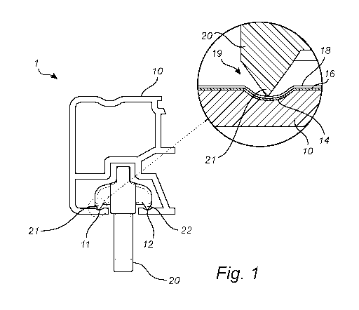
According to an embodiment there is thus provided a slide member, such as a
slide bar 10, having a slide surface 14 coated with a lacquer comprising a
resin 16. The
lacquer is in turn at least partly coated with a lipophilic composition
coating 18 to
provide a slide layer 19 with lowered friction. By coating the lacquer, the
sliding
friction is not just temporarily lowered, but long term low sliding friction
is obtained.
As already explained the lubricating coating may be permanent, dispensing with
the
need to replenish the lubricating coating. Further, very low amounts of the
lipophilic
composition are needed to provide lowered friction. Thus, contamination of the
lubricating coating does not pose any pronounced problem, as the coating, due
to the
very low amount present, does not have substantial adhesive properties. This
is in
contrast to the normal use of lubricants in plain bearings. Further, exposure
to
contaminations, e.g. dust etc., has been shown not to affect the lowered
friction. Neither
is the lubricating coating sensitive to washing. Wiping the slide member, e.g.
the slide
bar 10, with a dry and/or wet cloth, does not affect the lowered friction.
These
properties make the slide member, e.g. the slide bar 10, very useful for use
in systems
for sliding wardrobe doors, extendable tables, drawers of chests of drawers,
hanging
curtains, and similar applications.
CA 02997003 2018-02-28
WO 2017/044032 PCT/SE2016/050835
6
According to an embodiment the slide member is a slide bar 10 as depicted in
Figs. 1 to 3.
Such a low amount of the lipophilic composition coating 18 is needed, that the
lipophilic composition may be applied to a sliding member 20 rather than to
the slide
bar 10. In sliding over the slide bar 10, the lipophilic composition will be
transferred to
the slide bar 10 to provide a lipophilic composition coating 18. Hence, the
lipophilic
composition coating 18 could be applied to the slide bar 10, to the sliding
member 20,
or both.
According to the alternative embodiment depicted in Figs. 5a-c, the slide
member is a sliding part 110 whose slide layer, having a similar composition
as the
slide layer 19 described hereinbefore with reference to Fig. 1, is arranged to
slide along
the longitudinal axis of a linear slide profile 120, e.g. a plastic profile,
to form a linear
plain bearing. At least the slide surface (similar to the slide surface 14 of
Fig. 1) of the
sliding part 110 may, according to one embodiment, be an aluminum surface,
preferably
having an anodized oxide surface layer, onto which the lacquer is applied. The
thickness
of anodized oxide surface layer is preferably at least 5 micrometers, more
preferably at
least 10 micrometers. Further, the thickness of the anodized layer, if
present, may be
less than 250 micrometers, such as less than 100 micrometers or less than 50
micrometers. A sliding part according to such an alternative embodiment, an
example of
which is described in Figs. 5a-c, is less preferred for use in supporting
heavy sliding
doors. It is however considered to be well suited for use in sliding systems
for e.g.
extendable tables, drawers, etc.
While the slide member, e.g. a slide bar 10, preferably is an aluminum
member, e.g. a linear aluminum profile, with an aluminum oxide layer, also
other
materials coated with a lacquer comprising a resin may be considered. In order
to allow
for long term use and to carry loads, the slide member is typically made from
a hard
material, such as metal or glass. Especially the surface of the slide member
should
preferably be hard. The Vickers hardness of the material from which the slide
member
is made, may be at least 50 MPa, preferably at least 100 MPa, more preferably
at least
150 MPa, and most preferably at least 300 MPa. According to an embodiment, the
slide
member is a metal member, such as an aluminum member or a steel member. In
such
embodiment, the member is made of a metal. While it is preferred if an
aluminum
member has an oxide layer, also a raw, i.e. not oxidized, lacquered aluminum
member
may be used. It is however preferred if the surface of the aluminum member is
oxidized
to provide the aluminum member with a hard oxide surface layer.
CA 02997003 2018-02-28
WO 2017/044032 PCT/SE2016/050835
7
The slide member, e.g. a slide bar 10, may be an aluminum member. Further,
the surface of the aluminum member coated with the lacquer may be an aluminum
oxide
layer. The thickness of such oxide layer may be at least 5 micrometers, more
preferably
at least 10 micrometers. Further, the thickness of the oxide layer may be less
than 250
micrometers, such as less than 100 micrometers or less than 50 micrometers. As
known
in the art, the durability and hardness of the surface of aluminum profiles
may be
improved by oxidation due to the properties of aluminum oxide. The oxide layer
initially provided by anodically oxidation is porous. While the pores may be
closed by
steam treatment, sealing via anaphoretically coating with an acrylic resin
subsequently
heat cured to form the lacquer, is even more effective in sealing the porous
aluminum
oxide layer: This method, firstly disclosed by Honny Chemicals Co. Ltd. (cf.
GB
1,126,855), is often referred to as the Honny process.
Further, compared to plastic slide bars, a hard, stiff bar, such as aluminum
or
steel bar, may accept far more heavy loads and still provide low friction. The
present
slide bar 10 may thus also be used for sliding drawers.
In addition, it has been found that a relatively high contact pressure in the
contact between the slide bar 10 and the sliding member 20 reduces the
friction. For this
reason as well it is beneficial to make the slide bar 10 from a hard material,
such as
aluminum or steel, since such materials can accept higher contact pressures,
thereby
reducing friction.
According to an embodiment, the low friction slide bar 10 is a linear aluminum
profile. Preferably, the linear aluminum profile is oxidized (e.g. anodized)
in order to
increase the hardness of the surface. The profile is typically anaphoretically
coated with
an acrylic resin subsequently heat cured, thereby providing a linear slide bar
10 having a
lacquered slide surface 14. The aluminum profile may be anodized to obtain an
anodized layer thickness of at least 5 micrometers, more preferably at least
10
micrometers, prior to application of the resin of the lacquer. Further,
thickness of the
anodized layer may be less than 250 micrometers, such as less than 100
micrometers or
less than 50 micrometers. Such profiles may be obtained via the Honny process
(cf.
above) or one of its derivatives. Typically, the Honny process is used to
provide white,
glossy profiles. However, neither the Honny process nor the present
embodiments are
limited to white profiles. The preferable feature is that the lacquer is
suitable for being
coated with the lipophilic composition coating 18.
As known in the art, various resins, e.g. thermosetting resins, may be used to
lacquer aluminum bars and other bars, i.e. to form a lacquer on aluminum bars
and other
CA 02997003 2018-02-28
WO 2017/044032 PCT/SE2016/050835
8
bars. Further, thermosetting resins may also be used to lacquer other metal
members,
e.g. a sliding member made of steel. The lacquer comprises a resin. As known
to the
skilled person, a lacquer is a hard, thin coating. The resin of the lacquer
may for this
application preferably comprise polar groups, such as hydroxyl groups,
carboxylic acid
groups, amide groups, cyano groups (nitrile groups), halide groups, sulfide
groups,
carbamate group, aldehyd groups, and/or ketone groups. Further may the resin
of the
lacquer be a thermosetting resin.
Examples of resins for lacquering metal comprise acrylic resins and
polyurethane resins. According to an embodiment, the resin is an acrylic
resin, such as
an acrylate resin, an acrylamide resin, a methacrylate resin, or a methyl
metachrylate
resin, and mixtures thereof. According to another embodiment, the resin is a
polyurethane resin. The acrylic resin may be a thermosetting resin.
According to another embodiment, the resin of the lacquer is selected from the
group consisting of: acrylic resins, acrylate resins, acrylamide resins,
methacrylate
resins, methyl metachrylate resins, acrylonitrile resins, styrene-acrylonitril
resins,
acrylonitrile styrene acrylate resins, reaction products or a mechanical
mixture of alkyd
resin and water-soluble melamine resin, reaction products or a mechanical
mixture of a
vinyl-modified unsaturated alkyd resin and a water-soluble melamine resin, and
polymers and mixtures of one or several of these resins.
Further, the thermosetting resin may the reaction product or a mechanical
mixture of an alkyd resin and water-soluble melamine resin, or of a vinyl-
modified
unsaturated alkyd resin and a water-soluble melamine resin, the water-soluble
melamine
resin being obtained from hexamethylol melamine hexaalkylether. Vinyl modified
unsaturated alkyd resins may be made by polymerization of a vinyl monomer with
an
alkyd resin composed of an unsaturated oil or fatty acid. As known to the
skilled person,
the term "vinyl monomer" relates to a monomer having a vinyl group (-CH=CH2)
in the
molecule, such as an acrylic ester, for example methyl acrylate and ethyl
acrylate, a
methacrylic ester, for example methyl methacrylate and hydroxyethyl
methacrylate, an
unsaturated, organic acid, for example acrylic acid and methacrylic acid, and
styrene.
Processes for obtaining thermosetting acrylic resins are well-known to the
skilled person. As an example, they may be obtained by heating and stirring a
mixture
consisting of organic solvents, such as methanol, ethylene glycol, monobutyl
ether,
and/or cyclohexanone, unsaturated organic acids, such as acrylic acid,
methacrylic acid,
and/or maleic anhydride, a cross-linking vinyl monomer (as defined above),
such as
methylol-acrylamide and/or methylol methacrylamide, a polymerizable vinyl
monomer,
CA 02997003 2018-02-28
WO 2017/044032 PCT/SE2016/050835
9
such as styrene and/or acrylic acid ester, polymerization catalysts, such as
benzoyl
peroxides and/or lauroyl peroxides, and polymerization regulators, such as
dodecyl
mercaptan and/or carbon tetrachloride, to carry out polymerization, thereafter
neutralizing the product with, for example, an aqueous solution of ammonia
and/or
triethylamine to make the resin soluble in water. Further, as known to the
skilled person,
thermosetting resins composed of alkyd resins and water-soluble melamine resin
may
be obtained from hexamethylol melamine hexaalkyl ether, may be obtained by
mixing a
water-soluble melamine resin at a temperature of from room temperature to 100
C with
an alkyd resin modified with a fatty acid, the alkyd resin having an acid
value of from
10 to 80 and being obtained by heating a mixture consisting of (1) a saturated
or
unsaturated aliphatic acid, (2) ethylene glycol, glycerol, polyethylene
glycol, other
polyhydric alcohol or an epoxide, (3) adipic acid, sebacic acid, maleic
anhydride or
other polybasic acid or anhydride, and (4) a small quantity of cyclohexanone,
toluene or
other organic solvent. Thermosetting resins may also be obtained by mixing a
water-
soluble melamine resin and an alkyd resin from the ester exchange process, the
resin
being obtained by esterifying a mixture of dehydrated castor oil, an above-
mentioned
polyhydric alcohol and a small amount of an ester exchanging catalyst such as
caustic
potash, and thereafter esterifying also an above-mentioned polybasic acid or
anhydride.
As further known to the skilled person, thermosetting resins consisting of a
modified
acrylic resin and a water-soluble melamine resin, obtained from hexamethylol
melamine
hexaalkyl ether, may be obtained by polymerising by heating and stirring a
mixture
consisting of organic solvents, such as methanol, ethylene glycol, monobutyl
ether
and/or cyclohexanone, unsaturated acids, such as acrylic acid and/or
methacrylic acid, a
vinyl monomer (as hereinabove defined), such as styrene and/or acrylic acid
ester, a
cross-linking vinyl monomer, if necessary, such as methylol, is normally used.
Good
results may be obtained by using a concentration of resin of from 5 to 20% by
weight
and by regulating the voltage and the initial current density within a safe
and
economical range.
As known to the skilled person further resins for use in lacquering metal
surfaces are known in the art. As an example, the resin of the lacquer may be
selected
from the group consisting of cationic epoxy electrocoat, epoxy and polyester
resins, and
polyester resins. Still further, lacquers adapted for autodeposition coating,
such as
AutophoreticTm coatings (e.g. AquenceTM Autophoretic 866TM and BONDERITE
M-PP 930TM, the latter being an epoxy-acrylic urethane) available from Henkel
AG,
DE, may also be used in lacquering surfaces comprising iron.
CA 02997003 2018-02-28
WO 2017/044032 PCT/SE2016/050835
The slide surface 14 may be lacquered by electrocoating involving dipping the
slide member into a bath containing the lacquer and applying an electric field
to deposit
lacquer onto the slide member acting as one of the electrodes. Further, the
lacquer may
be provided in powder form or in liquid form. Both powder and liquid lacquers
may be
5 sprayed onto the slide surface 14 to coat it. For powder lacquers,
electro static coating
may be used. For liquid lacquers a wet spray application or application in a
bath may be
used. Further, liquid lacquers in a bath may apart from electrocoating be
applied by
autodeposition.
In order to provide low friction, the thickness of the lacquer should be as
even
10 as possible. Thus it may be preferred to apply the lacquer by an
electrocoating process,
e.g. anaphoretic coating (cf. the Honny method) or cataphoretic coating,
providing very
even coatings. There are two types of electrocoating, i.e. anodic and cathodic
electrocoating. Whereas the anodic process was the first to be developed
commercially,
the cathodic process is nowadays more widely used. In the anodic process, a
negatively
charged material is deposited on the positively charged component constituting
the
anode. In the cathodic process, positively charged material is deposited on
the
negatively charged component constituting the cathode. In the art, cathodic
electrocoating is also known as cathodic dip painting (CDP), cathodic dip
coating,
cataphoretic coating, cataphoresis and cathodic electrodeposition. Further,
the
electrocoating process may also be referred to by the trade names of the bath
material
used. Examples include Cathoguard (BASF), CorMax (Du Pont), Powercron (PPG)
and
Freiotherm (PPG). Further, also electrostatically coating by powder lacquers
or
autodepostion in a bath provide even coatings and may thus be used.
In lacquering steel surfaces, autodeposition may be used. As recognized by the
skilled person, one of the important steps in autodeposition is the coating
bath itself,
where water-based paint emulsion at low solids (usually around 4-8% by weight)
is
combined with two other products. A "starter" solution of acidified ferric
(Fe3+)
fluoride initiates the coating reaction and an oxidizing product stabilizes
the metal ions
in the solution. The coating emulsion is stable in the presence of ferric
ions, but unstable
in the presence of ferrous ions (Fe2+). Therefore, if ferrous ions are
liberated from the
metal substrate, localized paint deposition will occur on the surface.
Immersion of a
component made from ferrous metal (e.g. steel) into an autodeposition bath
causes the
acidic environment to liberate ferrous ions, thereby causing the coating
emulsion to be
deposited, forming a mono-layer of paint particles. Henkel Adhesive
Technologies
CA 02997003 2018-02-28
WO 2017/044032
PCT/SE2016/050835
11
(US)// Henkel AG & Co. KGaA (Germany) provides coatings under the trademark
BONDERITE for use in autodeposition.
As the lacquer coated on the slide member, e.g. the slide bar 10, typically is
more compressible than the material of the slide member, e.g. the slide bar
10, itself,
and as load carrying sliding members will apply pressure on the lacquer in
sliding over
the slide bar 10, the thickness of the lacquer preferably is to be kept thin
to reduce
compression of it. Compressing the lacquer may negatively affect the sliding
resistance;
especially at the start of the sliding sequence, i.e. when the sliding member
starts to
move along the slide bar 10 from a previous state of being at rest.
According to an embodiment, the thickness of the lacquer coated on the slide
member, e.g. the slide bar 10, is thus 100 i_tm or less, preferably 75 i_tm or
less, more
preferably 50 i_tm or less. Further, the thickness of the lacquer coated on
the slide
member, e.g. the slide bar 10, may be 5 to 75 1_1111, such as 10 to 50 1_1111,
or 15 to 40 1_1111.
Layers of these thicknesses have been found to provide for efficient sliding
behavior,
also at the instance when the sliding member starts to move along the slide
bar 10.
Not only the low dynamic friction provided by the present slide member, but
also the low difference between the static and dynamic friction provided by
the present
slide member is beneficial in terms of the sliding behavior.
In order to reduce the friction of the slide member, e.g. the slide bar 10,
the
slide member, e.g. the slide bar 10, is, at least partly, coated with a
lipophilic
composition coating 18 to provide a slide layer 19. Further, while various
components
may be present in the lipophilic composition coating 18 present on the
lacquer, the
composition typically comprises components with intermediate to long carbon
chains,
e.g. carbon chains having a carbon atom length of C6 or more, such as C8 or
more.
Thus, the lipophilic composition coating 18 may comprise compounds comprising
C6 to
C40, such as C8 to C30 or even C10 to C24, non-aromatic hydrocarbyl groups.
Typical
examples of such non-aromatic hydrocarbyl groups are alkenyl groups and alkyl
groups,
e.g. alkyl groups. Examples of compounds comprising such non-aromatic
hydrocarbyl
groups are:
- C6 to C40 non-aromatic hydrocarbons, such as alkenes and/or alkanes, e.g.
alkanes;
- tri-glycerides, e.g. triglycerides comprising C6 to C40, such as C8 to
C30,non-aromatic hydrocarbyl groups; and
- fatty acids, e.g. C6 to C40, such as C8 to C30, carboxylic acids, and
esters
thereof, such as alkyl esters of fatty acids, e.g. methyl esters.
CA 02997003 2018-02-28
WO 2017/044032 PCT/SE2016/050835
12
As known to the skilled person and as recognized in IUPAC's gold book
(International Union of Pure and Applied Chemistry, Compendium of Chemical
Terminology - Gold Book, Version 2.3.3 of 2014-02-24):
- hydrocarbon denotes compounds consisting of carbon and hydrogen only;
- hydrocarbyl denotes univalent groups formed by removing a hydrogen atom
from a hydrocarbon;
- alkane denotes acyclic branched or unbranched hydrocarbons having the
general formula CnH2n+2;
- alkene denotes acyclic branched or unbranched hydrocarbons having one or
more carbon¨carbon double bond(s);
- alkyl denotes a univalent group derived from alkanes by removal of a
hydrogen atom from any carbon atom ¨Cal2n+1;
- alkenyl denotes an univalent group derived from alkenes by removal of a
hydrogen atom from any carbon atom;
- fatty acid denotes an aliphatic monocarboxylic acid;
- triglyceride denotes an ester of glycerol (propane-1,2,3-triol) with
three fatty
acids (tri-O-acylglycerol); and
- non-aromatic denotes a compound not comprising any cyclically conjugated
molecular entity with increased stability due to delocalization.
According to an embodiment, the lipophilic composition coating 18 present on
the lacquer comprises at least 1 wt.% such as at least 5 wt.%, 10 wt.%, 25
wt.%, 50
wt.%, 60 wt.%, 70 wt.%, 75 wt.%, 80 wt.%, 85 wt.% or at least 90 wt.% of
compounds
comprising C6 to C40, such as C8 to C30, alkyl groups. Thus, the lipophilic
composition coating 18 may comprise least 1 wt.% such as at least 5 wt.%, 10
wt.%, 25
wt.%, 50 wt.%, 60 wt.%, 70 wt.%, 75 wt.%, 80 wt.%, 85 wt.% or at least 90 wt.%
C6
to C40, such as C8 to C30, alkenes and/or alkanes, e.g. alkanes. Further, the
lipophilic
composition coating 18 present on the lacquer may comprise least 1 wt.% such
as at
least 5 wt.%, 10 wt.%, 25 wt.%, 50 wt.%, 60 wt.%, 70 wt.%, 75 wt.%, 80 wt.%,
85
wt.% or at least 90 wt.% triglycerides and/or fatty acids (or alkyl esters
thereof).
Whereas fatty acids have been found to improve the lubricating effect of
mixtures of alkanes, such as liquid paraffin, they are less effective if used
on their own.
It is thus preferred if the lipophilic composition present on the lacquer is
not only
composed of fatty acids. The lipophilic composition present on the lacquer may
thus
comprise less than 99 wt.% fatty acids, such as less than 95 wt.% fatty acids.
However,
lipophilic compositions essentially only comprising triglycerides, such as
coco nut oil,
CA 02997003 2018-02-28
WO 2017/044032 PCT/SE2016/050835
13
provide very low friction and do thus represent a preferred lipophilic
composition
present on the lacquer.
According to an embodiment, the lipophilic composition coating 18 present on
the lacquer comprises at least 1 wt.% such as at least 5 wt.%, 10 wt.%, 25
wt.%, 50
wt.%, 60 wt.%, 70 wt.%, 75 wt.%, 80 wt.%, 85 wt.% or at least 90 wt.% of
alkenes
and/or alkanes, e.g. alkanes and 0.1 to 50 wt.%, such as 1 to 40 wt.% or 5 to
30 wt.%
triglycerides and/or fatty acids
According to another embodiment, the lipophilic composition coating 18
present on the lacquer comprises at least 1 wt.% such as at least 5 wt.%, 10
wt.%, 25
wt.%, 50 wt.%, 60 wt.%, 75 wt.%, 80 wt.% or at least 90 wt.% in total of
triglycerides
and/or fatty acids and 0.1 to 95 wt.%, such as 1 to 90 wt.% or 5 to 60 wt.%
alkenes
and/or alkanes, e.g. alkanes.
As already mentioned, typical examples of compounds comprising C6 to C40
non-aromatic hydrocarbyl groups are tri-glycerides and fatty acids. According
to an
embodiment, the lipophilic composition coating 18 present on the lacquer
comprises
triglycerides and/or fatty acids. The lipophilic composition coating 18 may
thus
comprise more than 25 wt.%, e.g. more than 50 wt.%, such as 50 to 100 wt.%, or
75 to
95 wt.%, in total of triglycerides and fatty acids. The triglycerides and/or
fatty acids
may either be used as the major component in the lipophilic composition
coating 18 or
as additives.
If to be used as a major component, the lipophilic composition present on the
lacquer coating may comprise more than 50 wt.%, such as 50 to 100 wt.%, or 75
to 95
wt.%, triglycerides, e.g. triglycerides to at least 90 %.wt composed of a
glycerol residue
and 3 residues of caproic acid, caprylic acid, capric acid, lauric acid,
myristic acid,
palmitic acid, stearic acid, and/or arachidic acid, such as 3 residues of
lauric acid,
myristic acid, palmitic acid, and/or stearic acid. According to an embodiment,
the
lipophilic composition coating 18 present on the lacquer comprises coconut
oil, such as
at least 25 wt.% such as at least 50 wt.%, 60 wt.%, 70 wt.%, 75 wt.%, 80 wt.%,
85 wt.%
or at least 90 wt.% coconut oil. Coconut oil comprises triglycerides composed
of fatty
acids that are to a high degree saturated fatty acids. The coconut oil may be
hydrogenated to various degrees to further reduce the amount of unsaturated
fatty acids
residues. Further, the lipophilic composition coating 18 present on the
lacquer may
comprise more than 50 wt.%, such as 50 to 100 wt.%, or 75 to 95 wt.% fatty
acids, e.g.
caproic acid, caprylic acid, capric acid, lauric acid, myristic acid, palmitic
acid, stearic
acid, and/or arachidic acid, such as lauric acid, myristic acid, palmitic
acid, and/or
CA 02997003 2018-02-28
WO 2017/044032 PCT/SE2016/050835
14
stearic acid. Furthermore, the lipophilic composition coating 18 present on
the lacquer
may comprise more than 50 wt.%, such as 50 to 100 wt.%, or 75 to 95 wt.% alkyl
esters
of fatty acids, e.g. methyl or ethyl esters. The esterfied fatty acids may be
caproic acid,
caprylic acid, capric acid, lauric acid, myristic acid, palmitic acid, stearic
acid, and/or
arachidic acid, such as lauric acid, myristic acid, palmitic acid, and/or
stearic acid.
If to be used as an additive, the lipophilic composition coating 18 present on
the lacquer may comprise 0.1 to 50 wt.%, such as 1 to 30 wt.% or 5 to 15 wt.%,
triglycerides, e.g. triglycerides to at least 90% composed of a glycerol
residue and 3
residues of caproic acid, caprylic acid, capric acid, lauric acid, myristic
acid, palmitic
acid, stearic acid, and/or arachidic acid, such as 3 residues of lauric acid,
myristic acid,
palmitic acid, and/or stearic acid. A preferred example of composition to be
used to
provide a lipophilic composition coating 18 comprising triglycerides is
coconut oil.
According to an embodiment, the lipophilic composition coating 18 present on
the
lacquer comprises coconut oil, such as 0.1 to 50 wt.%, such as 1 to 30 wt.% or
5 to 15
wt.%, coconut oil. According to an embodiment, the lipophilic composition
coating 18
present on the lacquer comprises at least 50 wt.% coconut oil, such as at
least 60 wt.%,
70 wt.%, 75 wt.%, 80 wt.%, 85 wt.%, or at least 90 wt.% coconut oil. Coconut
oil
comprises triglycerides composed of fatty acids that are to a high degree
saturated fatty
acids. The coconut oil may be hydrogenated to various degrees to further
reduce the
amount of unsaturated fatty acids residues. Further, the lipophilic
composition present
on the lacquer may comprise 0.1 to 50 wt.%, such as 1 to 30 wt.% or 5 to 15
wt.%, of
fatty acids, e.g. caproic acid, caprylic acid, capric acid, lauric acid,
myristic acid,
palmitic acid, stearic acid, and/or arachidic acid, such as lauric acid,
myristic acid,
palmitic acid, and/or stearic acid. Furthermore, the lipophilic composition
coating 18
present on the lacquer may comprise 0.1 to 50 wt.%, such as 1 to 30 wt.% or 5
to 15
wt.%, of alkyl esters of fatty acids, e.g. methyl or ethyl esters. The
esterified fatty acids
may be caproic acid, caprylic acid, capric acid, lauric acid, myristic acid,
palmitic acid,
stearic acid, and/or arachidic acid, such as lauric acid, myristic acid,
palmitic acid,
and/or stearic acid.
Both saturated and un-saturated compounds comprising C6 to C40 non-
aromatic hydrocarbyl groups are well-known in the art. While both types of
compounds
will be efficient in reducing the sliding resistance, saturated compounds
comprising C6
to C40 non-aromatic hydrocarbyl groups are deemed to be less sensitive to
oxidative
degradation. Thus, it may be preferred to use compounds comprising C6 to C40
non-
aromatic hydrocarbyl groups being triglycerides composed of saturated fatty
acids
CA 02997003 2018-02-28
WO 2017/044032 PCT/SE2016/050835
residues and/or saturated fatty acids in the composition. It may however not
be
necessary to use a 100% saturated fatty acids and/or triglycerides. As
example, coconut
oil is envisaged to have sufficient long term stability, though saturated
fatty acids and/or
triglycerides are preferred in terms of their long term stability.
5 As mentioned, the lipophilic composition coating 18 present on the
lacquer
may comprises at least 1 wt.% C6 to C40 alkanes. As an example, the lipophilic
composition coating 18 present on the lacquer may thus comprise mineral oil,
such as at
least 1 wt.%, such as at least 5 wt.%, 10 wt.%, 25 wt.%, 50 wt.%, 60 wt.%, 70
wt.%, 75
wt.%, 80 wt.%, 85 wt.%, or at least 90 wt.% mineral oil. Mineral oil is a
colorless,
10 odorless, light mixture of higher alkanes from a non-vegetable (mineral)
source.
Further, the lipophilic composition present on the lacquer coating may
comprise liquid
paraffin, such as at least 1 wt.%, such as at least 5 wt.%, 10 wt.%, 25 wt.%,
50 wt.%, 60
wt.%, 70 wt.%, 75 wt.%, 80 wt.%, 85 wt.%, or at least 90 wt.% liquid paraffin.
Liquid
paraffin, also known as paraffinum liquidum, is a very highly refined mineral
oil used in
15 cosmetics and for medical purposes. A preferred form is the one having
CAS number
8012-95-1. Furthermore, the lipophilic composition coating 18 present on the
lacquer
may comprise petroleum jelly (also known as petrolatum, white petrolatum, soft
paraffin or multi-hydrocarbon), such as at least 1 wt.%, such as at least 5
wt.%, 10
wt.%, 25 wt.%, 50 wt.%, 60 wt.%, 70 wt.%, 75 wt.%, 80 wt.%, 85 wt.%, or at
least 90
wt.% petroleum jelly. Petroleum jelly is a semi-solid mixture of hydrocarbons
(with
carbon numbers mainly higher than 25). A preferred form is the one having CAS
number 8009-03-8.
A further embodiment (cf. Figs. 1 and 3) of the invention relates to sliding
system 1, comprising the disclosed slide bar 10 and at least one sliding
member 20. The
slide bar 10 is typically linear, such as linear aluminium profile. By
arranging the
interface between slide layer 19 of the slide bar 10 and the sliding member 20
in sliding
contact a linear plain bearing is provided.The sliding member 20 is arranged
to allow
for linear movement of the sliding member in sliding over the slide layer 19
along the
longitudinal axis of the linear slide bar 10. Further, the slide bar 10 may be
provided
with a track, which in this embodiment has the form of a groove 11 extending
along the
longitudinal axis off the slide bar 1 and defining a slide direction along the
longitudinal
axis of the slide bar 10. When the slide bar 10 is provided with a groove 11,
the slide
layer 19 is present at least in the groove 11.
The track, which may for example have the form of a groove, an example of
such a groove 11 is illustrated in Fig. 1, or the form of a ridge, improves
the control of
CA 02997003 2018-02-28
WO 2017/044032 PCT/SE2016/050835
16
the lateral position of the sliding member 20 in relation to the slide bar 10
when the
sliding member 20 slides along the slide bar 10.
An enlarged detail in Fig. 1 illustrates how the slide member 10, which is
made
from, in this embodiment, aluminum, has a slide surface 14. The slide surface
14 is
coated with the lacquer comprising a resin 16. The lacquer comprising a resin
16 is in
turn coated with a lipophilic composition coating 18. Thereby a slide layer 19
is formed.
The sliding member 20 may slide over this slide layer 19 at a very low
friction.
Further, as shown in Figs. 2 and 4, the part of the sliding member 20 arranged
in contact with the slide layer 19 may be configured as a blade 21 extending
in the
sliding direction. It was surprisingly found that decreasing the contact area
at the
interface between the slide bar 10 and the sliding member 20 reduced the
friction.
Normally the risk for the bearing seizing typically increases with reduced
contact area.
In order to provide the sliding system 1, the sliding member 20 comprises at
least one
contact point in contact with the slide bar 10 at the interface between the
slide bar 10
and the sliding member 20. According to an embodiment, the contact area of
each
individual contact point is less than 3 mm2, such as less than 1.5 mm2, or
less than 0.75
mm2. The slide member may further be provided with more than one contact
point, such
as 2, 3, or 4 contact points. If, for example, the sliding member is provided
with a blade
21 extending in the sliding direction, then the edge of the blade 21
represents an
individual contact point.
It has been found that the friction becomes lower when the contact pressure
between the sliding member and the slide bar is relatively high. The contact
pressure is
calculated by dividing the load carried by each individual contact point by
the contact
area of the contact point. For example, if the sliding door has a total weight
of 8.5 kg
this represents a total load of 83.3 N. The sliding door may carried by two
sliding
members 20 of the design illustrated in Fig. 2. Each sliding member 20 having
four
contact points, i.e. edges of the blades 21, 22, 23 in Fig. 2, each such
contact point
having an area of 0.675 mm2. The contact pressure is then: 83.3 N / (2x4x0.675
mm2) =
15.4 N/mm2. Preferably, the contact pressure in said at least one contact
point is at least
4 N/mm2, more preferably at least 8 N/mm2, such as at least 12 N/mm2.
Preferably, the
contact pressure is lower than the strain at yield (= yield strength) for the
material from
which the sliding member 20 is made.
In order to provide low friction, at least the part of the sliding member 20
in
contact with the slide layer 19 is preferably made of a plastic comprising a
polymer,
such as a polymer comprising polar groups. Examples of such polar groups
include
CA 02997003 2018-02-28
WO 2017/044032 PCT/SE2016/050835
17
hydroxyl groups, carboxylic acid groups, amide groups, halide groups, sulfide
groups,
cyano groups (nitrile groups), carbamate groups, aldehyde groups, and/or
ketone groups
The polymer may be selected from the group consisting of polyoxymethylenes
(POM), polyesters (e.g. thermoplastic polyesters, such as polyethylene
terephthalate
(PET), polytrimethylene terephthalate (PTT), polybutylene terephthalate (PBT),
and
polylactic acid (PLA), as well as bio-based thermoplastic polyesters, such as
polyhydroxyalkanoates (PHA), polyhydroxybutyrate (PHB), and polyethylene
furanoate
(PEF)), polyamides (PA), polyvinyl chloride (PVC), polyphenylene sulfide
(PPS),
polyaryletherketone (PAEK; e.g. Polyether ether ketone (PEEK)), and
Polytetrafluoroethylene (PTFE). Further, not only the part of the sliding
member 20 in
contact with the slide layer 19 may be made of a polymer, but the entire
sliding member
20. Thus, sliding member may be made from a plastic comprising a polymer. As
recognized by the skilled person, the plastic may further comprise other
additives, such
as fillers, colorants, and/or plasticizers. Further, the sliding member 20 may
be made
from a composite comprising a polymer, such as one of the above listed
polymers, filled
with particles and/or fibers. The particles and/or fibers will increase the
hardness, the
stiffness, the creep resistance and elongation (compression) at yield of the
sliding
member 20. While not affecting the friction, presence of particles and/or
fibers may
affect the wear. Thus, use of particles and/or fibers in the plastic is less
preferred.
According to an embodiment (cf. Fig. 2) the sliding member 20 may be
provided with two parallel, displaced blades 21, 22 in order to prevent
rotation along the
sliding axis. Further, the slide bar 10 may be provided with two parallel
grooves 11, 12
arranged along each side of its longitudinal sliding axis. Parallel grooves
11, 12 will
support and guide such two parallel blades 21, 22 of the sliding member (cf.
Fig. 1).
Further, slide bars with two parallel grooves 11, 11, supporting two separate
slide
members 20, are preferred in sliding systems arranged to support more than one
sliding
door (cf. Fig. 3) as only one slide bar is then required. Furthermore, the
sliding member
20 may be provided with two, or more, parallel blades 21, 23 (cf. Fig. 2 and
4) arranged
along the same longitudinal axis. The sliding member 20 may be provided with
two
parallel blades 21, 23 adapted for running in the same groove 11 independently
of the
presence, or non-presence, of parallel, displaced blades 21, 22 adapted for
running in
two parallel grooves 11, 12.
The sliding system 1 may be used to support a sliding door 30 connected to the
sliding member 20. Thus, the sliding member 20 may be provided with fastening
CA 02997003 2018-02-28
WO 2017/044032 PCT/SE2016/050835
18
arrangements 28, e.g. holes, pins, etc., for connecting the sliding member 20
to the
sliding door 30.
A further embodiment (cf. Fig 5) of the invention relates to alternative
sliding
system 1, comprising a linear slide profile 120 and a slide member, the slide
member
being a sliding part 110 arranged to slide along the longitudinal axis of a
linear slide
profile 120 to form a linear plain bearing. The interface between the slide
layer (similar
to the slide layer 19 illustrated in Fig. 1) of the sliding part 110 and the
linear slide
profile forms a linear plain bearing to allow for linear movement of the
sliding part 110
sliding along the longitudinal axis of the linear slide profile 120. According
to such an
embodiment, the linear slide profile 120 may be a plastic profile provided
with at least
one ridge 121a-e extending along the longitudinal axis of the profile. The
plastic profile
may be provided with a sliding channel 125 for the sliding part 110 to slide
in. At least
one surface of the channel 125 may be provided with a ridge 121a-e extending
along the
longitudinal axis of the channel 125. As an example, the plastic profile 120
may be U-
shaped with at least one of its interior surfaces provided with a ridge
extending along
the longitudinal axis of the slide bar. The plastic profile 120 may be fitted
inside a
support member 150, such as a metal rod, to enhance the mechanical strength of
the
plastic profile. Further, also other surfaces of the channel 125 may be
provided with
ridge(s) 121a-e extending along the longitudinal axis of the channel. More
than one
interior side of a U-shaped plastic profile may be provided with a ridge(s)
121a-e
extending along the longitudinal axis of the profile 120. The sliding system
is arranged
in manner such that the slide layer 19 of the sliding part 110 engages with
the ridge(s)
121a-e in sliding over the linear slide profile 120. Part of the sliding part
110 may be
arranged to fit into the sliding channel 125 and to engage with the ridge(s)
121a-e in
sliding within the channel (cf. Fig. Sc). This part may have a cross-section
corresponding, in general shape, not size, to the cross-section of the channel
excluding
the ridge(s) 121a-e. The plastic profile and its ridge(s) 121a-e may then
serve to guide
the sliding part 110.
As already mentioned, it was surprisingly found that decreasing the contact
area at the interface between the two parts of the linear bearing reduces the
friction.
Normally one would expect the friction to increase with reduced contact area.
Further,
the risk for the bearing seizing typically increases with reduced contact
area. In order to
provide the sliding system, the linear slide profile 120 comprises at least
one contact
point in contact with the sliding part 110 at the interface between the linear
slide profile
120 and the sliding part 110. According to an embodiment, the contact area of
each
CA 02997003 2018-02-28
WO 2017/044032 PCT/SE2016/050835
19
individual contact point is less than 3 mm2, such as less than 1.5 mm2, or
less than 0.75
mm2. The linear slide profile 120 may further be provided with more than one
contact
point, such as 2, 3, or 4 contact points. If the linear slide profile is
provided with a ridge
121a-e extending in the sliding direction, its edge, or rather that part of
the edge which
is at a certain instance in contact with the sliding part, represents the
contact point.
It has been found that the friction becomes lower when the contact pressure
between the sliding part 110 and the linear slide profile bar 120 is
relatively high. The
contact pressure is calculated by dividing the load carried by each individual
contact
point by the contact area of the contact point. Preferably, the contact
pressure in said at
least one contact point is at least 4 N/mm2, more preferably at least 8 N/mm2,
such as at
least 12 N/mm2. Preferably, the contact pressure is lower than the strain at
yield (= yield
strength) for the material from which the linear slide profile 120 is made.
In order to provide low friction, at least the part of the linear slide
profile 120
in contact with the slide layer 19 of the sliding part 110 is preferably made
of a plastic
comprising a polymer, such as a polymer comprising polar groups. Examples of
such
polar groups include hydroxyl groups, carboxylic acid groups, amide groups,
halide
groups, sulfide groups, cyano groups (nitrile groups), carbamate groups,
aldehyde
groups, and/or ketone groups
The polymer may be selected from the group consisting of polyoxymethylenes
(POM), polyesters (e.g. thermoplastic polyesters, such as polyethylene
terephthalate
(PET), polytrimethylene terephthalate (PTT), polybutylene terephthalate (PBT),
and
polylactic acid (PLA), as well as bio-based thermoplastic polyesters, such as
polyhydroxyalkanoates (PHA), polyhydroxybutyrate (PHB), and polyethylene
furanoate
(PEF)), polyamides (PA), polyvinyl chloride (PVC), polyphenylene sulfide
(PPS),
polyaryletherketone (PAEK; e.g. Polyether ether ketone (PEEK)), and
Polytetrafluoroethylene (PTFE). According to one embodiment not only the part
of the
linear slide profile 120 in contact with the slide layer 19 is made of a
polymer, but the
entire linear slide profile 120 is made of a polymer. Thus, linear slide
profile 120 may in
its entirety be made from a plastic comprising a polymer. As recognized by the
skilled
person, the plastic may further comprise other additives, such fillers,
colorants, and/or
plasticizers. Further, the linear slide profile 120 may made from a composite
comprising
a polymer, such as one of the above listed polymers, filled with particles
and/or fibers.
The particles and/or fibers will increase the hardness, the stiffness, the
creep resistance
and elongation (compression) at yield of the linear slide profile. While not
affecting the
friction, presence of particles and/or fibers may still affect the wear. Thus,
use of
CA 02997003 2018-02-28
WO 2017/044032 PCT/SE2016/050835
particles and/or fibers in the plastic is less preferred.A further embodiment
of the
invention relates to a sliding door arrangement 2, schematically depicted in
Fig. 6, such
as a sliding door arrangement for a wardrobe. Such an arrangement 2 comprises
the
disclosed sliding system 1 and a sliding door 30. One, or often two or three,
sliding
5 member/-s 20 is/are arranged to support the sliding door 30 to allow for
linear
movement of the sliding door 30 along the longitudinal axis of the linear
slide bar 10.
Typically the sliding door 30 is connected to the sliding member 20 supporting
the door.
The slide bar 10 may be horizontally arranged in use with the slide layer 19
facing
upwards to support the sliding member 20. As the sliding member 20 may be
arranged
10 to horizontally slide over the slide bar 10, the sliding door 30 may be
moved along the
horizontal axis of the linear slide bar 1. The sliding door, such as a sliding
door 30 for a
wardrobe, will typically be arranged hanging from the linear slide bar 10.
A sliding door 30 may however also be mounted standing on the linear slide
bar 10. Smaller doors, such as kitchen cabinet doors, are examples of doors
which may
15 be standing on the linear slide bar 10. Further, sliding doors 30
mounted standing on the
linear slide bar 10, may not necessarily extend in the vertical plane, but may
be slightly
tilted with respect to the vertical plane, as is known for kitchen cabinet
doors. However,
given the low friction provided by the present sliding system, also larger
doors may be
mounted standing on the linear slide bar 10.
20 Furthermore there is, according to an embodiment, provided a method
for
providing slide member. In such a method there is provided a member having a
slide
surface 14 coated with a lacquer comprising a resin 16. In order to provide
the member
with lowered friction, the lacquer is, at least partly, coated with a
lipophilic composition
coating 18. Aspects of the member, the lacquer, and the lipophilic composition
coating
18 have been provided herein above and are applicable to this embodiment as
well. In
applying the lipophilic composition to provide the lipophilic composition
coating 18,
the lipophilic composition may firstly be heated, such as melted, to reduce
its viscosity.
Further, the lipophilic composition may be dissolved in a solvent to
facilitate
application. Lipophilic composition being in a liquid state at room
temperature may also
be applied directly. After application, any such solvent may be evaporated, at
least
partly. The lipophilic composition to provide the lipophilic composition
coating 18 may
be applied in various ways, such as by spraying, smearing, painting, coating,
spreading
etc.
According to an embodiment, the lipophilic composition is applied by the end-
consumer. Thus, the slide member, the sliding system or arrangements
comprising the
CA 02997003 2018-02-28
WO 2017/044032 PCT/SE2016/050835
21
slide member may be provided together with a lipophilic composition to be
applied by
the end-consumer, i.e. the lacquer is un-coated upon delivery.
Similarly, another embodiment relates to the use of such a lipophilic
composition as an irreversibly bound lubricant for a slide surface 14 of a
slide member.
By "irreversibly bound lubricant" is, according to an embodiment, meant that
the
lubricant is not removed from the slide surface 14 during normal operation of
the
sliding system and that it cannot be easily removed using mechanical means,
e.g. it
cannot be removed by wiping the slide surface 14 with a cloth. As described
herein, the
slide surface of the slide member is coated with a lacquer comprising a resin
16.
Aspects of the member, the lacquer, and the lipophilic composition coating 18
have
been provided herein above and are applicable to this embodiment as well.
As described previously a sliding system according to the principles set forth
in
this specification may also be used for extendable beds, extendable bed
frames, sofa
beds, drawers, tables, etc. An embodiment of an extendable bed/bed frame
sliding
system 1001 for an extendable bed or bed frame is shown in Figs. 9a-12,
whereby the
individual parts are disclosed in detail. The sliding system 1001 allows for a
full
extension of a moving part of an extendable bed or extendable bed frame,
meaning that
the moveable part may be drawn out from a fixed frame structure. The moveable
part
may e.g. be a foot end of the extendable bed or extendable bed frame, while
the fixed
frame structure may be the head end.
The sliding system 1001 comprises a first guiding rail 1100, which is best
shown in Figs. 9a-9b, comprising securing means 1120, here in the form of two
spaced
apart through holes, for securely attaching the first guiding rail 1100 to the
inner wall of
a fixed frame structure, such as to the head end of the extendable bed or bed
frame.
Horizontal mounting of the first guiding rail 1100 is preferred. The first
guiding rail
1100 has a C-shape, better shown in Fig. 9b, and is provided with two or more
sets of
sliding members 1200 that are all mounted inside the C-shape of the guiding
rail 1100.
Two sliding members 1200 are fixedly mounted to the upper part of the C-shape,
and
two sliding members 1200 are fixedly mounted to the bottom part of the C-
shape. The
sliding members 1200 are arranged in pairs, such that an upper sliding member
1200
and a lower sliding member 1200 are aligned in a vertical direction. The
sliding
members 1200 are thus stationary relative the fixed frame structure when the
first
guiding rail 1100 is mounted to the fixed frame structure. The sliding members
1200
may be made of polymer materials according to the principles described
hereinbefore.
CA 02997003 2018-02-28
WO 2017/044032 PCT/SE2016/050835
22
Now turning to Figs. 10a-b the sliding system 1001 also comprises a slide
member which in this embodiment is an intermediate guiding rail in the form of
an
intermediate slide bar 1300. The intermediate slide bar 1300 is configured as
a C-shape
and has an upper and outer slide surface 1320, an upper and inner slide
surface 1340, a
bottom and inner slide surface 1360, and a bottom and outer slide surface
1380, as best
shown in Fig. 10b. These slide surfaces 1320, 1340, 1360, 1380 are preferably
planar,
and the width of the outer slide surfaces 1320, 1380 is dimensioned to engage
with the
sliding members 1200 of the first guiding rail 1100. The slide surfaces 1320,
1230,
1360, 1380 may be formed according to the principles described hereinbefore,
similar to
the slide surface 14, and are provided with a lacquer comprising a resin and a
lipophilic
composition coating to form respective slide layers which may be similar to
the slide
layer 19 described hereinbefore, see for example Fig. 1 and the related
description.
The intermediate slide bar 1300 is thus configured to be received by the C-
shaped first guiding rail 1100.
The sliding system 1001 also comprises a second guiding rail 1400 to be
fixedly mounted to a moveable part, e.g. the foot end, of the extendable bed
or
extendable bed frame. The second guiding rail 1400 is provided with means (not
shown), such as screw holes or similar, for attaching the second guiding rail
1400 to the
moveable part. As can be seen in Figs. ha-b the second guiding rail 1400 is L-
shaped,
whereby the lower part 1420 can be used for aligning with the bottom end of
the
moveable part. Hence the moveable part of the extendable bed or bed frame may
rest on
the lower part 1420, while the side wall of the moveable part is screwed to
the vertical
part 1440 of the second guiding rail 1400.
The second guiding rail 1400 is provided with one or more sliding members
1500 protruding outwards for engagement with the inner slide surfaces 1340,
1360 of
the intermediate slide bar 1300. In this embodiment there are two separate
sliding
members 1500 attached to the vertical part 1440 of each second guiding rail
1400. The
vertical height of the sliding members 1500 thus corresponds to the distance
between
the two inner slide surfaces 1340, 1360 of the intermediate slide bar 1300.
The sliding
members 1500 may be made of polymer materials according to the principles
described
hereinbefore.
Fig. 12 illustrates a cross-sectional view of the sliding system 1001 in an
assembled state. Two sliding interfaces are thus provided, the first one being
realized by
the sliding engagement between the sliding members 1200 of the first guiding
rail 1100
and the outer slide surfaces 1320, 1380 of the intermediate slide bar 1300.
The second
CA 02997003 2018-02-28
WO 2017/044032 PCT/SE2016/050835
23
sliding interface is realized by the sliding engagement between the inner
slide surfaces
1340, 1360 of the intermediate slide bar 1300 and the sliding members 1500 of
the
second guiding rail 1400. The sliding interfaces may include protrusions,
e.g., blades,
and grooves according to principles described hereinabove, see for example
Fig. 1.
While the embodiment of Figs. 9a to 12 is described as an extendable bed
and/or extendable bed frame sliding system 1001 for an extendable bed or
extendable
bed frame it will be appreciated that the slide member and the sliding system
1001
according to the described principles may be useful also in other
applications, in
particular applications where a moveable part is to be drawn out from a fixed
part,
including e.g. extendable tables, drawers to be drawn out of chests of
drawers, etc.
Without further elaboration, it is believed that one skilled in the art may,
using
the preceding description, utilize the present invention to its fullest
extent. The
preceding preferred specific embodiments are, therefore, to be construed as
merely
illustrative and not limitative of the disclosure in any way whatsoever.
Although the present invention has been described above with reference to
specific embodiments, it is not intended to be limited to the specific form
set forth
herein. Rather, the invention is limited only by the accompanying claims and
other
embodiments than those specifically described above are equally possible
within the
scope of these appended claims, e.g. different embodiments than those
described above.
In the claims, the term "comprises/comprising" does not exclude the presence
of other elements or steps. Additionally, although individual features may be
included
in different claims, these may possibly advantageously be combined, and the
inclusion
of two features in different claims does not imply that a combination of those
features is
not feasible and/or advantageous.
In addition, singular references do not exclude a plurality. The terms "a",
"an",
"first", "second" etc. do not preclude a plurality.
Examples
The following examples are mere examples and should by no means be
interpreted to limit the scope of the invention, as the invention is limited
only by the
accompanying claims.
General
All chemicals were obtained from Sigma-Aldrich. In providing mixtures, e.g.
palmitic acid 10 mass% in liquid paraffin, the two compounds (e.g. 3 g
palmitic acid
CA 02997003 2018-02-28
WO 2017/044032 PCT/SE2016/050835
24
and 27 g liquid paraffin) were mixed under heating to melt the mixture.
Further, the
mixtures were applied to the slide bar before solidifying.
The test procedure used was based on SS-EN 14882:205. In short, a sled with
parallel plastic blades (four in total; two along each longitudinal slide
axis) of POM was
positioned on an anodized aluminum profile (cf. Fig. 7) having been
anaphoretically
coated with an acrylic resin and subsequently heat cured to provide a
lacquered slide
surface. Aluminum profiles lacquered in this way are for example provided by
Sapa
Profiler AB, 574 38 Vetlanda, Sweden, and are marketed under the trade name
SAPA
HM-white, the materials being produced using the Sapa HM-white method which is
based on the above referenced Honny method. In the friction measurements, the
sled
was pulled over the slide bar at a constant speed of 500 mm/min and the force
necessary
to pull the sled was registered using an Instron 5966 tension testing system
(cf. Fig. 8).
The total weight of the sled corresponds to 10 N. Fresh profiles were used for
each
lipophilic composition, as the lipophilic compositions cannot be removed once
applied.
However, the profiles were re-used after the control experiments (no
lipophilic
compositions applied), washing and ageing, respectively.
Example 1
By using the test procedure described above, the resulting friction from
application of various lipophilic compositions to anodized, lacquered aluminum
profiles
was determined. The resulting dynamic friction, mean value from three test
sequences,
was registered and compared to the dynamic friction for anodized aluminum
profiles
provided with a lacquer but not coated with any lipophilic composition (=
control). The
results are provided in Table 1 and 2 below.
Table 1 ¨ Fatty acids in liquid paraffin
Lipophilic composition Wash Ageing Dynamic friction Mean (n=3)
No (control) 0.214
MA5% 0.049
MA10% 3 days 0.046
MA30% 0.049
MA10% Yes 0.041
PA10% 3 days 0.047
PA10% Yes 0.042
SA10% 3 days 0.050
CA 02997003 2018-02-28
WO 2017/044032
PCT/SE2016/050835
SA10% Yes 0.044
LP 0.053
LP Yes 0.050
MA5%/10%/30% = Myristic acid 5/10/30 mass% in liquid paraffin
PA10% = Palmitic acid 10 mass% in liquid paraffin
SA10% = Stearic acid 10 mass% in liquid paraffin
LP = Liquid paraffin
5
Table 2 ¨ Triglycerides in liquid paraffin
Lipophilic composition Wash Ageing Dynamic friction Mean (n=3)
No (control) 0.214
TM10% 0.0510
TM10% Yes 0.0524
TP10% - 3 days 0.0454
TP10% - 6 weeks 0.0513
TP10% Yes 0.0440
TS10% 0.0524
TS10% Yes 0.0504
LP 0.053
LP Yes 0.050
TM10% = Trimyristate 10 mass% in Liquid paraffin
TP10% = Tripalmitate 10 mass% in Liquid paraffin
TS10% = Tristeamte 10 mass% in Liquid paraffin
10 LP = Liquid paraffin
Table 3 ¨ Fatty acids in liquid paraffin
Lipophilic composition Wash Dynamic friction Mean (n=3)
LP 0.054
LP Yes 0.042
LA10% 0.058
LA 10% Yes 0.041
LA 30% 0.046
LA 30% Yes 0.039
LA 50% 0.048
LA 50% Yes 0.036
CA 02997003 2018-02-28
WO 2017/044032 PCT/SE2016/050835
26
LA 70% 0.041
LA 70% Yes 0.036
Coconut oil 0.033
Coconut oil Yes 0.037
LA10/30/50/70% = Lauric acid 10/30/50/70 mass% in Liquid paraffin
As can be seen from Table 1 and 2, the resulting dynamic friction was reduced
by about 75% by applying a lipophilic compositions to the anodized aluminum
profiles,
though the initial dynamic friction of the un-coated anodized aluminum
profiles was not
that high. Furthermore, whereas the dynamic friction remained low and nearly
the same
for the coated profiles over repeated cycles, the dynamic friction for un-
coated anodized
aluminum profiles was significantly increased (seizing) already after less
than 20 test
cycles.
It can also be seen from the above tables 1 and 2 that the tests including
fatty
acids or triglycerides resulted in a somewhat lower friction compared to pure
Liquid
paraffin, in particular when the fatty acid is myristic acid or palmitic acid,
and when the
triglyceride is tripalmitate. Coconut oil, being a mixture of various
triglycerides, in
which lauric acid is the most common fatty acid residue, provided very low
friction (cf.
Table 3). Further, neither ageing nor washing (wiping by a wet cloth 6 times,
followed
by wiping 4 times with a dry cloth) had any significant effect on the dynamic
friction.
Example 2
By using the test procedure described above, the resulting friction at various
loads (5, 10 and 20 N, respectively) using liquid paraffin as the lipophilic
composition
coating was determined. Increasing the load did not result in increased
friction. On the
contrary, the lowest load (5 N) displayed the highest friction (friction value
0.052 (at
5N) vs. friction values 0.045 (at 10 N)/0.046 (at 20 N)).
Example 3
In an additional experiment, a corresponding aluminum bar, but without any
lacquer, was used. Use of palmitic acid 10 mass% in liquid paraffin as
lubricant on the
non-lacquered bar resulted in a dynamic friction of 0.1132, i.e. more than
100% higher
than corresponding dynamic friction obtained with the lacquered aluminum bar
(cf.
Table 1; 0.042 and 0.047, respectively).
CA 02997003 2018-02-28
WO 2017/044032 PCT/SE2016/050835
27
Example 4
In additional examples also steel profiles as well as other lacquers were
evaluated.
Lacquers: Teknotherm 4400 (Teknos) - wet spray lacquer, Standofleet
(Standox) wet spray lacquer, Powercron 6200HE (PPG) - cationic epoxy
electrocoat,
Interpon AF (AkzoNobel) - powder coating, and Alesta (ID (Axalta) - powder
coating.
Profiles: Aluminium (Al), and steel (Fe)
Table 4 - Coconut oil on aluminum and steel profiles
Dynamic friction Mean
Dynamic friction Mean
Lacquer Profile Profile
(n=3) (n=3)
Teknotherm Al 0.040 Fe 0.050
Standofleet Al 0.045 Fe 0.048
Interpon
Al 0.024 Fe 0.034
AF
Powercron Al 0.021 Fe 0.041
Alesta Al 0.025 Fe 0.038
As can be seen from Table 4, the aluminum profiles displayed lower friction
than the steel profiles though also the steel profiles displayed a very low
friction.
Further, whereas some of the alternative lacquers displayed comparable or
lower
friction than the SAPA HM-white profiles (dynamic friction mean: 0.033), the
wet
lacquered profiles displayed slightly higher friction. Without being bond to
any theory,
this may be due to wet lacquered profiles inherently having somewhat thicker
lacquer
and/or varying thickness of the lacquer. Further, in comparing coconut oil and
liquid
paraffin (data not shown) it was seen that coconut oil generally provided
somewhat
lower friction.
Example 5
Tests were also performed in a full-scale test rig using a wardrobe door with
a
weight of 8.5 kg and using two sliding members 20 and a slide bar 10 of the
type
described hereinabove with reference to Fig. 1. When applying a lipophilic
composition
coating comprising 100% Liquid paraffin to the lacquer of the slide bar 10 the
wardrobe
door could still be moved back and forth without problems and at still a low
friction
CA 02997003 2018-02-28
WO 2017/044032 PCT/SE2016/050835
28
after 500 000 cycles of reciprocation of the wardrobe door. In a comparative
test the
same equipment was used, but without any lipophilic composition coating being
applied
on the lacquer. In the latter case the tests had to be stopped already after
less than 30
cycles as the test equipment was about to break down due to rapidly increasing
friction
between the sliding members and the slide bar (seizing).