Note: Descriptions are shown in the official language in which they were submitted.
, .
84211828
SYSTEM AND METHOD FOR INSTALLING A TENSIONING
TENDON IN A WIND TURBINE TOWER
This application claims benefit of the 31 August 2015 filing date of United
States
provisional application number 62/212,001, and United States provisional
application
number 62/212,017, and United States provisional application number
62/212,035.
FIELD OF THE INVENTION
This is invention relates generally to the construction of equipment towers,
and
more particularly, to systems and methods for installing post-tensioning
tendons during
the construction of a concrete wind turbine tower.
BACKGROUND OF THE INVENTION
Existing methods of constructing towers used to support different types of
equipment, such as wind turbine equipment, vary depending on whether the
materials
are steel or concrete. The decision process used to select whether the tower
is to be
built out of steel or concrete depends on the geographic location, regional
resources,
and access to the site for constructing the tower. Steel wind towers are
commonly built
by bolting steel tubular sections together at intermediate flanges. The
heights of steel
towers are often limited by the diameter of the steel tubular sections that
can be
physically transported from the location where the steel pieces are fabricated
to the
construction site without significant modifications to existing roads,
bridges, or other
physical constraints. These limitations typically result in steel pieces
having diameters
of up to approximately 20.0 feet. As a result of these diameter limitations,
the overall
tower height is generally limited when using conventional strength steel.
Energy
production from a wind tower can generally be increased by increasing the
height of the
tower. Thus, the transportation constraints limit the productivity of the wind
turbine
when the tower is made of conventional strength steel.
Advantages of concrete towers include that the concrete sections can be
constructed using local materials versus steel that is typically fabricated
remotely from a
tower site. As a result, the concrete sections are not transported over long
distances
1
CA 2998110 2019-06-07
. ,
84211828
and the transportation constraints involved with transporting steel sections
are
avoided. Cast-in-place construction methods allow for pouring concrete into
forms at
any desired height. Drawbacks to cast-in-place methods include reduced
construction
speed and sensitivity to inclement weather. Also, the shape of a typical
concrete wind
tower is tapered, which creates complexity in the concrete segment forming
system.
Post-tensioning tendons may be used to reinforce towers, such as those
formed with precast segments, at locations along the height of the tower to
resist
tower tension under externally applied loads. Tendon locations may be selected
to
provide the post-tensioning compressive forces where tension loads are
highest. For
example, because bending moments and resulting tensile forces are generally
higher
toward the base of the tower under externally applied loads, post-tensioning
tendons
may be placed at a plurality of heights on the tower to counter these applied
loads.
Some of the post-tensioning tendons may extend from a floor or base of the
tower to
its uppermost segment. Crane availability is often on the construction
schedule
critical path when lifting one end of the post-tensioning tendons to the tower
segment
for attachment to previously installed anchor rods.
According to one aspect of the present invention, there is provided a system
for
installing a tensioning tendon into an equipment tower without the use of an
overhead
crane, the system comprising: a sheave frame attachable to a first anchor rod
extending from a portion of an equipment tower; a stability bar connectable
between
the sheave frame and a second anchor rod extending from the portion of the
equipment tower; and a pulley supported by the sheave frame through which a
hoisting cable is passable for connection to an end of a tensioning tendon,
the pulley
supported by the sheave frame so the tensioning tendon is lifetable by the
hoisting
cable to a position for attachment to the first and second anchor rods.
According to another aspect of the present invention, there is provided a
system
for installing a tensioning tendon into an equipment tower without the use of
an
overhead crane, the system comprising: a carriage assembly configured for
releasably securing an end of a tensioning tendon; a hoisting cable attached
to the
2
CA 2998110 2020-01-03
84211828
carriage assembly; a sheave assembly attachable to a pair of anchor rods
extending
from an upper portion of an equipment tower, the hoisting cable extending
through
the sheave assembly and connected to a winch at a base of the equipment tower,
the
winch operable to lift the carriage assembly toward the sheave assembly; and
wherein, when the sheave assembly is attached to the pair of anchor rods, the
hoisting cable is positioned with respect to the pair of anchor rods such that
the
tensioning cable is liftable to a position substantially centered between the
pair of
anchor rods.
According to still another aspect of the present invention, there is provided
a
method of installing a tensioning tendon into an equipment tower without the
use of
an overhead crane, the method comprising the steps of: attaching a sheave
assembly to a pair of upper anchor rods of an equipment tower, the sheave
assembly
comprising a pulley; threading a hoisting cable through the pulley, the
hoisting cable
operably connected with a winch for unwinding and winding the hoisting cable;
releasably securing an end of the hoisting cable remote from the winch to a
second
end of the tensioning tendon; activating the winch to lift the second end of
the
tensioning tendon to a position proximate the pair of upper anchor rods;
connecting
the second end of the tensioning tendon to the pair of upper anchor rods;
connecting
a first end of the tensioning tendon to a pair of lower anchor rods of the
equipment
tower; and activating a pair of hydraulic jacks releasably attached to the
pair of lower
anchor rods to stress the tensioning tendon to a desired load.
BRIEF DESCRIPTION OF THE DRAWINGS
The invention is explained in the following description in view of the
drawings
that show:
FIG. 1 illustrates an exemplary equipment tower showing a cut-away lower
section of the tower;
FIG. 2 illustrates a cross sectional view of the tower of FIG. 1;
2a
CA 2998110 2020-01-03
84211828
FIG. 3 illustrates a cross sectional view of an exemplary connection of post-
tensioning tendons with a base of the tower of FIG. 1;
FIG. 4 illustrates a cross sectional view of an exemplary connection of post-
tensioning tendons with an upper segment of the tower of FIG. 1;
FIG. 5 illustrates a perspective view of an exemplary hook or carriage
assembly in accordance with aspects of the present invention;
FIG. 6 illustrates a side view of the exemplary carriage assembly of FIG. 5;
2b
CA 2998110 2020-01-03
CA 02998110 2018-03-08
WO 2017/039975 PCT/US2016/046104
FIG. 7 illustrates a side view of the exemplary carriage assembly of FIG. 5
being
released from a bearing plate in accordance with aspects of the present
invention;
FIG. 8 illustrates a perspective view of an exemplary sheave system in
accordance with aspects of the present invention;
FIG. 9 illustrates a side view of the exemplary sheave system of FIG. 8
connected to a pair of anchor rods in accordance with aspects of the present
invention;
FIG. 10 illustrates a bottom view of the exemplary sheave system connected to
a
pair of anchor rods of FIG. 9;
FIGs. 11-15 illustrate a sequence of manipulations of a pair of hydraulic
jacks
positioned on a pair of anchor rods for stressing a tensioning tendon in
accordance with
aspects of the present invention; and
FIG. 16 is a schematic view of the exemplary carriage assembly of FIG. 5 and
exemplary sheave system of FIG. 8 positioned with respect to the exemplary
tower of
FIG. 1 for lifting a tensioning tendon.
DETAILED DESCRIPTION OF THE INVENTION
The present inventors have recognized that the use of a construction crane to
lift
tensioning tendons during construction of a pre-stressed concrete equipment
tower can
lead to scheduling issues and increased construction costs. Accordingly, the
present
inventors have developed a system and method that removes this use of the
overhead
construction crane from the construction critical path, thereby increasing
installation
efficiencies.
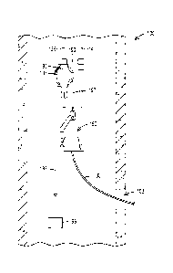
FIG. 1 illustrates an exemplary equipment tower 100 in accordance with an
embodiment of the present invention. The tower 100 is a wind turbine tower,
which
supports various types of equipment. Such equipment may be affixed at or
proximate
the top of the tower 100 or other desired locations along the length of the
tower 100
depending on a particular application. Tower 100 may include a foundation 102,
a
bottom tower portion 104, a middle tower portion 106, a top tower portion 108
and a
steel tip adapter 110. Each tower portion 104, 106, 108 may be formed with a
plurality
of tower segments 105, 107, 109, respectively, that may be formed of precast
concrete.
In an exemplary embodiment of the invention, each tower segment 105 may have a
first
3
84211828
constant diameter and a first height, each tower segment 107 may have a second
constant diameter and a second height, and each tower segment 109 may have a
third
constant diameter and a third height. As illustrated in FIG. 1, the first
constant diameter
of tower segments 105 may be greater than the second constant diameter of
tower
segments 107, which in turn may be greater than the third constant diameter of
tower
segments 109, thereby forming an equipment tower 100 that decreases in
diameter
from the bottom tower portion 104 to the top tower portion 108. Transition
segments
114 and 116 may be positioned between appropriate tower portions 104, 106, 108
to
accommodate the progressive step down in the diameter of tower segments 105,
107,
109 from bottom to top of tower 100.
With continuing reference to FIG. 1, steel tip adapter 110 may connect to the
topmost concrete annular tower segment of the tower 100. The steel tip adapter
110
may also connect with commercially available equipment having various
functions, such
as those typically used in a wind turbine. Such equipment could include rotor
blades, a
rotor, a drivetrain, a gearbox, a generator, an electrical system, a nacelle,
controls, and
other types of equipment use to convert the wind's kinetic energy into
electrical energy.
Tower segments 105, 107, 109 may be precast concrete each having constant
diameters and heights. Tower segments 105, 107, 109 may also be match cast
together to achieve a precision fit between adjacent sections. Such match cast
joints
may incorporate a shear key configuration used to transfer shear across the
segment
joints under transverse loads to the equipment tower 100 and to assist with
aligning
segments with each other during construction. An exemplary match cast
configuration
is disclosed in United States Patent No. 9,175,670 issued to Lockwood et al.
In some instances, epoxy may be
applied onto a segment joint prior to closing the gap between two segments.
The epoxy
may lubricate the annular face of the segments when placing sections on top of
one
another then seal the joint after the epoxy cures. Further, grout may be used
to secure
tower segments 105, 107, 109 together depending on site specific parameters.
FIG. 1 fOrther illustrates foundation 102 that may include a platform 118 and
a
tapered subsection 126. A pedestal or plinth 120 may extend out of platform
118 and
have an inside surface that defines an internal chamber 124. The tapered
subsection
4
CA 2998110 2019-06-07
CA 02998110 2018-03-08
WO 2017/039975 PCT/US2016/046104
126 may extend from platform 118 so it is located below ground level 128. In
the
construction of tower 100, a base of the tapered subsection 126 may be round,
square,
polygonal or other appropriate shapes depending on site specific parameters.
The top
portion of subsection 126 may be rounded or formed with a plurality of
contiguous flat
surfaces as the site specific parameters require. Foundation 102 may be cast-
in-place
then, after the concrete is cured, subsection 118 may be back filled with dirt
to cover its
top surface.
FIG. 2 illustrates a cross section of the exemplary tower 100 of FIG. 1 having
multiple post-tensioning tendons 130 extending from foundation 102 to a top
most tower
segment 132. As best illustrated in FIGS. 3 and 4, a first end 131 of each
tendon 130
may be connected by conventional techniques with foundation 102 by attachment
with a
respective pair of lower anchor rods 134 anchored in foundation 102 via an
embedded
ring 136. A second end 138 of each tendon 130 may be connected by conventional
techniques with topmost tower segment 132 by attachment with a respective pair
139,
141 of upper anchor rods 140 that may be embedded within a diaphragm portion
142 of
top most tower segment 132.
In an exemplary embodiment of the present invention, post-tensioning tendons
130 may be aligned with the length of tower 100 and reside within the central
opening
101 of tower 100. Post-tensioning tendons 130 put the annular tower segments
105,
107, 109 and transition segments 114, 116 into compression. While an exemplary
embodiment of the present invention allows for the second end 138 of each
respective
tendon 130 to be connected with top most tower segment 132, alternate
embodiments
allow for the second end138 of one or more respective tendons 130 to be
connected
with any appropriate tower segment 105, 107, 109 and/or transition segments
114, 116
as a function of the tower design parameters. Similarly, first end 131 of one
or more
tendons 130 may be anchored to tower segments other than to tower platform
118.
Those skilled in the art will recognize that first and second ends 131, 138 of
tendons
130 may be connected to various tower segments in various combinations as a
function
of site specific and/or tower specific parameters.
An advantage of exemplary embodiments of the present invention is that post-
tensioning tendons 130 may be installed during construction of tower 100
without
CA 02998110 2018-03-08
WO 2017/039975 PCT/US2016/046104
dependence on the use of a conventional crane. Taking a crane off the critical
construction path allows for flexibility in scheduling the installation of
tendons 130,
which can increase construction efficiencies and reduce construction costs.
During
construction, a second end 138 of a post-tensioning tendon 130 may be brought
into
central opening 101 of tower 100 through a door 103 (FIG. 12) or another type
of
opening located near the bottom of tower 100. Referring primarily to FIG. 12,
second
end 138 of tendon 130 may be connected with a hoisting cable 197 while a
portion of
the tendon 130 remains outside tower 100. A stand-alone winch 199 operably
connected with the hoisting cable 197 and secured in place at the bottom of
tower 100
may be activated causing the hoisting cable 197 to wind around a spool of the
winch
assembly. With the winch 199 activated, the hoisting cable 197 lifts second
end 138 of
tendon 130 to an attachment point, such as to upper anchor rods 140 of upper
segment
132, and may simultaneously pull the remaining portion of tendon 130 into
central
opening 101. With second end 138 attached to anchor rods 140, first end 131 of
tendon 130 may be attached to lower anchor rods 130. Post-tensioning tendon
130
may then be stressed to desired loads and the process repeated.
FIG. 5 illustrates a perspective view of an exemplary hook or carriage
assembly
150 in accordance with aspects of the invention. Carriage assembly 150 may
include a
shank 152 and a bearing plate platform 154 transversely oriented with respect
to a
vertical portions 156 of shank 152. Shank 152 may be configured with
deflecting
surfaces 158 connected with vertical portions 156. In an exemplary embodiment
of the
present invention, deflecting surfaces 158 may form an obtuse angle with
vertical
portions 156 to encourage carriage assembly 150 to deflect away from a second
end
138 of a post-tensioning tendon 130 when post-tensioning tendon 130 is
connected with
anchor rods 140 as more fully described hereinafter. In an exemplary
embodiment, the
obtuse angle may be between about 130 degrees to 150 degrees, or between about
135 degrees to 145 degrees.
As shown in FIG. 5, deflecting surface 158 is a linear surface formed on a
portion
of shank 152. Alternate embodiments of the invention allow for deflecting
surface 158
to be nonlinear such as a surface having a constant or variable radius of
curvature
depending on the size and shape of a bearing plate 170 (FIG. 4) and the
configuration
6
CA 02998110 2018-03-08
WO 2017/039975 PCT/US2016/046104
of the anchor rods to which it will be attached. For example, deflecting
surface 158 may
be formed as a camming surface configured to ensure bearing plate 170 is
released
from carriage assembly 150 after bearing plate 170 is fixed in place and the
assembly
150 is being lowered.
Carriage assembly 150 is illustrated having a plurality of straps 160 that may
be
configured to be releasably connected with pins or dowels 162 extending from
plate
platform 154. Plate platform 154 may be formed by a first arm 164 and a second
arm
166 each extending substantially perpendicularly from respective vertical
portions 156
that form a relatively flat surface to provide a level area for supporting
bearing plate
170. Plate platform 154 may take on alternate configurations provided that
bearing
plate 170 can be supported in a relatively flat or horizontal position while
being lifted.
Straps160 may be configured and sized to ensure that a bearing plate 170 may
be
releasably held against bearing plate platform 154 when bearing plate 170 is
being lifted
toward the top most tower segment 132 for attachment to upper anchor rods 140.
Straps 160 may be made from various materials and may be releasably attachable
to
dowels 162 so that bearing plate 170 may be placed on plate platform 154 and
secured
thereon for lifting to the top most tower segment 132. Other attachment
mechanisms
may be used instead of straps 160 such as magnets, snaps, clamps, compressive
fit
mechanisms, levers, pins, other types of attachment mechanisms, of
combinations
thereof. In other embodiments, a first attachment mechanism may be associated
with
the first arm 164 and a second attachment mechanism with second arm 166.
FIG. 6 illustrates a side view of carriage assembly 150 where straps 160 may
extend all the way to an end portion 168 of first and second arms 164, 166, at
which
point respective straps 160 may be releasably attachable to dowels 162. FIG. 6
further
illustrates that carriage assembly 150 may include a top portion 172 extending
from a
shank 152 through which a pivot rod 174 may be inserted. A flange 176 may be
connected to pivot rod 174 to allow carriage assembly 150 to pivot about pivot
rod 174.
A looped hook 178 may be attached to flange 176 to which a hoisting cable may
be
attached for lifting carriage assembly 150 toward the top most tower segment
132 or
other desired tower segment. Carriage assembly 150 may include a locking
mechanism 179, as best shown in FIG. 5, for locking the carriage assembly 150
in fixed
7
CA 02998110 2018-03-08
WO 2017/039975 PCT/US2016/046104
relation with flange 176 so that carriage 150 does not pivot about pivot pin
174 when
carriage assembly 150 is being lifted toward a tower segment with a bearing
plate 170
held on bearing plate platform 154.
Bearing plate 170 may include anchor rod apertures (169, 171) or openings
through which upper anchor rods 140 may be inserted for securing bearing plate
170 in
place. Bearing plate 170 may also include an aperture or opening through which
the
second end 138 of a post-tensioning tendon 130 may be inserted for securing
the
tendon 130 to the bearing plate 170. With bearing plate 170 secured within
carriage
assembly 150, it may be hoisted toward anchor rods 140 so that the anchor rod
openings in bearing plate 170 are aligned with the ends of anchor rods 140.
Once
bearing plate 170 is attached to upper anchor rods 140, locking mechanism 179
may be
unlocked thereby allowing carriage assembly 150 to pivot about pivot rod 174.
Pivot
rod 174 may be of sufficient length to allow for carriage assembly 150 to be
laterally
translated on pivot rod 174 so that apertures or openings formed in bearing
plate 170
may be aligned with upper anchor rods 140.
FIG. 7 illustrates an example of bearing plate 170 being released from
carriage
assembly 150 after bearing plate 170 is secured to upper anchor rods 140.
Bearing
plate 170 may be released from bearing plate platform 154 by releasing straps
160 or
other attachment mechanisms. Carriage assembly 150 may be moved away from the
bearing plate 170 by lowering assembly 150 straight down. In this respect,
carriage
assembly 150 is being lowered from a height to which it was raised for
securing bearing
plate 170 to upper anchor rods 140. As carriage assembly 150 is lowered,
deflecting
surface 158 makes contact with or impinges upon bearing plate 170. This
contact
combined with the continuous downward motion of flange 176 causes the carriage
assembly 150 to pivot about pivot rod 174 and move to the side. As carriage
assembly
150 moves to the side, it moves away from bearing plate 170, thereby
accelerating the
disconnection between carriage assembly 150 and bearing plate 170. This avoids
or
minimizes the need for a human being to disengage the carriage assembly from
the
bearing plate/tendon. The angle of deflecting surface 158 determines the rate
at which
the carriage assembly 150 rotates as carriage assembly 150 is being lowered.
In
alternate embodiments, locking mechanism 179 may remain locked or carriage
8
CA 02998110 2018-03-08
WO 2017/039975 PCT/US2016/046104
assembly 150 may be rigidly connected with a hoisting cable 197 in which case
the
cable 197 may just bend to the side as a result of the interaction of the
deflecting
surface 158 and the bearing plate 170.
FIG. 8 illustrates a perspective view of an exemplary sheave assembly 180 in
accordance with aspects of the present invention. Sheave assembly 180 may
include a
first clasp or shackle 182 and a second clasp or shackle 184 for maintaining
sheave
assembly 180 in relation to a respective pair of anchor bars such as upper
anchor bars
140. Shackles 182, 184, which may be configured as split round clamps, may be
clasped or otherwise secured around respective upper anchor bars 140 via
hinges 185
and cotter pins 186. A stability bar such as horizontal stability bar 190 may
be fitted
between shackles 182, 184 for holding them in position relative to each other.
Stability
bar 190 may be releasably attachable at each end to a respective shackle 182,
184 via
conventional attachment mechanisms. Stability bar 190 may have an adjustable
length,
such as a turnbuckle, for adjusting a distance between shackles 182, 184, such
as
when they are being positioned on respective upper anchor bars 140. Once
positioned
on respective upper anchor bars 140, the turnbuckle may be used for expanding
or
contracting the distance between bars 140 to facilitate the alignment of bars
140 with
respective apertures formed within a bearing plate 170 to be attached to those
bars
140.
Sheave assembly 180 may include an upper anchor rod nut 192 and a lower
anchor rod nut 194. Nuts 192, 194 may be compression nuts configured for
securing
sheave assembly 180 in place on respective upper anchor rods 140 and
maintaining
sheave assembly 180 in place at a determined height for lifting bearing plate
170 into
place. Sheave assembly 180 may include sheave frame 196 on which sheave or
pulley
198 may be mounted. Pulley 198 may be fixed in an offset position with respect
to
horizontal stability bar 190 to allow for carriage assembly 150 to lift
bearing plate 170
into proper position with respect to upper anchor rods 140. Sheave frame 196
may
include a clasp or shackle 200, which may be configured as a split round clamp
that
may be clasped or otherwise secured around a respective upper anchor bar 140
via
hinges 202 and associated cotter pins 204.
9
CA 02998110 2018-03-08
WO 2017/039975 PCT/US2016/046104
FIG. 9 illustrates a side view of sheave assembly 180 secured in place on a
pair
of upper anchor rods 140. Sheave frame 196 may house pulley 198 and is secured
to
an upper anchor rod by shackles 182, 200, which can be removed and reused from
one
pair of anchor rods 140 to another pair of anchor rods 140 for installation of
a plurality of
post-tensioning tendons 130. Shackles 182, 184, 200 may be hinged and pinned
to
allow for their removal and consequently removal of the sheave frame 196.
Shackles
182, 200 may be supported vertically on anchor rods 140 by compression nuts
192,
194, which may be of a removable or a permanent type. Horizontal stability bar
190
prevents the sheave assembly components from torqueing (rotating horizontally)
during
a lifting operation. FIG. 10 illustrates a bottom view of sheave assembly 180
secured in
place on a pair of upper anchor rods 140.
FIGs. 11-15 illustrate a sequence of steps for stressing a post-tensioning
tendon
130 within tower 100 in accordance with aspects of the invention. FIG. 11
illustrates a
front view of two hydraulic rams or double action jacks 210 each positioned on
a
respective one of a pair of lower anchor rods 134 embedded within tower
platform 118.
FIG. 11 shows a starting position of jacks 210 for stressing a post-tensioning
tendon
130 after an upper end 138 of tendon 130 has been secured to a pair of upper
anchor
rods 140 via a bearing plate 170 and carriage assembly 150 has been moved away
from bearing plate 170. Each jack 210 may be positioned between a stressing
chair
212 and a temporary upper nut 214 against which jack 210 may be stressed to
force a
lower bearing plate 215 downwardly toward tower platform 118. Stressing chairs
212
allow access to a lower nut 216, as shown in the side view of FIG. 12,
positioned on
each one of the pair of lower anchor rods 134.
The side view of FIG. 13 shows that jacks 210 have been extended from their
starting position to force lower bearing plate 215 toward tower platform 118
thereby
stressing post-tensioning tendon 130. Once lower bearing plate 215 has been
moved a
desired distance then lower nuts 216 may be turned down against the bearing
plate
215, jacks 210 may be retracted and temporary upper nuts 214 turned down
against
jacks 210 as shown in side view of FIG. 14. FIG. 11E illustrates jacks 210
being
extended again to continue stressing post-tensioning tendon 130. The sequence
of
steps illustrated in FIGS. 12-15 may be repeated as many times as necessary to
CA 02998110 2018-03-08
WO 2017/039975 PCT/US2016/046104
achieve proper stressing of tendon 130. Once tendon 130 is fully stressed to
its
required load, jacks 210 may be relaxed, upper nuts 214 may be removed then
the
jacks 210 and stressing chairs 212 may be removed.
FIG. 16 is a schematic illustrating sheave frame 196 mounted on an upper
anchor rod 139 with horizontal stability bar 190 spanning the distance between
the pair
of upper anchor rods 139, 141. Pulley 198 is positioned at an angle from upper
anchor
rods 140 to allow for a direct centerline position of a hoisting cable 197 for
lifting objects
between the upper anchor rods 140. FIG. 12 illustrates a first end of hoisting
cable 197
operably connected with a stand-alone winch 199 for unwinding and winding the
hoisting cable 197. Cable 197 may be threaded through pulley 198 with a second
end
of cable 197 releasably attached to carriage assembly 150. Post-tensioning
tendon 130
may have a first end releasably attached to carriage assembly 150. In an
exemplary
embodiment, a bearing plate 170 (FIG. 4) may be releasably secured within
carriage
assembly 150 so that when winch 199 is activated, hoisting cable will lift the
bearing
plate 170 for attachment to upper bearing rods 140. The position of pulley 198
relative
to upper anchor rods 140 allows for apertures within bearing plate 170 to be
in
substantial alignment with upper anchor rods 140 for attachment of bearing
plate 170 to
the upper anchor rods 140. Substantial alignment, as used herein, means that
the
anchor rods can be inserted through the apertures with no or light mechanical
restriction
which can be overcome by the pulling force exerted by the cable.
While various embodiments of the present invention have been shown and
described herein, it will be obvious that such embodiments are provided by way
of
example only. Numerous variations, changes and substitutions may be made
without
departing from the invention herein. Accordingly, it is intended that the
invention be
limited only by the spirit and scope of the appended claims.
11