Note: Descriptions are shown in the official language in which they were submitted.
CA 02998256 2018-03-09
WO 2017/042297
PCT/EP2016/071234
- 1 -
MULTI-SEGMENT COMPONENT FOR AN AEROSOL-GENERATING ARTICLE
The present invention relates to a multi-segment component for an aerosol
generating
article. In particular, the present invention relates to a multi-segment
components having a
combustible heat source for heating an aerosol-forming substrate downstream of
the
combustible heat source, and a wrapper circumscribing at least a rear portion
of the
combustible heat source. The present invention also relates to combustible
heat sources for
such multi-segment components and to aerosol generating comprising such multi-
segment
components.
A number of smoking articles in which tobacco is heated rather than combusted
have
been proposed in the art. An aim of such 'heated' smoking articles is to
reduce known harmful
smoke constituents of the type produced by the combustion and pyrolytic
degradation of
tobacco in conventional cigarettes. In one known type of heated smoking
article, an aerosol is
generated by the transfer of heat from a combustible heat source to a
physically separate
aerosol-forming substrate, such as a tobacco-containing substrate. The aerosol-
forming
substrate may be located within, around or downstream of the combustible heat
source. During
smoking, volatile compounds are released from the aerosol-forming substrate by
heat transfer
from the combustible heat source and entrained in air drawn through the
smoking article. As
the released compounds cool, they condense to form an aerosol that is inhaled
by the user.
For example, WO-A2-2009/022232 discloses a smoking article comprising a
combustible
heat source, an aerosol-forming substrate downstream of the combustible heat
source, and a
heat-conducting element around and in contact with a rear portion of the
combustible heat
source and an adjacent front portion of the aerosol-forming substrate. The
combustible heat
source and the aerosol-forming substrate are in abutting coaxial alignment
and, along with the
heat-conducting element, are overwrapped in an outer wrapper of cigarette
paper of low air
permeability to hold the various components of the smoking article together.
In use, the front
portion of the aerosol-forming substrate is heated primarily by conduction
through the abutting
rear portion of the combustible heat source and via the heat-conducting
element.
Apparatus and processes for manufacturing aerosol generating articles
consisting of a
plurality of components are known in the art. For example, EP 2 210 509 Al
discloses a linear
process for combining components of a smoking article, such as the heat
source, aerosol
generating substrate, expansion chamber, for the production of untipped
smoking articles. The
method comprises feeding a stream of components along a moving delivery path;
compacting
the stream of components into groups of two or more different components,
wrapping the
components in a web of material; and cutting the web of material in each space
between groups
of components to form multi-segment components including all of the components
of the
CA 02998256 2018-03-09
WO 2017/042297
PCT/EP2016/071234
- 2 -
smoking article, except for the mouthpiece. The multi-segment components, or
untipped
smoking articles, are then attached to single mouthpieces by wrapping the
untipped smoking
article and the mouthpiece with tipping paper in a tipping machine to produce
a finished
smoking article.
In another example, WO-A1-2013/164124 discloses feeding a stream of first
multi-
segment components formed using a similar process to that described in EP 2
210 509 A1,
each comprising a combustible heat source, an aerosol-forming substrate and an
airflow
directing segment, onto a receiving means, and feeding a stream of second
multi-segment
components, each comprising a mouthpiece and at least one further segment,
onto the
receiving means. The first multi-segment component and second multi-segment
component are
combined by wrapping the first multi-segment component and the second multi-
segment
component in a web material to form an individual smoking article having a
combustible heat
source at a first end and a mouthpiece at a second end.
In aerosol generating articles in which an aerosol forming substrate, for
example tobacco
is heated rather than combusted, the temperature attained in the aerosol-
forming substrate has
a significant impact on the ability to generate a sensorially acceptable
aerosol. It is typically
desirable to maintain the temperature of the aerosol-forming substrate within
a certain range in
order to optimise the aerosol delivery to a user. In some cases, the
combustible heat source
may become dislodged such that its position relative to the aerosol-forming
substrate is altered.
This may cause the temperature of the aerosol-forming substrate to drop
outside of a desired
range, thereby impacting the performance of the smoking article. If the
temperature of the
aerosol-forming substrate drops too low, for instance, it may adversely impact
the consistency
and the amount of aerosol delivered to a user.
It would be desirable to provide a multi-segment component for an aerosol
generating
article comprising a combustible heat source with improved retention.
According to the present invention, there is provided a multi-segment
component for an
aerosol generating article, the multi-segment component comprising: a
combustible heat
source; an aerosol-forming substrate downstream of the combustible heat
source; and a
wrapper circumscribing the combustible heat source along at least part of its
length; wherein the
multi-segment component further comprises an intumescent layer between the
combustible
heat source and the wrapper and circumscribing the combustible heat source,
the intumescent
layer being formed from an intumescent inorganic glue. The intumescent
inorganic glue may
expand when heated during combustion of the combustible heat source.
Advantageously, in examples of aspects of the invention, improved retention of
the
combustible heat source in the wrapper may be achieved. The retention may be
improved, for
example during or after combustion of the combustible heat source compared
with the
CA 02998256 2018-03-09
WO 2017/042297
PCT/EP2016/071234
- 3 -
intumescent inorganic glue not being present. This may assist or ensure
correct positioning of
the combustible heat source for desirable aerosol properties. Preferably, the
presence of
intumescent inorganic glue acts to hold the combustible heat source in the
wrapper or improves
the holding of the combustible heat source in the wrapper compared with an
example in which
the intumescent inorganic glue is not present. As the intumescent layer is
formed from an
intumescent inorganic glue, there may be little or no significant loss of
material or volume during
combustion of the heat source. In some cases there may be no significant
reduction in
adhesion between the intumescent inorganic glue and the combustible heat
source.
The intumescent inorganic glue may or may not form a bond with one or more of
the
surfaces in which it is in contact.
The presence of the intumescent layer can improve or ensure that the heat
source is
tightly held in the wrapper during use.
Further, the intumescent layer can expand to
compensate for any gap between the combustible heat source and the wrapper,
for example as
a result of thermal expansion of the wrapper during use. This can reduce the
bypass of
combustion gases around the combustible heat source.
The intumescent layer may contact the combustible heat source indirectly via
one or more
intermediate components. In preferred embodiments, the intumescent layer is in
direct contact
with the combustible heat source. With this arrangement, the intumescent layer
may
compensate for the surface roughness or geometry defects of the combustible
heat source and
may reduce the bypass of combustion gases around the combustible heat source.
The intumescent layer circumscribes the combustible heat source.
As used herein, the terms "circumscribe" and "circumscribing" are given their
usual
meanings to mean "extending around the entire circumference". Thus, by
"circumscribing" the
combustible heat source, the intumescent layer extends around the entire
circumference of the
combustible heat source.
This can have the advantage that the intumescent layer forms a continuous ring
around
the combustible heat source, and thus bypass of combustible gases around the
heat source
may be reduced. Consequently, the resistance-to-draw, or "RTD", of the aerosol-
generating
article may be maintained. Where the combustible heat source is a blind
combustible heat
source and the aerosol-generating article includes one or more air inlets
through which air may
be drawn into the aerosol-forming substrate, this arrangement ensures that
substantially all of
the airflow during use enters the aerosol-forming substrate through the air
inlets, for desirable
aerosol properties.
The intumescent inorganic glue may have any suitable expansion ratio. For
example, the
intumescent inorganic glue may have an expansion ratio of at least about
1.5:1, preferably from
CA 02998256 2018-03-09
WO 2017/042297
PCT/EP2016/071234
- 4 -
about 2:1 to about 5:1, most preferably about 3:1, when heated from 20 degrees
Celsius to 700
degrees Celsius at ambient pressure.
The intumescent layer may have any suitable thickness.
In certain preferred
embodiments, the intumescent layer has a thickness of from at least about 0.01
mm to about
0.1mm, preferably from about 0.01 mm to about 0.04 mm, more preferably has a
minimum
thickness of about 0.02 mm. Such thicknesses have been found to be
particularly effective in
some examples. For example, a minimum thickness of about 0.02 mm will be
sufficient in many
examples to compensate for combustible heat source geometry defects of up to
0.05 mm.
Where the combustible heat source includes one or more recesses the thickness
may be
measured at a region of the heat source not including the recess. In some
cases the thickness
of the intumescent layer may change between the application of the layer
during manufacture
and for the multi-segment component or aerosol generating article. For
example, the thickness
of layer applied during manufacture may be chosen such that the thickness of
the intumescent
layer in the multi-segment component or aerosol generating article is at least
about 0.01 mm,
for example less than 0.1 mm.
The intumescent inorganic glue may be a foaming intumescent inorganic glue.
The intumescent inorganic glue may have any suitable composition. In certain
preferred
embodiments, the intumescent inorganic glue of the multi-segment component or
of the aerosol
generating article comprises at least 1% by weight of water, preferably
between about 1% and
about 7% by weight of water, more preferably from about VA to about 5% by
weight of water.
Vaporisation of the water in the intumescent inorganic glue on heating during
combustion of the
combustible heat source may cause bubbles to form, thus expanding or foaming
the
intumescent inorganic glue. It will be understood that such intumescent
inorganic glues may
have a higher water content when supplied for manufacture of the multi-segment
component,
and when applied during manufacture of the multi-segment component or of the
aerosol
generating article. The water content of the intumescent inorganic glue may
reduce when the
intumescent inorganic glue dries out following application during manufacture.
For example, the
intumescent inorganic glue may comprise 60% by weight of water when initially
supplied but
may subsequently comprise 30% by weight of water or less after the intumescent
inorganic glue
has been deposited and dried or partially dried. .
Preferably the intumescent layer is formed from a sodium silicate glue.
In certain embodiments, the intumescent layer is formed from a sodium silicate
glue
having a molar ratio of from about 2 to about 3.5 parts Si02 to 1 part Na20.
The intumescent inorganic glue may be applied directly onto an outer surface
of the
combustible heat source. In such examples, the outer surface of the
combustible heat source
may be substantially continuous. In certain preferred embodiments, the
combustible heat
CA 02998256 2018-03-09
WO 2017/042297
PCT/EP2016/071234
- 5 -
source has at least one shaped recess on its outer surface, and wherein the
intumescent
inorganic glue of the intumescent layer at least partially fills the shaped
recess.
With this arrangement, the retention of the combustible heat source within the
wrapper
may be further improved. This may help to ensure correct positioning of the
combustible heat
source and, thus, desirable aerosol properties.
In certain embodiments, the at least one shaped recess comprises at least one
longitudinal groove. This arrangement may be particularly effective since the
groove is aligned
parallel to the direction along which undesirable movement of the combustible
heat source may
occur and thus increases the retention force applied by the intumescent
inorganic glue to the
combustible heat source in the longitudinal direction.
In certain embodiments, the at least one longitudinal groove comprises a
plurality of
circumferentially spaced apart longitudinal grooves.
In certain embodiments, the depth of the at least one shaped recess is less
than about 10
percent of the outer diameter of the combustible heat source. This has the
advantage that the
mass of the heat source, and consequently its heating performance, is
substantially unaffected
by the presence of the recess. Additionally, the time required for the
intumescent inorganic glue
to dry after its application may be reduced, improving manufacturability.
In some examples, the depth of the at least one shaped recess is between about
0.05 mm
and about 0.8 mm, for example between about 0.2 mm and 0.4 mm.
In certain embodiments, the depth of the at least one shaped recess decreases
towards
its downstream end. This has the advantage that the retention of the heat
source can be further
improved as the intumescent inorganic glue may act as a wedge to resist
upstream movement
of the heat source relative to the wrapper. It has also been found to result
in improved filling of
the at least one recess by the intumescent inorganic glue, since the
intumescent inorganic glue
more easily flows along the length of the recess during manufacture.
In such examples, the depth of the at least one shaped recess may decrease
gradually
along a transition portion, or in a stepwise manner.
In certain embodiments, the combustible heat source comprises a rear portion
having a
substantially constant cross-section, the at least one recess terminating at
the upstream end of
the rear portion. With this arrangement, the at least one recess does not
extend into the rear
portion and, consequently, the rear portion forms a barrier to reduce the
bypass of combustion
gases around the heat source in the downstream direction. The rear portion may
define the
maximum outer diameter of the combustible heat source. Such an arrangement may
improve
ease of manufacture by making it easier to wrap the wrapper around the heat
source. It may
also improve conductive heat transfer from the heat source to the wrapper.
This may be
particularly advantageous in examples of multi-segment component in which the
wrapper
CA 02998256 2018-03-09
WO 2017/042297
PCT/EP2016/071234
- 6 -
comprises a heat-conducting layer for transferring thermal energy from the
combustible heat
source to the aerosol-forming substrate.
The rear portion of the combustible heat source may have any suitable
dimensions. In
certain preferred embodiments, the rear portion has a length of less than
about 3 mm,
preferably of from about 2 mm to about 3 mm.
In certain preferred embodiments, the radially outer edges of the at least one
shaped
recess are curved with a radius of curvature of at least about 0.05 mm. This
may
advantageously result in improved filling of the recess by the glue. It may
also result in a
reduction in the visibility of the at least one recess through the wrapper and
reduce the risk of
damage to the wrapper caused by the radially outer edges of the at least one
recess during
wrapping. Furthermore, with this arrangement, the radially outer edges of the
combustible heat
source are less likely to be damaged or break off during manufacture, reducing
the amount of
dust, such as carbon dust, generated during manufacture. Preferably, the
radius of curvature is
from about 0.05 mm to about 0.5 mm, more preferably from about 0.2 mm to about
0.4 mm.
In some examples, the number of shaped recesses may be from 8 to 17,
preferably from
12 to 16. In some examples of the invention, the shaped recesses are
substantially evenly
spaced around the periphery of the combustible heat source.
The outer diameter of the combustible heat source may vary along its length.
In certain
embodiments, the outer diameter of the combustible heat source is
substantially constant along
substantially the entire length of the combustible heat source. This may
result in improved
ma nufactu rability.
The multi-segment component comprises a wrapper circumscribing the combustible
heat
source along at least part of its length. The wrapper may be formed from one
or more
elements. For example, the wrapper may be formed from a single sheet of
material.
In some embodiments, the wrapper comprises one or more layers of heat-
conductive
material. Preferably, the one or more layers of heat-conductive material are
positioned around
at least a rear portion of the combustible heat source and at least a front
portion of the aerosol-
forming substrate. In such embodiments, the heat-conductive material provides
a thermal link
between the combustible heat source and the aerosol-forming substrate and
advantageously
helps to facilitate adequate heat transfer from the combustible heat source to
the aerosol-
forming substrate to provide an acceptable aerosol. The heat-conductive
material may be in
direct contact with one or both of the combustible heat source and the aerosol-
forming
substrate. Alternatively or in addition, the layer of heat-conductive material
may be spaced
apart from one or both of the combustible heat source and the aerosol-forming
substrate, such
that there is no direct contact between the heat-conductive material and one
or both of the
combustible heat source and the aerosol-forming substrate.
CA 02998256 2018-03-09
WO 2017/042297
PCT/EP2016/071234
- 7 -
The one or more layers of heat-conductive material are preferably non-
combustible. In
certain embodiments, the one or more layers of heat-conductive material may be
oxygen
restricting. In other words, the one or more layers of heat-conductive
material may inhibit or
resist the passage of oxygen through the wrapper.
Suitable heat-conductive materials for use in multi-segment components
according to the
invention include, but are not limited to: metal foil wrappers such as, for
example, aluminium foil
wrappers, steel wrappers, iron foil wrappers and copper foil wrappers; and
metal alloy foil
wrappers.
In some embodiments, the wrapper comprises one or more layers of heat-
insulative
material. With this arrangement, the heat-insulative material reduces the heat
transfer from the
combustible heat source to an outer surface of the wrapper, reducing the
temperature of the
surface of aerosol generating article.
Preferably, the heat-insulative material is non-
combustible. Inclusion of a non-combustible, heat insulating layer
advantageously helps to
reduce the ignition propensity of aerosol generating articles comprising multi-
segment
components according to the invention by reducing the temperature of the
surface of the
aerosol generating article.
The wrapper may be a laminate wrapper formed from a plurality of layers.
The wrapper may comprise a radially outer layer of heat-conductive material
and a radially
inner layer of heat-insulative material. In some embodiments, the wrapper
comprises a radially
inner layer of heat-conductive material and a radially outer layer of heat-
insulative material.
Other arrangements are possible. In preferred arrangements, the wrapper may
advantageously
conduct heat from the combustible heat source to the aerosol-forming
substrate, while
controlling radiative heat loss from the combustible heat source and the
combustible heat
source.
As used herein, the term "intumescent layer" denotes a layer which expands
upon
exposure to elevated temperatures, other than only as a result of its
coefficient of thermal
expansion.
As used herein, the term "inorganic glue" refers to an adhesive, or
combination of
adhesives, which is substantially free of carbon.
As used herein, the term "expansion ratio" refers to the ratio of the
thickness of the
intumescent layer before expansion to the thickness of the intumescent layer
after expansion.
As used herein, the phrase "intumescent layer has a thickness of" refers to
the dimension
of the layer in the radial direction.
As used herein, the term "longitudinal" is used to describe the direction
between the
proximal end and the opposed distal end of the smoking article.
CA 02998256 2018-03-09
WO 2017/042297
PCT/EP2016/071234
- 8 -
As used herein, the terms "radial" and "transverse" are used to describe the
direction
perpendicular to the direction between the proximal end and the opposed distal
end of the
smoking article.
As used herein, the term "length" is used to describe the maximum dimension in
the
longitudinal direction of the smoking article. That is, the maximum dimension
in the direction
between the proximal end and the opposed distal end of the smoking article in
the direction
between the proximal end and the opposed distal end of the smoking article.
As used herein, the term "thickness" refers to the maximum dimension of the
intumescent
layer in the radial direction.
As used herein, the term "groove" refers to an elongate depression in the
surface of the
heat source.
As used herein, the term "shaped recess" refers to a recess with predetermined
dimensions which is deliberately formed in the outer surface of the
combustible heat source.
As used herein, the term "diameter" denotes the maximum transverse dimension
of
elongate combustible heat sources according to the invention.
As used herein, the phrase "the depth of the at least one recess decreases
towards its
downstream end" means that the depth of each recess at a first location along
its length is
greater than the depth of each recess at a second location downstream of the
first location.
This includes embodiments in which the depth of each recess is greatest at or
proximal to its
upstream end, as well as embodiments in which the depth of each recess is
greatest at a point
between its upstream and downstream ends
As used herein, the phrase "the outer diameter of the combustible heat source
is
substantially constant" means that the outer envelope of the heat source, that
is, the smallest
space within which the heat source can be accommodated, remains substantially
the same
along the length of the heat source.
As used herein, the term "heat-insulative material" is used to describe
material having a
bulk thermal conductivity of less than about 50 milliwatts per metre Kelvin
(mW/(m K)) at 23 C
and a relative humidity of 50% as measured using the modified transient plane
source (MTPS)
method.
As used herein, the term "heat-conductive material" is used to describe a
having a bulk
thermal conductivity of at least about 10 W per metre Kelvin (W/(m K)) at 23 C
and a relative
humidity of 50% as measured using the modified transient plane source (MTPS)
method.
As used herein, the term "aerosol-forming substrate" is used to describe a
substrate
capable of releasing upon heating volatile compounds, which can form an
aerosol.
The aerosols generated from aerosol-forming substrates of multi-segment
components
according to the invention may be visible or invisible and may include vapours
(for example, fine
CA 02998256 2018-03-09
WO 2017/042297
PCT/EP2016/071234
- 9 -
particles of substances, which are in a gaseous state, that are ordinarily
liquid or solid at room
temperature) as well as gases and liquid droplets of condensed vapours.
As used herein, the term "non-combustible" is used to describe a material that
is
substantially non-combustible at temperatures reached by the combustible heat
source during
combustion and ignition thereof.
As used herein, the term "ignition propensity" refers to the tendency of
aerosol generating
articles, such as smoking articles, to cause a substrate on which they lie to
burn. The ignition
propensity should be low enough to eliminate, reduce or almost eliminate the
likelihood of an
aerosol generating article causing a substrate on which it is placed to burn.
The ignition
propensity may be measured according to ISO 12863:2010(E).
The combustible heat source is preferably a solid heat source, and may
comprise any
suitable combustible fuel including, but not limited to, carbon and carbon-
based materials
containing aluminium, magnesium, one or more carbides, one or more nitrides
and
combinations thereof. Solid combustible heat sources for heated smoking
articles and methods
for producing such heat sources are known in the art and described in, for
example, US-A-
5,040,552 and US-A-5,595,577. Typically, known solid combustible heat sources
for heated
smoking articles are carbon-based, that is they comprise carbon as a primary
combustible
material.
The combustible heat source is preferably a blind combustible heat source. As
used
herein, the term "blind" describes a heat source that does not comprise any
air flow channels
extending from the front end face to the rear end face of the combustible heat
source. As used
herein, the term "blind" is also used to describe a combustible heat source
including one or
more airflow channels extending from the front end face of the combustible
heat source to the
rear end face of the combustible heat source, wherein a combustible
substantially air
impermeable barrier between the rear end face of the combustible heat source
and the aerosol-
forming substrate barrier prevents air from being drawn along the length of
the combustible heat
source through the one or more airflow channels.
Multi-segment components according to the invention comprising blind
combustible heat
sources comprise one or more air inlets downstream of the rear end face of the
combustible
heat source for drawing air into the one or more airflow pathways. Multi-
segment components
according to the invention comprising non-blind combustible heat sources may
also comprise
one or more air inlets downstream of the rear end face of the combustible heat
source for
drawing air into the one or more airflow pathways.
In certain preferred embodiments, multi-segment components according to the
invention
comprising blind combustible heat sources comprise one or more air inlets
located proximate to
the downstream end of the aerosol-forming substrate.
CA 02998256 2018-03-09
WO 2017/042297
PCT/EP2016/071234
- 10 -
In use, air drawn along the one or more airflow pathways of aerosol generating
articles
including multi-segment components according to the invention comprising a
blind combustible
heat source for inhalation by a user does not pass through any airflow
channels along the blind
combustible heat source. The lack of any airflow channels through the blind
combustible heat
source advantageously substantially prevents or inhibits activation of
combustion of the blind
combustible heat source during puffing by a user. This substantially prevents
or inhibits spikes
in the temperature of the aerosol-forming substrate during puffing by a user.
By preventing or inhibiting activation of combustion of the blind combustible
heat source,
and so preventing or inhibiting excess temperature increases in the aerosol-
forming substrate,
combustion or pyrolysis of the aerosol-forming substrate under intense puffing
regimes may be
advantageously avoided. In addition, the impact of a user's puffing regime on
the composition
of the mainstream aerosol may be advantageously minimised or reduced.
The inclusion of a blind combustible heat source may also advantageously
substantially
prevent or inhibit combustion and decomposition products and other materials
formed during
ignition and combustion of the blind combustible heat source from entering air
drawn through
multi-segment components according to the invention during use thereof. This
is particularly
advantageous where the blind combustible heat source comprises one or more
additives to aid
ignition or combustion of the blind combustible heat source.
In multi-segment components according to the invention comprising a blind
combustible
heat source, heat transfer from the blind combustible heat source to the
aerosol-forming
substrate occurs primarily by conduction and heating of the aerosol-forming
substrate by forced
convection is minimised or reduced. This may advantageously help to minimise
or reduce the
impact of a user's puffing regime on the composition of the mainstream aerosol
of smoking
articles according to the invention.
In multi-segment components according to the invention comprising a blind
combustible
heat source, it is particularly important to optimise the conductive heat
transfer between the
combustible heat source and the aerosol-forming substrate. As described
further below, the
inclusion of one or more heat-conducting elements around at least a rear
portion of the
combustible carbonaceous heat source and at least a front portion of the
aerosol-forming
substrate is particularly preferred in multi-segment components according to
the invention
including blind heat sources, where there is little if any heating of the
aerosol-forming substrate
by forced convection.
It will be appreciated that multi-segment components according to the
invention may
comprise blind combustible heat sources comprising one or more closed or
blocked
passageways through which air may not be drawn for inhalation by a user.
CA 02998256 2018-03-09
WO 2017/042297
PCT/EP2016/071234
- 11 -
For example, multi-segment components according to the invention may comprise
blind
combustible heat sources comprising one or more closed passageways that extend
from the
front end face at the upstream end of the blind combustible carbonaceous heat
source only part
way along the length of the blind combustible carbonaceous heat source.
The inclusion of one or more closed air passageways increases the surface area
of the
blind combustible heat source that is exposed to oxygen from the air and may
advantageously
facilitate ignition and sustained combustion of the blind combustible heat
source.
In certain embodiments of the invention, the combustible heat source comprises
at least
one longitudinal airflow channel, which provides one or more airflow pathways
through the heat
source. The term "airflow channel" is used herein to describe a channel
extending along the
length of the heat source through which air may be drawn through the smoking
article for
inhalation by a user. Such heat sources including one or more longitudinal
airflow channels are
referred to herein as "non-blind" heat sources.
The diameter of the at least one longitudinal airflow channel may be between
about 1.5
mm and about 3 mm, more preferably between about 2 mm and about 2.5 mm. The
inner
surface of the at least one longitudinal airflow channel may be partially or
entirely coated, as
described in more detail in WO-A-2009/022232.
The aerosol-forming substrate may be a solid aerosol-forming substrate.
Alternatively, the
aerosol-forming substrate may comprise both solid and liquid components. The
aerosol-forming
substrate may comprise a tobacco-containing material containing volatile
tobacco flavour
compounds, which are released from the substrate upon heating. Alternatively,
the aerosol-
forming substrate may comprise a non-tobacco material. The aerosol-forming
substrate may
further comprise one or more aerosol formers. Examples of suitable aerosol
formers include,
but are not limited to, glycerine and propylene glycol.
In some embodiments, the aerosol-forming substrate is a rod comprising a
tobacco-
containing material.
If the aerosol-forming substrate is a solid aerosol-forming substrate, the
solid aerosol-
forming substrate may comprise, for example, one or more of: powder, granules,
pellets,
shreds, spaghetti strands, strips or sheets containing one or more of: herb
leaf, tobacco leaf,
fragments of tobacco ribs, reconstituted tobacco, homogenised tobacco,
extruded tobacco and
expanded tobacco. The solid aerosol-forming substrate may be in loose form, or
may be
provided in a suitable container or cartridge. For example, the aerosol-
forming material of the
solid aerosol-forming substrate may be contained within a paper or other
wrapper and have the
form of a plug. Where an aerosol-forming substrate is in the form of a plug,
the entire plug
including any wrapper may be considered to be the aerosol-forming substrate.
CA 02998256 2018-03-09
WO 2017/042297
PCT/EP2016/071234
- 12 -
Optionally, the solid aerosol-forming substrate may contain additional tobacco
or non-
tobacco volatile flavour compounds, to be released upon heating of the solid
aerosol-forming
substrate. The solid aerosol-forming substrate may also contain capsules that,
for example,
include the additional tobacco or non-tobacco volatile flavour compounds and
such capsules
may melt during heating of the solid aerosol-forming substrate.
Optionally, the solid aerosol-forming substrate may be provided on or embedded
in a
thermally stable carrier. The carrier may take the form of powder, granules,
pellets, shreds,
spaghetti strands, strips or sheets. The solid aerosol-forming substrate may
be deposited on
the surface of the carrier in the form of, for example, a sheet, foam, gel or
slurry. The solid
aerosol-forming substrate may be deposited on the entire surface of the
carrier, or alternatively,
may be deposited in a pattern in order to provide a non-uniform flavour
delivery during use.
The aerosol-forming substrate may be in the form of a plug or segment
comprising a
material capable of emitting volatile compounds in response to heating
circumscribed by a
paper or other wrapper. As stated above, where an aerosol-forming substrate is
in the form of
such a plug or segment, the entire plug or segment including any wrapper is
considered to be
the aerosol-forming substrate.
The aerosol-forming substrate preferably has a length of between about 5 mm
and about
mm. In certain embodiments, the aerosol-forming substrate may have a length of
between
about 6 mm and about 15 mm or a length of between about 7 mm and about 12 mm.
20 In preferred embodiments, the aerosol-forming substrate comprises a plug
of tobacco-
based material wrapped in a plug wrap. In particularly preferred embodiments,
the aerosol-
forming substrate comprises a plug of homogenised tobacco-based material
wrapped in a plug
wrap.
In any of the above embodiments, the combustible heat source and the aerosol-
forming
substrate may be in abutting coaxial alignment. Advantageously, the
intumescent layer can
retain the combustible heat source in direct contact with the aerosol-forming
substrate during
use to ensure a good thermal connection between the two components and to
maintain the
temperature of the aerosol-forming substrate within a desired range.
As used herein, the terms "abutting" and "abut" are used to describe a
component, or a
portion of a component, being in direct contact with another component, or
portion of a
component.
Multi-segment components according to the invention may comprise a heat-
conducting
element around and in direct contact with both at least a rear portion of the
combustible heat
source and at least a front portion of the aerosol-forming substrate. In such
embodiments, the
heat-conducting element provides a thermal link between the combustible heat
source and the
aerosol-forming substrate of smoking articles according to the invention and
advantageously
CA 02998256 2018-03-09
WO 2017/042297
PCT/EP2016/071234
- 13 -
helps to facilitate adequate heat transfer from the combustible heat source to
the aerosol-
forming substrate to provide an acceptable aerosol.
Alternatively or in addition, multi-segment components according to the
invention may
comprise a heat-conducting element spaced apart from one or both of the
combustible heat
source and the aerosol-forming substrate, such that there is no direct contact
between the heat-
conducting element and one or both of the combustible heat source and the
aerosol-forming
substrate.
Where the multi-segment component comprises a heat-conducting element around
at
least a rear portion of the combustible heat source and at least a front
portion of the aerosol-
forming substrate, the heat-conducting element may be formed by the wrapper.
For example,
the wrapper may comprise one or more layers of heat conductive material which
form the one
or more heat-conducting elements.
The one or more heat-conducting elements are preferably non-combustible. In
certain
embodiments, the one or more heat-conducting elements may be oxygen
restricting. In other
words, the one or more heat-conducting elements may inhibit or resist the
passage of oxygen
through the heat-conducting element.
Suitable heat-conducting elements for use in multi-segment components
according to the
invention include, but are not limited to: metal foil wrappers such as, for
example, aluminium foil
wrappers, steel wrappers, iron foil wrappers and copper foil wrappers; and
metal alloy foil
wrappers.
Multi-segment components according to the invention may further comprise a cap
configured to at least partially cover the front end face of the combustible
heat source, wherein
the cap is removable to expose the front end face of the combustible heat
source prior to use of
the smoking article.
As used herein, the term "cap" refers to a protective cover that substantially
surrounds the
distal end of the multi-segment component, including the front end face.
Providing a cap that is
removed prior to ignition of the combustible heat source advantageously
protects the
combustible heat source prior to use.
For example, multi-segment components according to the invention may comprise
a
removable cap attached at a line of weakness to the distal end of the smoking
article, wherein
the cap comprises a cylindrical plug of material circumscribed by a wrapper as
described in
WO-A1-2014/086998.
Multi-segment components according to the present invention may further
comprise a
transfer element, or spacer element, downstream of the aerosol-forming
substrate. Such an
element may take the form of a hollow tube that is located downstream of an
aerosol-forming
substrate.
CA 02998256 2018-03-09
WO 2017/042297
PCT/EP2016/071234
- 14 -
The transfer element may abut the aerosol-forming substrate. Alternatively,
the transfer
element may be spaced apart from the aerosol-forming substrate. The transfer
element may be
coaxial alignment with one or both of the combustible heat source and the
aerosol-forming
substrate.
The inclusion of a transfer element advantageously allows cooling of the
aerosol
generated by heat transfer from the combustible heat source to the aerosol
forming substrate.
The inclusion of a transfer element also advantageously allows the overall
length of an aerosol
generating article comprising a multi-segment component according to the
invention to be
adjusted to a desired value, for example to a length similar to that of a
conventional cigarette,
through an appropriate choice of the length of the transfer element.
The transfer element may have a length of between about 7 mm and about 50 mm,
for
example a length of between about 10 mm and about 45 mm or of between about 15
mm and
about 30 mm. The transfer element may have other lengths depending upon the
desired overall
length of the aerosol generating article, and the presence and length of other
components within
the multi-segment component or an aerosol generating article comprising the
multi-segment
component.
Preferably, the transfer element comprises at least one open-ended tubular
hollow body.
In such embodiments, in use, air drawn into the aerosol generating article
passes through the at
least one open-ended tubular hollow body as it passes downstream through the
aerosol
generating article.
The transfer element may comprise at least one open-ended tubular hollow body
formed
from one or more suitable materials that are substantially thermally stable at
the temperature of
the aerosol generated by the transfer of heat from the combustible heat source
to the aerosol-
forming substrate. Suitable materials are known in the art and include, but
are not limited to,
paper, cardboard, plastics, such a cellulose acetate, ceramics and
combinations thereof.
Alternatively or in addition, multi-segment components according to the
invention may
comprise an aerosol-cooling element or heat exchanger downstream of the
aerosol-forming
substrate. The aerosol-cooling element may comprise a plurality of
longitudinally extending
channels.
The aerosol-cooling element may comprise a gathered sheet of material selected
from the
group consisting of metallic foil, polymeric material, and substantially non-
porous paper or
cardboard. In certain embodiments, the aerosol-cooling element may comprise a
gathered
sheet of material selected from the group consisting of polyethylene (PE),
polypropylene (PP),
polyvinylchloride (PVC), polyethylene terephthalate (PET), polylactic acid
(PLA), cellulose
acetate (CA), and aluminium foil.
CA 02998256 2018-03-09
WO 2017/042297
PCT/EP2016/071234
- 15 -
In certain preferred embodiments, the aerosol-cooling element may comprise a
gathered
sheet of biodegradable polymeric material, such as polylactic acid (PLA) or a
grade of Mater-Bi
(a commercially available family of starch based copolyesters).
Multi-segment components according to the invention comprise a wrapper that
circumscribes the combustible heat source along at least a part of its length.
Preferably, the
wrapper circumscribes at least a front portion of the aerosol-forming
substrate and at least a
rear portion of the combustible heat source.
In preferred embodiments, the wrapper
circumscribes the aerosol-forming substrate, at least a rear portion of the
combustible heat
source and any other components of the smoking article downstream of the
aerosol-forming
substrate.
The wrapper may be formed from any suitable material or combination of
materials.
Suitable materials are well known in the art and include, but are not limited
to, cigarette paper.
According to a second aspect of the invention, there is provided an aerosol-
generating
article comprising a multi-segment component according to any of the
embodiments described
above.
The aerosol-generating article may be a smoking article.
The combustible heat source is located at or proximate to the distal end of
the aerosol-
generating article. The mouth end of the aerosol-generating article is
downstream of the distal
end of the aerosol-generating article. The proximal end of the aerosol-
generating article may
also be referred to as the downstream end of the aerosol-generating article
and the distal end of
the aerosol-generating article may also be referred to as the upstream end of
the aerosol-
generating article. Components, or portions of components, of the aerosol-
generating article
and of the multi-segment component may be described as being upstream or
downstream of
one another based on their relative positions between the proximal end of the
aerosol-
generating article and the distal end of the aerosol-generating article. The
mouth end is
downstream of the distal end.
As used herein, the terms 'upstream' and 'front', and 'downstream' and 'rear',
are used to
describe the relative positions of components, or portions of components of
the multi-segment
component in relation to the direction in which a user draws on an aerosol-
generating article
incorporating the multi-segment component during use thereof. Aerosol-
generating articles
according to the invention comprise a proximal end through which, in use, an
aerosol exits the
aerosol-generating article for delivery to a user. The proximal end of the
aerosol-generating
article may also be referred to as the mouth end. In use, a user draws on the
mouth end of the
aerosol-generating article in order to inhale an aerosol generated by the
aerosol-generating
article.
Aerosol generating articles according to the invention preferably comprise a
mouthpiece
CA 02998256 2018-03-09
WO 2017/042297
PCT/EP2016/071234
- 16 -
located at the proximal end thereof.
Preferably, the mouthpiece is of low filtration efficiency, more preferably of
very low
filtration efficiency. The mouthpiece may be a single segment or component
mouthpiece.
Alternatively, the mouthpiece may be a multi-segment or multi-component
mouthpiece.
The mouthpiece may comprise a filter comprising one or more segments
comprising
suitable known filtration materials. Suitable filtration materials are known
in the art and include,
but are not limited to, cellulose acetate and paper. Alternatively or in
addition, the mouthpiece
may comprise one or more segments comprising absorbents, adsorbents,
flavourants, and
other aerosol modifiers and additives or combinations thereof.
Aerosol generating articles according to the invention may comprise a multi-
segment
component according to any of the embodiments described above and a mouthpiece
segment
at a downstream end of the multi-segment component.
Alternatively, aerosol generating articles according to the invention may
comprise a first
multi-segment component according to any of the embodiments described above
and a second
multi-segment component downstream of the first multi-segment component, the
second multi-
segment component comprising a mouthpiece located at the proximal end thereof.
The second
multi-segment component may comprise an aerosol-cooling element upstream of
the
mouthpiece. The second multi-segment component may comprise a transfer
element, or
spacer element, upstream of the mouthpiece. In certain embodiments, the second
multi-
segment component comprises an aerosol-cooling element and a transfer element,
or spacer
element, upstream of the mouthpiece.
In one particular embodiment, the aerosol generating article comprises a first
multi-
segment component having a combustible heat source, an aerosol-forming
substrate
downstream of the combustible heat source and a transfer element, or spacer
element,
downstream of the aerosol-forming substrate, and a second multi-segment
component at a
downstream end of the first multi-segment component, the second multi-segment
component
comprising an aerosol-cooling element, a transfer or spacer element downstream
of the
aerosol-cooling element, and a mouthpiece at a proximal end thereof.
Aerosol generating articles according to the present invention may be
substantially
cylindrical in shape. The aerosol generating article may be substantially
elongate. The aerosol
generating article has a length and a circumference substantially
perpendicular to the length.
The aerosol-forming substrate may be substantially cylindrical in shape. The
aerosol-
forming substrate may be substantially elongate. The aerosol-forming substrate
also has a
length and a circumference substantially perpendicular to the length. The
aerosol-forming
substrate may be located in the aerosol generating article such that the
length of the aerosol-
CA 02998256 2018-03-09
WO 2017/042297
PCT/EP2016/071234
- 17 -
forming substrate is substantially parallel to the airflow direction in the
aerosol generating
article.
The transfer section or element may be substantially elongate.
Aerosol generating articles according to the invention may have any desired
length. For
example, aerosol generating articles according to the invention may have a
total length of
between approximately 65 mm and approximately 100 mm.
Aerosol generating articles according to the invention may have any desired
external
diameter. For example, aerosol generating articles according to the invention
may have an
external diameter of between approximately 5 mm and approximately 12 mm.
Aerosol generating articles according to the invention may be assembled using
known
methods and machinery.
In a third aspect of the invention, there is provided a method of
manufacturing a multi-
segment component for an aerosol generating article, comprising the steps of:
providing a
combustible heat source; providing an aerosol-forming substrate downstream of
the
combustible heat source; applying an intumescent inorganic glue to a web of
wrapper material;
and wrapping the web of wrapper material around the combustible heat source to
form a
wrapper circumscribing the combustible heat source along at least part of its
length, the
intumescent inorganic glue forming an intumescent layer between the
combustible heat source
and the wrapper.
The step of applying the intumescent inorganic glue may be carried out in any
suitable
manner. For example, the intumescent inorganic glue may be applied by one or
more of
spreading, spraying, using a glue gun, or rotogravure or other printing
techniques.
The intumescent layer may have any suitable thickness. In certain preferred
embodiments, the intumescent inorganic glue is applied to the web of wrapper
material and the
web wrapped around the combustible heat source such that the intumescent layer
has a
thickness of from at least about 0.01 mm to about 0.1 mm, preferably from
about 0.01 mm to
about 0.04 mm, more preferably a minimum thickness of about 0.02 mm.
The intumescent inorganic glue may be a foaming intumescent inorganic glue.
The
intumescent inorganic glue may have any suitable composition. In certain
preferred
embodiments, the intumescent inorganic glue may comprise from about 40% to
about 75% by
weight of water when applied to the web of wrapper material, preferably from
about 50% to
about 65% by weight of water when applied to the web of wrapper material. The
water content
of the intumescent inorganic glue may reduce after it has been applied to the
web of wrapper
material. In certain preferred embodiments, once the multi-segment component
has been
manufactured and the intumescent inorganic glue has been dried or partially
dried, the
intumescent inorganic glue comprises at least 1A by weight of water,
preferably between about
CA 02998256 2018-03-09
WO 2017/042297
PCT/EP2016/071234
- 18 -
VA and about 7% by weight of water, more preferably from about VA to about 5%
by weight of
water.
In yet a further aspect of the invention, there is provided a method of
manufacturing an
aerosol generating article comprising the steps of providing a multi-segment
component
manufactured according to any of the methods described above, and providing a
mouthpiece
downstream of the multi-segment component. Preferably, the mouthpiece is of
low filtration
efficiency, more preferably of very low filtration efficiency. The mouthpiece
may be a single
segment or component mouthpiece. Alternatively, the mouthpiece may be a multi-
segment or
multi-component mouthpiece. The mouthpiece may comprise a filter comprising
one or more
segments comprising suitable known filtration materials. Suitable filtration
materials are known
in the art and include, but are not limited to, cellulose acetate and paper.
Alternatively or in
addition, the mouthpiece may comprise one or more segments comprising
absorbents,
adsorbents, flavourants, and other aerosol modifiers and additives or
combinations thereof.
The mouthpiece may be at the downstream end of the multi-segment component.
Alternatively, the step of providing a mouthpiece may be carried out by
providing a second
multi-segment component downstream of the first multi-segment component, the
second multi-
segment component comprising a mouthpiece located at the proximal end thereof.
The second
multi-segment component may comprise an aerosol-cooling element upstream of
the
mouthpiece. The second multi-segment component may comprise a transfer
element, or
spacer element, upstream of the mouthpiece. In certain embodiments, the second
multi-
segment component comprises an aerosol-cooling element and a transfer element,
or spacer
element, upstream of the mouthpiece. In one particular embodiment, the aerosol
generating
article comprises a first multi-segment component having a combustible heat
source, an
aerosol-forming substrate downstream of the combustible heat source and a
transfer element,
or spacer element, downstream of the aerosol-forming substrate, and a second
multi-segment
component at a downstream end of the first multi-segment component, the second
multi-
segment component comprising an aerosol-cooling element, a transfer or spacer
element
downstream of the aerosol-cooling element, and a mouthpiece at a proximal end
thereof.
All scientific and technical terms used herein have meanings commonly used in
the art
unless otherwise specified. The definitions provided herein are to facilitate
understanding of
certain terms used frequently herein.
Features described in relation to one or more aspects may equally be applied
to other
aspects of the invention. In particular, features described in relation to the
multi-segment
component of the first aspect may be equally applied to the aerosol generating
article of the
second aspect, and vice versa. Additionally, features described in relation to
the multi-segment
CA 02998256 2018-03-09
WO 2017/042297
PCT/EP2016/071234
- 19 -
component of the first aspect or the aerosol generating article of the second
aspect may be
equally applied to the method of manufacture of the third aspect.
The invention will be further described, by way of example only, with
reference to the
accompanying drawings in which:
Figure 1 shows a schematic longitudinal cross-sectional view of a smoking
article having a
multi-segment component according to a first embodiment of the invention;
Figure 2A shows a schematic perspective view of a combustible heat source for
the multi-
segment component of Figure 1;
Figure 2B shows a schematic transverse cross-sectional view of the combustible
heat
source of Figure 2A; and
Figures 3A and 3B are schematic illustrations of a manufacturing process for
making the
multi-segment component of Figure 1.
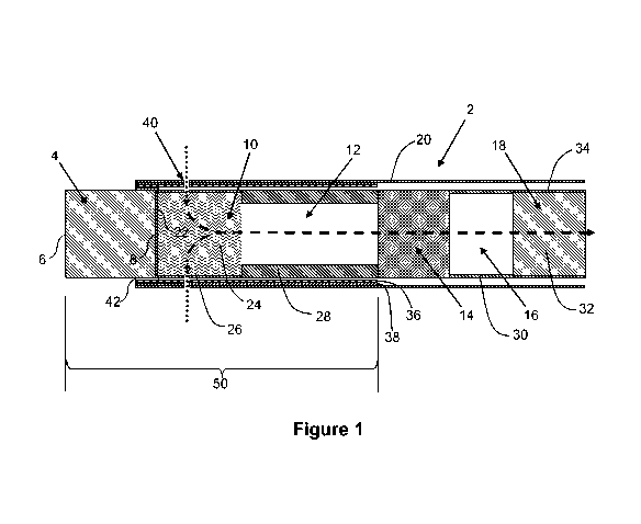
The smoking article 2 according to the first embodiment of the invention shown
in Figure 1
comprises a blind combustible heat source 4 having a front face 6 and an
opposed rear face 8,
an aerosol-forming substrate 10, a transfer element 12, an aerosol-cooling
element 14, a spacer
element 16 and a mouthpiece 18 in abutting coaxial alignment.
The blind combustible heat source 4 is a blind carbonaceous combustible heat
source and
is located at the distal end of the smoking article 2. As shown in Figure 1, a
non-combustible
substantially air impermeable barrier 22 in the form of a disc of aluminium
foil is provided
between the rear face 8 of the blind combustible heat source 4 and the aerosol-
forming
substrate 10. The barrier 22 is applied to the rear face 8 of the blind
combustible heat source 4
by pressing the disc of aluminium foil onto the rear face 8 of the blind
combustible heat source 4
and abuts the rear face 8 of the combustible carbonaceous heat source 4 and
the aerosol-
forming substrate 10.
In other embodiments of the invention (not shown), the non-combustible
substantially air
impermeable barrier 22 between the rear face 8 of the blind combustible heat
source 4 and the
aerosol-forming substrate 10 may be omitted.
The aerosol-forming substrate 10 is located immediately downstream of the
barrier 22
applied to the rear face 8 of the blind combustible heat source 4. The aerosol-
forming substrate
10 comprises a cylindrical plug of homogenised tobacco-based material 24
including an aerosol
former such as, for example, glycerine, wrapped in plug wrap 26.
The transfer element 12 is located immediately downstream of the aerosol-
forming
substrate 10 and comprises a cylindrical open-ended hollow cellulose acetate
tube 28.
The aerosol-cooling element 14 is located immediately downstream of the
transfer
element 12 and comprises a gathered sheet of biodegradable polymeric material
such as, for
example, polylactic acid.
CA 02998256 2018-03-09
WO 2017/042297
PCT/EP2016/071234
- 20 -
The spacer element 16 is located immediately downstream of the aerosol-cooling
element
14 and comprises a cylindrical open-ended hollow paper or cardboard tube 30.
The mouthpiece 18 is located immediately downstream of the spacer element 16.
As
shown in Figure 1, the mouthpiece 18 is located at the proximal end of the
smoking article 2 and
comprises a cylindrical plug of suitable filtration material 32 such as, for
example, cellulose
acetate tow of very low filtration efficiency, wrapped in filter plug wrap 34.
As shown in Figure 1, the smoking article 2 further comprises a single heat-
conducting
element 36 of suitable material such as, for example, aluminium foil,
overlying a rear portion of
the blind combustible heat source 4, the entire length of the aerosol-forming
substrate 10 and
the entire length of the transfer element 12.
In other embodiments of the invention (not shown), the transfer element 12 may
extend
beyond the single heat-conducting element 36 in the downstream direction. That
is the single
heat-conducting element 36 may overlie only a front portion of the transfer
element 12. In other
embodiments of the invention (not shown), the single heat-conducting element
36 may not
overlie any of the transfer element 12.
In further embodiments of the invention (not shown), the aerosol-forming
substrate 10
may extend beyond the single heat-conducting element 36 in the downstream
direction. That is
the single-heat-conducting element 36 may overlie only a front portion of the
aerosol-forming
substrate 10.
The single heat-conducting element 36 is circumscribed by a wrapper 38 of heat-
insulative sheet material such as, for example, cigarette paper, of low air
permeability, which is
wrapped around the aerosol-forming substrate 10, transfer element 12 and a
rear portion of the
blind combustible heat source 4 to form a multi-segment component 50 of the
smoking article 2.
The aerosol-cooling element 14, spacer element 16 and mouthpiece 18 may be
circumscribed by a further wrapper (not shown) to form a second multi-segment
component
(also not shown) downstream of the multi-segment component 50. In such
examples, the multi-
segment component 50 and the second multi-segment component may be held
together by the
outer wrapper 20 or by an additional wrapper or band of tipping paper.
Alternatively, the
aerosol-cooling element 14, spacer element 16 and mouthpiece 18 may be
individual segments
that are held together and connected to the multi-segment component 50 by the
outer wrapper
20.
In other embodiments (not shown) the wrapper 38 may extend downstream of the
transfer
element 12 to circumscribe other components of the smoking article 2, such as
the aerosol-
cooling element and the spacer element 16 which are then incorporated into the
multi-segment
component. The mouthpiece 18 may then be connected at the downstream end of
the multi-
CA 02998256 2018-03-09
WO 2017/042297
PCT/EP2016/071234
-21 -
segment component by outer wrapper 20, or by an additional wrapper or a band
of tipping
paper (not shown).
In the smoking article 2 according to the first embodiment of the invention
shown in Figure
1, the single heat-conducting element 36 and the wrapper 38 extend to
approximately the same
position on the blind combustible heat source 4 in the upstream direction and
in the downstream
direction, such that the upstream ends of the single heat-conducting element
36 and the
wrapper 38 are substantially aligned over the blind combustible heat source 4
and such that the
downstream ends of the single heat-conducting element 36 and the wrapper 38
are
substantially aligned at the downstream end of the transfer element 12.
However, it will be appreciated that in other embodiments of the invention
(not shown), the
wrapper 38 may extend beyond the single heat-conducting element 36 in the
upstream
direction.
The smoking article 2 according to the first embodiment of the invention
comprises one or
more first air inlets 38 around the periphery of the aerosol-forming substrate
10.
As shown in Figure 1, a circumferential arrangement of first air inlets 40 is
provided in the
plug wrap 26 of the aerosol-forming substrate 10, the wrapper 38 and the
single heat-
conducting element 36 to admit cool air (shown by dotted arrows in Figure 1)
into the aerosol-
forming substrate 10.
Also shown in Figure 1 is an intumescent layer 42 positioned between the
combustible
heat source 4 and the wrapper 38. In this example, the intumescent layer 42 is
arranged on an
inner surface of the heat-conducting element 36 such that it is in direct
contact with the
combustible heat source 4. In other examples (not shown), the intumescent
layer 42 may be in
contact with the combustible heat source 4 indirectly, for example via the
heat-conducting
element 36. The intumescent layer 42 circumscribes the combustible heat source
4 and is
arranged to expand in response to heat from the combustible heat source 4. The
intumescent
layer 42 is formed from an intumescent inorganic glue. Suitable intumescent
inorganic glues
include sodium silicate glues, such as those available from PQ Corporation of
Malvern,
Pennsylvania, US.
As described below in relation to Figures 2A and 2B, the combustible heat
source may
comprise one or more shaped recesses on its outer surface which are filled or
partially filled by
the intumescent inorganic glue of the intumescent layer 42 to improve
retention of the
combustible heat source 4 within the wrapper 38.
The smoking article may further comprise a band of tipping paper (not shown)
circumscribing a downstream end portion of the outer wrapper 20.
The multi-segment component 50 may further comprise a removable cap (not
shown) at
its distal end and directly adjacent to the heat source 4. For example, the
removable cap may
CA 02998256 2018-03-09
WO 2017/042297
PCT/EP2016/071234
- 22 -
comprise a central portion including a desiccant, such as glycerine, to absorb
moisture as
compared to the heat source, which is wrapped in a portion of one or both of
the outer wrapper
20 and the wrapper 38 and connected to the rest of that wrapper along a line
of weakness
comprising a plurality of perforations in the wrapper that circumscribe the
smoking article 2. In
such examples, to use the smoking article, the user removes the removable cap
by transversely
compressing the cap by pinching it between thumb and finger. By compressing
the cap,
sufficient force is provided to the line of weakness to locally break the
wrapper by which the cap
is connected. The user then removes the cap by twisting the cap to break the
remaining portion
of the line of weakness. When the cap is removed the heat source is partially
exposed which
enables the user to light the smoking article.
In use, a user ignites the blind combustible heat source 4 of the smoking
article 2
according to the first embodiment of the invention and then draws on the
mouthpiece 18. When
a user draws on the mouthpiece 18, air (shown by dotted arrows in Figures 1)
is drawn into the
aerosol-forming substrate 10 of the smoking article 2 through the air inlets
40.
The front portion of the aerosol-forming substrate 10 is heated by conduction
through the
rear face 8 of the blind combustible heat source 4 and the barrier 22.
The heating of the aerosol-forming substrate 10 by conduction releases
glycerine and
other volatile and semi-volatile compounds from the plug of homogenised
tobacco-based
material 24. The compounds released from the aerosol-forming substrate 10 form
an aerosol
that is entrained in the air drawn into the aerosol-forming substrate 10 of
the smoking article 2
through the first air inlets 40 as it flows through the aerosol-forming
substrate 10. The drawn air
and entrained aerosol (shown by dashed arrows in Figures 1 and 2) pass
downstream through
the transfer element 12, aerosol-cooling element 14 and spacer element 16,
where they cool
and condense. The cooled drawn air and entrained aerosol pass downstream
through the
mouthpiece 18 and are delivered to the user through the proximal end of the
smoking article 2
according to the first embodiment of the invention. The non-combustible
substantially air
impermeable barrier 22 on the rear face 8 of the blind combustible heat source
4 isolates the
blind combustible heat source 4 from air drawn through the smoking article 2
such that, in use,
air drawn through the smoking article 2 does not come into direct contact with
the blind
combustible heat source 4.
In use, the single heat-conducting element 36 retains heat within the smoking
article 2 to
help maintain the temperature of the aerosol-forming substrate 10 and so
facilitate continued
and enhanced aerosol delivery. In addition, the single heat-conducting element
36 transfers
heat along the aerosol-forming substrate 10 so that heat is dispersed through
a larger volume of
the aerosol-forming substrate 10. This helps to provide a more consistent puff-
by-puff aerosol
delivery.
CA 02998256 2018-03-09
WO 2017/042297
PCT/EP2016/071234
- 23 -
During heating of the intumescent layer 42 by the combustible heat source 4,
water in the
intumescent inorganic glue is vapourised to produce air bubbles, thus
expanding or foaming the
glue. As the intumescent layer 42 is formed from an intumescent inorganic
glue, there is
substantially no loss of material or volume from the intumescent layer 42
during combustion of
the combustible heat source 4. The expanded intumescent layer 42 ensures that
the
combustible heat source 4 remains tightly held in the wrapper 38 during use,
even if one or both
of the heat-conducting element 36 and the wrapper 38 expand due to their own
thermal
expansion characteristics. In addition to ensuring that the combustible heat
source 4 remains
tightly held within the wrapper 38, the expanded intumescent layer 42 also
forms a barrier
around the combustible heat source 4 to reduce or prevent bypass of combustion
gases around
the outside of the combustible heat source 4. In this example, the intumescent
layer 42 is in
direct contact with the outer surface of the combustible heat source 4.
Consequently, the
expanded intumescent layer 42 can compensate for the surface roughness of the
combustible
heat source, or for geometry defects of the combustible heat source 4, to
reduce the bypass of
combustion gases around the heat source 4. Consequently, the RTD of the
smoking article 2
may be maintained. Additionally, since the combustible heat source 4 is a
blind combustible
heat source, the expanded intumescent layer 42 ensures that substantially all
of the airflow
during use enters the aerosol-forming substrate 10 through the air inlets 40,
for desirable
aerosol properties.
The intumescent layer 42 has an unexpanded thickness of from about 0.01 mm to
about
0.1 mm and has an expansion ratio of from about 1.5:1 to about 5:1.
Consequently, the
intumescent layer 42 can be expanded without substantially affecting the
external appearance
of the smoking article 2.
Figures 2A and 2B show a combustible heat source 200 for a multi-segment
component
according to the present invention. The combustible heat source 200 is
substantially cylindrical
and has an outer diameter, as indicated by dimension D1 in Figures 2A and 2B,
that is
substantially constant along the entire length of the combustible heat source
200. The
combustible heat source 200 has a front face 206 and an opposed rear face 208
and a plurality
of shaped recesses on its outer surface 202 formed from a plurality of
circumferentially spaced
apart longitudinal grooves 210. The longitudinal grooves 210 extend from the
front face 206
towards the rear face 208 but terminate upstream of the rear face 208 to
define a rear portion
204 having a substantially constant, circular cross-section and a
substantially continuous outer
surface. The longitudinal grooves 210 terminate at the upstream end of the
rear portion 204.
The rear portion 204 extends from the downstream end of the longitudinal
grooves 210 to the
rear face 208 of the combustible heat source 200 and has a length as indicated
by dimension
H1. In this example, the length of the rear portion is less than about 3mm.
CA 02998256 2018-03-09
WO 2017/042297
PCT/EP2016/071234
- 24 -
Since the grooves 210 do not extend to the rear face 208 of the combustible
heat source
200, during use, the rear portion 204 may form a barrier to reduce the bypass
of combustion
gases around heat source in the downstream direction. The rear portion may
define the
maximum outer diameter of the combustible heat source. Such an arrangement may
improve
ease of manufacture by making it easier to wrap the wrapper around the heat
source. It may
also improve conductive heat transfer from the heat source to the wrapper.
This may be
particularly advantageous in examples of multi-segment component in which the
wrapper
comprises a heat-conducting layer for transferring thermal energy from the
combustible heat
source to the aerosol-forming substrate
During manufacture of a multi-segment component incorporating the combustible
heat
source 200, the longitudinal grooves 210 may be filled or partially filled
with a glue to improve
retention of the combustible heat source 200 within a wrapper of the multi-
segment component.
As the grooves 210 are aligned with the longitudinal axis of the combustible
heat source 200,
when the heat source 200 is assembled in an aerosol generating article, such
as smoking
article 2 discussed above in relation to Figure 1, the longitudinal grooves
210 will be parallel to
the upstream direction of the aerosol generating article and thus parallel to
the direction in
which undesirable movement of the combustible heat source 200 may occur. With
this
arrangement, the retention force applied by the glue to the combustible heat
source 200 is
increased by the orientation of the longitudinal grooves 210. This may help to
ensure correct
positioning of the combustible heat source within the aerosol generating
article during use and,
thus, desirable aerosol properties.
In this example, the longitudinal grooves 210 are evenly spaced around the
circumference
of the combustible heat source 200 and are substantially the same length. In
other examples
(not shown) the longitudinal grooves 210 may be unevenly spaced and one or
more of the
longitudinal grooves 210 may be shorter or longer than the other longitudinal
grooves 210.
The longitudinal grooves 210 each have a bottom, or trough, 212 which is
connected to
the outer surface 202 of the combustible heat source 200 by radially outer
edges 214 of the
groove 210. The outer edges 214 are curved with a radius of curvature of at
least about 15 %
of the depth D2 of its respective groove. Preferably the radius of curvature
is at least about
0.05 mm. This may advantageously result in improved filling of the grooves 210
during
manufacture of a multi-segment component. It may also result in a reduction in
the visibility of
the at least one recess through a wrapper of the multi-segment component and
reduce the risk
of damage to the wrapper caused by the radially outer edges of the at least
one recess during
wrapping. Furthermore, with this arrangement, the radially outer edges of the
combustible heat
source are less likely to be damaged or break off during manufacture, reducing
the amount of
dust, such as carbon dust, generated during manufacture.
CA 02998256 2018-03-09
WO 2017/042297
PCT/EP2016/071234
- 25 -
The longitudinal grooves 210 have a depth, as indicated by dimension D2 in
Figures 2A
and 2B, that is defined by the difference between the radius of the outer
surface 202 of the
combustible heat source, as indicated by dimension R1 in Figure 2B, and the
radius of the
bottom 212 of each groove 210, as indicated by dimension R2 in Figure 2B. In
this example,
the depth of the grooves 210 is less than about 10 percent of the outer
diameter, D1, of the
combustible heat source 200. This has the advantage that the mass of the heat
source 200,
and consequently its heating performance, is substantially unaffected by the
presence of the
longitudinal grooves 210. Additionally, the time required for any glue filling
the longitudinal
grooves 210 to dry after its application may be reduced, improving
manufacturability. In certain
examples, the depth of the longitudinal grooves 210 is between 0.05 mm and
about 0.4 mm.
In this example, the depth of each of the longitudinal grooves 210 is
substantially constant
along its length. In other examples (not shown) the depth of one or more
grooves decreases
towards its downstream end. This has the advantage that the retention of the
heat source can
be further improved as the glue may act as a wedge to resist upstream movement
of the heat
source relative to the wrapper. It has also been found to result in improved
filling of the grooves
210 by the glue, since the glue more easily flows across the bottom surface
212 of each groove
210.
Figures 3A and 3B are schematic illustrations of a manufacturing process for
making the
multi-segment component of Figure 1. In Figures 3A and 3B, the aerosol-forming
substrate 10
and transfer element 12 are omitted for clarity.
In the manufacturing process, a heat-conducting sheet 336 formed from a
combustion-
resistant heat-conductive material, such as aluminium, is placed onto a web
338 of wrapper
material, such as cigarette paper. An intumescent inorganic glue 342 is then
deposited onto the
heat-conducting sheet 336 using a roller and a combustible heat source 304
placed on top.
Suitable intumescent inorganic glues include sodium silicate glues, such as
the "Crystal" range
of sodium silicate liquid glues available from PQ Corporation of Malvern,
Pennsylvania, US.
As shown in Figure 3B, the paper web 338 is then pressed against and wrapped
into a
cylindrical shape around the combustible heat source 304 to form a continuous
tube. During
this wrapping step, the intumescent inorganic glue 342 is spread over the
outer surface of the
combustible heat source 304 to form an intumescent layer. The intumescent
inorganic glue 342
is also forced into the longitudinal grooves 310 on the outer surface of the
combustible heat
source 304 and to structurally bind the combustible heat source 304 to the
intumescent layer.
The continuous tube formed by the web 338 is then cut adjacent to the front
end of each
combustible heat source 304 to form individual rod-shaped multi-segment
components.
Other methods are possible. For example, other techniques may be used to apply
the
glue to the wrapper for example spreading or spraying, using a glue gun, or
rotogravure or other
CA 02998256 2018-03-09
WO 2017/042297
PCT/EP2016/071234
- 26 -
printing technics. The glue may be applied to the combustible heat source. The
glue may be
applied to the wrapper and the combustible heat source.
Example 1
To form the intumescent layer, an inorganic sodium silicate glue having a
silicon dioxide
content of 28.5% to 30.0%, a sodium oxide content of 8.5% to 9.0%, and a molar
ratio of 3.3 to
3.5 is applied between the combustible heat source and the wrapper using the
method
described above in relation to Figures 3A and 3B.
Example 2
To form the intumescent layer, an inorganic sodium silicate glue having a
silicon dioxide
content of about 29.9%, a sodium oxide content of about 9.4%, and a molar
ratio of about 3.3 is
applied between the combustible heat source and the wrapper using the method
described
above in relation to Figures 3A and 3B.
Example 3
To form the intumescent layer, an inorganic sodium silicate glue having a
silicon dioxide
content of 33.1% to 34.1%, a sodium oxide content of 12.0% to 13.0%, a molar
ratio of 2.6 to
2.9 and a dry solids content of 45.1% to 47.1% is applied between the
combustible heat source
and the wrapper using the method described above in relation to Figures 3A and
3B.
Example 4
To form the intumescent layer, an inorganic sodium silicate glue having a
silicon dioxide
content of 29.0% to 30.5%, a sodium oxide content of 8.5% to 9.0%, and a molar
ratio of 2.0 to
2.1 is applied between the combustible heat source and the wrapper using the
method
described above in relation to Figures 3A and 3B.
Example 5
To form the intumescent layer, an inorganic sodium silicate glue having a
silicon dioxide
content of 30% to 31%, a sodium oxide content of 11.4% to 12.4%, and a molar
ratio of 2.6 to
2.7 is applied between the combustible heat source and the wrapper using the
method
described above in relation to Figures 3A and 3B.
The specific embodiments and examples described above illustrate but do not
limit the
invention. It is to be understood that other embodiments of the invention may
be made and the
specific embodiments and examples described herein are not exhaustive.