Note: Descriptions are shown in the official language in which they were submitted.
DESCRIPTION
(1) Title of the Invention
TEST DEVICE FOR DETERMINING THREE-DIMENSIONAL CONSOLIDATION PROPERTIES OF
SOILS
(2) Background of the invention
Standard test methods for determining one-dimensional consolidation properties
of soils using
incremental loading in accordance with ASTM D2435, or AASHTO 216 (2012) and of
those of other
international and organizations, do not accurately predict the consolidation
properties of soils, such as
values of vertical settlement, coefficients of consolidation in horizontal (CO
and vertical directions (cv), and
modulus of elasticity (E); because fixed ring used in these tests do not allow
horizontal displacement and
dissipation of excess pore-water pressures in horizontal direction, whereas,
in field, under application of a
vertical load, both horizontal and vertical settlements occur along with
dissipation of excess pore-water
pressures in both vertical and horizontal
directions. To overcome this more than 100 year old problem, the inventor (Dr.
Ramesh Chandra Gupta,
Ph. D., P.E.) has invented a test device for determining three-dimensional
consolidation properties of
soils, using a flexible ring which permits development of horizontal and
vertical displacements, and
dissipation of excess pore-water pressures in both horizontal and vertical
directions, along with increased
lateral resistance as takes place in field at any depth in a soil deposit when
a vertical load is applied at the
surface.
The flexible ring (110) consists of filter fabric (113) around the soil
specimen (104), rubber membrane
(111) around the filter fabric (113), circular segmental metal plates (117)
around the membrane (111) and
elastomeric rubber bands (109) or spring loaded jacket around the segmental
plates (117) to allow
horizontal and vertical displacements, dissipation of excess pore-water
pressures in horizontal and
vertical directions, and increased lateral resistance with each increment of
vertical load. Therefore, new
test device, which simulates field condition, shall allow accurate
determination of three-dimensional
consolidation properties of soils (such as vertical and horizontal
settlements, coefficients of consolidation
(cv and chi) in horizontal and vertical directions, including three-
dimensional coefficient of consolidation (c3_
o) and modulus of elasticity.
For this new test device, conventional incremental consolidation frame shall
be used for applying vertical
load increments, each to be maintained for 24 hours for allowing dissipation
of excess pore-water
pressures. Triaxial type chamber and loading system shall also be used after
suitably modifying to adapt
new 3-D consolidation device. With triaxial type chamber system or other
sealed metal or acrylic systems,
some modifications shall also be done to adapt to Incremental consolidation
frame in place of triaxial
loading system, to compare which is more suitable of these two loading systems
for three-dimensional
consolidation tests.
(7) Brief Summary of the Invention
This invention introduces a test device for determining three-dimensional
consolidation properties of soils
using a flexible ring. The flexible ring (110) consists of filter fabric (113)
around the soil specimen (104),
rubber membrane (111)around the filter fabric (113), circular segmental metal
plates (117) around the
membrane (111)and elastomeric rubber bands or rings (109) or spring loaded
jacket around the
segmental plates (117) to allow horizontal and vertical displacements,
dissipation of excess pore-water
pressures in horizontal and vertical directions, and increase in lateral
resistance with each increment of
1
CA 2998340 2019-11-11
vertical load. Therefore, new test device, which simulates field condition,
shall allow accurate
determination of three-dimensional consolidation properties of soils
(including vertical and horizontal
settlements, coefficients of consolidation (cv and chi) in horizontal and
vertical directions and modulus of
elasticity.
This is new invention for a test device to determine three-dimensional
consolidation properties of soils. So
far only one-dimensional consolidation properties have been determined using
ASTM D2435 and
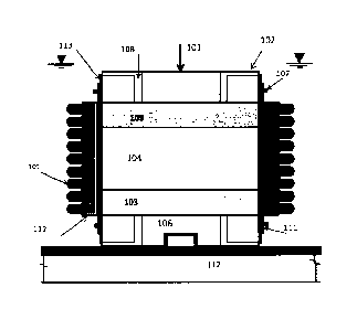
AASHTO 216. One-dimensional consolidation devices (prior art), as shown in
FIG. 1, do not simulate field
conditions and therefore do not provide accurate values of consolidation
properties.
Three-dimensional consolidation device consists of a flexible ring (110)
instead of a rigid ring (105) as
used for one-dimensional consolidation test. The flexible ring (110) consists
of about 10 stainless steel (or
other non-corrodible metal) segment plates (117), circular arch in shape for
2.87" (72.9 mm) diameter
specimen as shown in FIG. 2 through FIG. 5. The thickness of plates (117) may
vary between 1/16" and
3/8" (1.6 mm and 9.53 mm) in thickness. Thicker segmental plates (117) will
not bend under the force
exerted by elastomeric rubber bands or rings (109) and in this respect may
have some advantage over
thinner plates. When vertical load is applied on soil specimen, vertical and
horizontal displacement shall
occur in the soil specimen, and the elastomeric rubber bands around the
flexible ring shall expand to
allow the horizontal displacement to occur.
FIG. 2 shows the schematic detail of a test when dissipation of excess pore
water pressures can take
place only in vertical direction, but unlike one-dimensional consolidation
test, displacements both in
vertical and horizontal (radial) directions can take place simultaneously when
the vertical load is applied.
This test shall permit the determination of coefficient of consolidation in
vertical direction.
FIG. 3 shows the schematic detail of a test when dissipation of excess pore
water pressures can take
place only in horizontal (radial directions) direction, but unlike one-
dimensional consolidation test,
displacements both in vertical and horizontal (radial) directions can take
place simultaneously when the
vertical load (101) is applied. This test shall permit the determination of
coefficient of consolidation in
horizontal direction. For this test, a filter fabric (113) is wrapped around
the soil specimen. A thick rubber
membrane (111) is then installed around the filter fabric (113). It may be
noted that the filter fabric (113)
extends both below and top of the rubber membrane (111) to allow dissipation
of excess pore-water
pressures. Porous discs (103) are not required for this test as dissipation of
pore-water pressures in
vertical direction are not allowed in this test.
FIG. 4 shows the schematic detail of a test when dissipation of excess pore
water pressures can take
place both in vertical and horizontal (radial) directions, but unlike one-
dimensional consolidation test,
displacements both in vertical and horizontal (radial) directions can take
place simultaneously when the
vertical load (101) is applied. This test shall permit the determination of
three-dimensional coefficient of
consolidation. In this test, three-dimensional consolidation shall take place
exactly the same way as will
take place in insitu conditions in the field. As shown in FIG. 4, porous discs
(103) are used to allow
dissipation of pore-water pressures in vertical direction and filter fabric
(113) around soil specimen (104)
is used to allow dissipation of excess pore-water pressures in horizontal
(radial) direction.
The specimens from various depths of a cohesive deposit are obtained by use of
Shelby tubes or other
type of samplers. The sample shall be extracted from the samplers, in the same
manner as is used to
extract samples for one-dimensional consolidation test. For the three-
dimensional consolidation tests
using flexible ring, there is no need of shaping the specimen to push into
fixed ring as is required for the
one-dimensional consolidation test. After cutting to the required lengths and
leveling the ends of the
specimen, the specimen for three-dimensional consolidation test, shall be
placed on the porous disc/base
plate and then capped by top porous disc/loading head. Using a membrane
expander, filter consisting of
2
CA 2998340 2019-11-11
elastic filter fabric (113) in the form a cylinder shall be installed around
the soil specimen as is shown in
FIG. 3 and FIG. 4. Using membrane expander, a thick rubber membrane (111)
shall be installed around
the filter fabric/soil specimen as shown in FIG. 3 and FIG. 4. A thicker
rubber membrane (111) which can
be installed using a membrane expander or other appropriate device, shall have
some advantage over
thinner membrane as a thick rubber membrane shall keep cylindrical shape along
the joint space between
the segment plates. It may be noted that filter fabric (113) is not needed for
test which allows dissipation
of excess pore-water pressures in vertical direction only, as shown in FIG. 2.
Commercially available woven or non-woven filter fabric can also be used after
stitching it into a
cylindrical shape using a strip of elastic cloth. Filter fabric can also be
wrapped around the soil specimen
with about 1/2" (12.7 mm) overlap and maintained stretched or taut in place by
a 1" (25.4 mm) long
adhesive tape at the ends. This tape shall be removed after installation of
the rubber membrane around
the specimen. Stainless steel segment plates or non-corrodible metal segment
plates of thickness
generally varying between about 1/16" and 3/8" (1.59 and 9.53 mm) are
installed around the membrane,
using two half-circular brackets (114) as shown in FIG. 5(a) and FIG. 5(b).
The width of the bracket
plates (114) may generally vary between about 3/8" and 1" (9.53 mm and 25.4
mm). The thickness of
these brackets (114) can vary generally between about 3/32" and 3/8" (2.38 mm
and 9.53 mm).
Elastomeric rubber bands (109) of generally about between 1/16 and 3/16" (1.6
mm and 4.76 mm)
thickness are slipped on around the plates (117) at marked locations as shown
in FIG. 7. The width of
rubber bands can vary generally between about 1/8" and 1/2" (3.2 mm and 12.7
mm). The diameter of
elastomeric rubber rings with circular cross-section, when used in place of
bands, can vary generally
between about 1/16" and 3/8" (between 1.6 and 9.53 mm). Several threaded holes
at different heights of
the plates in addition to those shown in figures, shall also be provided to
install the brackets at different
heights. For example, as an alternative, after rubber bands or rings above the
bracket have already been
installed, another bracket can be installed near the bottom of the segmented
plates, thereafter, the
bracket at the middle of the segmented plates can be un-installed, and rubber
bands or rings are then
installed in the remaining space above the bracket.
The brackets are then un-installed. Remaining rubber bands or rings are
slipped on around the plates in
the space earlier covered by the brackets, as shown in FIG. 8. The expandable
or flexible ring (110) has
thus been installed around the soil specimen. Since segmental circular plates
(117) are resting against
the top and bottom porous discs or base plate and loading head, initially the
lateral load exerted by rubber
bands acts on the porous discs and very little, if any, directly on the soil
specimen in the beginning of the
test. When specimen begins to undergo lateral displacement or lateral
expansion during the test, the
rubber bands around the segmental plates shall stretch and exert pressure on
the segmental plates
thereby on the surface of the soil specimen all along its height and shall
help in maintaining the uniform
diameter through its height during the test; the plates are then not in
contact with porous discs and so
rubber bands exert lateral pressure on the specimen. As many rubber bands as
needed to maintain
uniform diameter of cylindrical specimen and also to resist lateral pressures
proportional to the applied
vertical load during the test, shall be used. The inside surface of segment
plates shall be lubricated to
reduce friction between rubber membrane around soil specimen and the plates.
The function of
segmental stainless-steel plates is to uniformly distribute the lateral load
applied by rubber bands on the
soil specimen.
Alternatively, the lubricated segment plates can be assembled around soil
specimen by use of about
between 1/2" and 1" (12.7 mm and 25.4 mm) wide leather or nylon or polyester
or polypropylene Velcro
straps. First, segment plates are fastened to Velcro strap using 5-44 or M-3
screws (116) as shown in
FIG. 9 (other screw sizes may be used along with appropriate female threads in
segment plates). Then
the assembled plates are wrapped around the soil specimen and maintained in
position by Velcro strap
as shown in FIG. 10. The rubber bands of thickness of generally between about
1/16" and 3/16" (1.59 mm
3
CA 2998340 2019-11-11
and 4.76 mm) are slipped on around the plates as shown in FIG. 11. The screws
are unthreaded to
remove the straps. The remaining rubber bands are then slipped on around the
plates in the space earlier
occupied by the Velcro straps, as shown in FIG. 12. The flexible ring has now
been installed around the
soil specimen. The leather or nylon Velcro straps can also be installed near
the bottom in addition shown
one shown at middle of the height in the figures as considered necessary to
properly install the rubber
bands or rings.
Sizes of segment plates, half brackets and rubber bands shown in FIG. 2
through FIG. 9 and described in
the text above are based on soil specimen diameter of 2.87" (72.9 mm) in
diameter. Diameter of soil
specimen is also dependent on inside diameter of Shelby tubes or other type of
samplers used for
extracting the samples from a cohesive deposit. Inside diameter of Shelby
tubes as per ASTM standards
are 1.905" (48.42 mm), 2.87" (72.9 mm) and 4.76" (120.9 mm). The diameter of
circular arch shaped
segment plates and two half brackets shall depend on the diameter soil
specimen. Number of segment
plates shall be generally about 8, 10 and 16 for soil specimen of 1.905"
(48.42 mm), 2.87" (72.9 mm) and
4.76" (120.9 mm), respectively. For other specimen sizes, special design
detail shall be used.
FIG. 13 shows the calibration device. In FIG. 14, the flexible ring (110) has
been mounted around the
calibration device for performing calibration of flexible ring to determine
the hydraulic pressure or water
overhead above calibration device versus lateral strain relationship and
thereby to determine combined
modulus of elasticity of filter fabric, rubber membrane and elastomeric rubber
membrane.
The details as described here-in for flexible ring including its installation
techniques, instrumentation and
calibration device may be revised in future, when there is a need to do so for
improving the accuracy and
workability of the test device for determination of three-dimensional
consolidation properties of soils.
In FIG. 15 and FIG. 16, the detail shows 3-D device assembly (157) placed in a
triaxial chamber with
triaxial type loading system and incremental loading system, respectively.
FIG. 17 shows the LVDT or
strain gage (151) mounted U-Frame device (150) resting on frictionless
bearings (152) to allow radial
expansion of the specimen during the test.
(8) Brief Description of the several views of the drawing
FIG. 1 describes the test device for determining one-dimensional consolidation
properties of soils
(PRIOR ART). FIG. 2 shows three-dimensional test device permitting both
horizontal and lateral
displacement but allowing dissipation of excess pore-water pressures only
vertical direction. FIG. 3 shows
three-dimensional test device permitting both horizontal and lateral
displacement but allowing dissipation
of excess pore-water pressures only horizontal (radial) direction. FIG. 4
shows three- dimensional
consolidation device permitting both horizontal and lateral displacement and
also allowing dissipation of
excess pore-water pressures both horizontal and vertical directions.
FIG. 5 (a) and FIG. 5(b) show schematic plan view detail of installing
circular segment plates (117) around
the soil specimen using two half-circular brackets (114). FIG. 6 shows
schematic elevation view detail of
installing circular segment plates (117) around the soil specimen using two
half-circular brackets (114).
FIG. 7 shows the elevation view when elastomeric rubber bands (109) have been
slipped above and
below the two half-circular brackets (114). FIG. 8 shows the elevation view
when both half-circular
brackets (114) have been un-installed and remaining rubber bands (109) in the
area previously occupied
by brackets have been installed.
FIG. 9 shows the installation of circular segment plates (117) using leather
or nylon Velcro straps (121),
instead of using two half-circular brackets. FIG. 10 shows the elevation view
when elastomeric rubber
bands have been slipped above and/or below and above the Velcro straps. FIG.
11 shows the elevation
4
CA 2998340 2019-11-11
view when Velcro strap has been un-installed and remaining rubber bands in the
area previously
occupied by brackets have been installed. Thus, installation of flexible ring
using Velcro straps has been
completed.
FIG. 12(a) shows an elevation view of installation of the reservoir
cylindrical wall (122) made of stainless
steel or of Acrylic or Perspex. At the base, the reservoir cylindrical wall is
clamped to the table top using
a rubber gasket (123) for water tightness and appropriate size screws (124).
FIG. 12(b) shows another
detail of a reservoir for placing assembled 3-D device in it. In this case
reservoir cylindrical wall and
bottom plate consists either of metal or acrylic (125). When acrylic is used,
the acrylic wall and the bottom
shall be connected by weld-on plastic adhesive. In case of metal, normal weld
shall be used. FIG. 12(c)
shows that instead of weld, the acrylic or metal tube shall be screwed in the
base plate, when 3-D device
has already been assembled on base plate.
FIG. 12(d) shows a sealed chamber which can withstand lateral water pressure
at least up to 150 psi
(1034 kPa). For this chamber, first 3-D device (157) shall be assembled on the
metal base plate (129),
then the side metal wall (128) shall be installed and bolted to the base plate
as shown in this figure. The
0-ring or flat gasket (132) shall seal the base plate (129) and top plate
(126) to the cylindrical side walls.
Fig. 12 (e) shows another schematic detail of a sealed metal or acrylic
chamber. For this detail a thick
metal or acrylic cylindrical wall shall be used in which the holes can be
drilled as shown in this figure. The
long bolts (131) shall be inserted in the holes from the bottom and tightened
from the top when top plate
has been placed. Both bottom and top plates shall be made watertight by
seating a flat gasket or 0-
Rings/Ring in between the plates and the side wall.
FIG. 13 shows the calibration device, which consists of porous metal tube
(144) covered by a rubber
membrane (141). The tube is connected to a reservoir (134) which can be raised
or lowered on a metal
stand (135). In FIG. 14, the flexible ring (110) has been mounted around the
calibration device for
performing calibration of flexible ring to determine the hydraulic pressure
versus lateral strain relationship
and thereby to determine combined modulus of elasticity of filter fabric
(113), rubber membrane (109) and
elastomeric rubber membrane (111).
FIG. 15 shows schematic detail for assembling a 3-D consolidation test device
on base plate then
covered by a triaxial type chamber and also connected to control panel and
load frame to perform the
test.
FIG. 16 shows schematic detail for assembling a 3-D consolidation test device
on base plate then
covered by a triaxial type chamber and also connected to control panel and
incremental loading
device/frame to perform the test.
FIG. 17 shows the frictionless U-Frame device (150) to mount LVDT or strain
gage (151) to measure
radial expansion of specimen.
Figure and Table Captions are given below:
FIG. 1: Schematic detail of test device for performing one-dimensional
consolidation test (PRIOR ART).
FIG. 2: Schematic Detail of three-dimensional test device for permitting
dissipation of excess pore-water
pressure in vertical direction only, but allowing vertical and horizontal
displacement of the soil specimen to
take place.
CA 2998340 2019-11-11
FIG. 3: Schematic Detail of three-dimensional test device for permitting
dissipation of excess pore-water
pressure in horizontal direction only, but allowing vertical and horizontal
displacements of the soil
specimen to take place.
FIG. 4: Schematic detail of three-dimensional consolidation test device for
permitting dissipation of excess
pore-water pressure in vertical and horizontal directions, and also allowing
vertical and horizontal
displacements of the soil specimen to take place.
FIG. 5 (a) and (b): Layout plan for installation of circular segment plates
(117) around soil specimen using
two half-circular brackets (114).
FIG. 6: Elevation view for installation of circular segment plates (117)
around soil specimen (104) using
two half-circular brackets (114).
FIG. 7: Elevation view for installation of rubber bands (109) around circular
segment plates (117) in the
space above and/or below half-circular brackets (114).
FIG. 8: Elevation view for installation of additional rubber bands (109)
around circular segment plates in
the remaining space after un-installing half-circular brackets.
FIG. 9: Elevation view for installation of circular segment plates around soil
specimen using leather or
nylon Velcro strap (121).
FIG. 10: Elevation view for installation of rubber bands around circular
segment plates in the space above
and/or below Velcro strap (121).
FIG. 11: Elevation view for installation of additional rubber bands around
circular segment plates after un-
installing Velcro strap.
FIG. 12:(a) Elevation view of three-dimensional consolidation test device
after installation of cylindrical
reservoir wall and then filling water in the reservoir, (b) open reservoir
consisting of acrylic or metal wall
and bottom welded together, (c) open reservoir consisting of metal or acrylic
wall and bottom threaded
together, and (d) water tight metal chamber/reservoir with separate bolts at
bottom and top to seal plates
to cylindrical side wall for application of lateral pressure in the chamber,
(e) water tight metal or acrylic
chamber/reservoir with long bolts inside holes in a thick cylindrical wall for
sealing bottom and top plates
to cylindrical side wall for application of lateral pressure in the chamber.
FIG. 13: Elevation view of calibration device.
FIG. 14: Elevation view of the calibration device after installation of
flexible ring for performing its
calibration.
FIG. 15: Sectional elevation of 3-D consolidation device setup with triaxial
type loading system and water
chamber with control panel to apply lateral pressure on soil specimen.
FIG. 16: Sectional elevation of 3-D consolidation device setup with
incremental consolidation loading
system and water chamber with control panel to apply lateral pressure on soil
specimen.
FIG. 17: Frictionless U-Frame for mounting LVDT or strain Gage to measure
radial expansion of the
sample.
Table 1: Form for entering data to calibrate the calibration device
6
CA 2998340 2019-11-11
Table 2: Form for entering data to calibrate the flexible ring
(9) Detailed Description of the invention
Detailed description of the invention has been explained below in Sections (a)
though
(9).
(a) Standard Test Methods and Their Limitations
The standard test method for one-dimensional consolidation properties of soils
using incremental loading
is described in ASTM Designation: D2435/D2435M-11 and in AASHTO 216.
International and national
organizations of several countries have their own standards for this test. The
test apparatus consists of a
rigid ring as shown in FIG. 1. The soil specimen is pushed in the ring to
perform the test.
When foundation loads are transmitted to cohesive subsoils, there is a
tendency for a volumetric strain
which in the case of saturated material is manifested in an increase in pore
water pressure. With sufficient
elapsed time, water flows out of the soil pores, permitting excess pore-water
pressure to dissipate. The
analysis of the volumetric strains which result, and the vertical settlements
accompanying them, is
simplified if we assume that such strains occur only in vertical direction.
Such an assumption may not be
unreasonable when the geometric and boundary conditions in the field are such
that vertical strains
dominate. For example, when dimensions,of the loaded area are large relative
to the thickness of the
compressible stratum and/or when the compressible material lies between two
stiffer soils whose
presence tends to reduce the magnitude of horizontal strains, an approximately
one-dimensional
compression of the soil will occur (Perloff and Baron, 1976).
However, generally, the above-mentioned example rarely occurs. In most cases,
three- dimensional
consolidation and settlements occur. Therefore, volumetric strains in soils
significantly depend on
displacements both in vertical and horizontal or radial directions. In those
cases, in which the thickness of
compressible strata is large related to the loaded area, the three-dimensional
nature of the problem shall
influence the magnitude and rate of settlement. Although numerical analysis
methods offer the prospect
of rational consideration of three-dimensional compression effects, they have
not proven useful in practice
(Winterkorn and Fang, 1990). In view of this, semi-empirical approaches have
been used for estimating
three-dimensional consolidation properties. The most commonly applied method
was developed by
Skempton and Bjerrum (1957), using two assumptions: (1) even though the
induced excess pore water
results from three-dimensional effects, the settlements are assumed as one-
dimensional, (2) to account
for three-dimensional consolidation, the vertical settlement at the centerline
is predicted as equal to
product of one-dimensional consolidation settlement times a factor A. The
value of A is estimated using a
chart, which has been plotted based on overconsolidation ratio and ratio of
the width of foundation with
thickness of consolidating stratum (HRB, 1973).
The coefficients of permeability and consolidation in horizontal direction has
been found to be much
greater than the coefficients of permeability and consolidation in vertical
direction of the same soil
deposits or stratum (Terzaghi et al. 1996). Depending on the anisotropy of the
soil deposits or presence
of very thin sand/silt layers in the soil deposits, the coefficients of
permeability and consolidation in
horizontal direction could be even 10 times greater than the coefficients of
permeability and consolidation
in vertical direction. In such cases, the method of Skempton and Bjerrum
(1957) using A factor cannot be
applied.
7
CA 2998340 2019-11-11
In view of the above, it is very important to develop a test which can
determine the three-dimensional
consolidation properties of soil deposits. To solve this problem of more than
100 years, the inventor has
invented a three-dimensional consolidation test device which permits the
dissipation of excess pore water
pressure both in vertical and horizontal (radial directions) directions along
with settlements occurring both
in vertical and horizontal (radial) directions.
(b)Three-dimensional consolidation test device
Three-dimensional consolidation device consists of a flexible ring (110)
instead of a rigid ring (105) as
used for one-dimensional consolidation test. The flexible ring consists of
about 10 stainless steel segment
plates (117), circular arch in shape for 2.87" (72.9 mm) diameter specimen as
shown in FIG. 2 through
FIG. 5. The thickness of plates (117) may vary generally between about 1/16"
and 3/8" (1.59 mm and
9.53 mm) in thickness. Thicker segmental plates (117) will not bend under the
force exerted by
elastomeric rubber bands (109) and in this respect may have some advantage
over thinner plates. When
vertical load (101) is applied on soil specimen (104), vertical and horizontal
displacement shall occur in
the soil specimen, the elastomeric rubber bands around the flexible ring shall
expand to allow the
horizontal displacement to occur uniformly.
FIG. 2 shows the schematic detail of a test when dissipation of excess pore
water pressures can take
place only in vertical direction, but unlike one-dimensional consolidation
test, displacements both in
vertical and horizontal (radial) directions can take place simultaneously when
the vertical load is applied.
This test shall permit the determination of coefficient of consolidation in
vertical direction.
FIG. 3 shows the schematic detail of a test when dissipation of excess pore
water pressures can take
place only in horizontal (radial directions) direction, but unlike one-
dimensional consolidation test,
displacements both in vertical and horizontal (radial) directions can take
place simultaneously when the
vertical load is applied. This test
shall permit the determination of coefficient of consolidation in horizontal
direction. For this test, a filter
fabric (113) is wrapped around the soil specimen. A thick rubber membrane
(111) is then installed around
the filter fabric. It may be noted that the filter fabric extends both below
and top of the rubber membrane
to allow dissipation of pore water pressures. Porous discs (103) are not
required for this test as
dissipation of pore-water pressures in vertical direction is not allowed in
this test.
FIG. 4 shows the schematic detail of a test when dissipation of excess pore
water pressures can take
place both in vertical and horizontal (radial) directions, but unlike one-
dimensional consolidation test,
displacements both in vertical and horizontal (radial) directions can also
take place simultaneously when
the vertical load is applied. This test shall permit the determination of
three-dimensional coefficient of
consolidation. In this test, three-dimensional consolidation shall take place
exactly the same way as will
take place in insitu conditions in the field. As shown in FIG. 4, porous discs
are used to allow dissipation
of pore-water pressures in vertical direction and filter fabric around soil
specimen is used to allow
dissipation of excess pore-water pressures in horizontal (radial) direction.
If the field conditions are such that the drainage boundary is only at the top
of the soil deposit and not
below it, then the porous disc at the bottom shall be replaced by metal plate
with no drainage port in it.
If the field conditions are such that the drainage boundary is only at the
bottom of the soil deposit and not
above it, then the porous disc at the top shall be replaced by metal plate
with no drainage port in it.
All these three-type of tests shall be performed on the soil specimen
extracted preferably from the same
Shelby tube, or from the same soil strata. The test setup shown in FIG. 4
shall be used to determine
8
CA 2998340 2019-11-11
three-dimensional coefficient of consolidation. These tests shall also allow
to develop correlations to
determine three-dimensional coefficient of consolidation when coefficient of
consolidation in vertical
direction using test setup shown in FIG. 2 and coefficient of consolidation in
horizontal direction using test
setup shown in FIG. 3 have been determined. Time rate of settlement both in
vertical and horizontal
directions and rate of volume change of a soil deposit can be accurately
determined from the results
available from these tests. Numerical analyses such as finite element or
finite difference analyses based
on the results of these consolidation tests can then be made accurately to
determine the volume change,
rate of volume change with time, horizontal and vertical displacement, rates
of horizontal and vertical
displacements with time, and rate of increase in vertical and horizontal
stresses with time, and rate of
dissipation of excess pore-water pressures, in each and every single small
soil element of soil deposit
using appropriate soil element matrix, thereby for the whole soil deposit,
under influence of the load at the
surface.
(c) Installation details for the three-dimensional consolidation test device
The specimens from various depths of a cohesive deposit are obtained by use of
Shelby tubes or other
type of samplers. The sample shall be extracted from the samplers, in the same
manner as is used to
extract samples for one-dimensional consolidation test. For the three-
dimensional consolidation tests
using flexible ring, there is no need of shaping the specimen to push into
fixed ring as is required for the
one-dimensional consolidation test. After cutting to the required lengths and
leveling the ends of the
specimen, the specimen for three-dimensional consolidation test, shall be
placed on the porous disc/base
plate and then capped by top porous disc/loading head. Using a membrane
expander, filter consisting of
elastic filter fabric in the form a cylinder shall be installed around the
soil specimen as is shown in FIG. 3
and FIG. 4. Using membrane expander, a thick rubber membrane shall be
installed around the filter
fabric/soil specimen as shown in FIG. 3 and FIG. 4. A thicker rubber membrane
which can be installed
using a membrane expander or other appropriate device, shall have some
advantage over thinner
membrane as a thick rubber membrane shall keep cylindrical shape along the
joint space between the
segment plates. It may be noted that filter fabric is not needed for test
which allows dissipation of excess
pore-water pressures in vertical direction only, as shown in FIG. 2.
Commercially available woven or non-woven filter fabric can also be used after
stitching it into a
cylindrical shape using a strip of elastic cloth. Filter fabric can also be
wrapped around the soil specimen
with approximately about %" (12.7 mm) overlap and maintained stretched or taut
in place by about a 1"
long adhesive tape at the ends. This tape shall be removed after installation
of the rubber membrane
around the specimen. Stainless steel segment plates or non-corrodible metal
segment plates of
thickness generally varying between about 1/16" and 3/8" (1.59 and 9.53 mm)
are installed around the
membrane, using two half-circular brackets as shown in FIG. 5(a) and FIG.
5(b). The width of the bracket
plates may generally vary between about 3/8" and 1" (9.53 mm and 25.4 mm). The
thickness of these
brackets can vary generally between about 3/32" and 3/8" (2.38 mm and 9.53
mm). Screw sizes other
than those given in figures may be used along with appropriate female threads
in segment plates.
Elastomeric rubber bands of thickness of generally between 1/16" and 3/16"
(1.59 and 4.76 mm) are
slipped on around the plates at marked locations as shown in FIG. 7. The width
of rubber bands can vary
generally between about 1/8" and V2" (3.2 mm and 12.7 mm). The diameter of
elastomeric rubber rings
with circular cross-section, when used in place of bands, can vary generally
between about 1/16" and 3/8"
(between 1.6 and 9.53 mm). Several threaded holes at different heights of the
plates in addition to those
shown in figures, shall also be provided in the plates to install the brackets
(114) at different heights. For
example, as an alternative, after rubber bands or rings above the bracket has
already been installed,
another bracket can be installed near the bottom of the segmented plates,
thereafter, the bracket at the
middle of the segmented plates can be un-installed, and rubber bands or rings
are then installed in the
remaining space above the bracket. Similar details for installation of
segmental plates with threaded holes
9
CA 2998340 2019-11-11
at various heights, and also for bracket and rubber rings/bands can also be
used for expandable jackets
around triaxial test specimen.
The brackets are then un-installed. Remaining rubber bands or rings are
slipped on around the plates in
the space earlier covered by the bracket, as shown in FIG. 8. The expandable
or flexible ring has thus
been installed around the soil specimen. Since segmental circular plates are
resting against the top and
bottom porous discs or base plate and loading head, initially the lateral load
exerted by rubber bands acts
on the porous discs and very little, if any, directly on the soil specimen in
the beginning of the test. When
specimen begins to undergo lateral displacement or lateral expansion during
the test, the rubber bands
around the segmental plates shall stretch and exert pressure on the segmental
plates thereby on the
surface of the soil specimen all along its height and shall help in
maintaining the uniform diameter through
its height during the test; the plates are then not in contact with porous
discs and so rubber bands exerts
lateral pressure on the specimen. As many rubber bands as needed to maintain
uniform diameter of
cylindrical specimen and also to resist lateral pressures proportional to the
applied vertical load during the
test, shall be used. The inside surface of segment plates shall be lubricated
to reduce friction between
rubber membrane around soil specimen and the plates. The function of segmental
stainless-steel plates
is to uniformly distribute the lateral load applied by rubber bands on the
soil specimen.
Alternatively, the lubricated segment plates can be assembled around soil
specimen by use of leather or
nylon or polyester or polypropylene Velcro straps (121) of width generally
between about "A" and 1" (12.7
mm and 25.4 mm). First, segment plates are fastened to Velcro strap using 5-44
or M-3 screws as shown
in FIG. 9 (other screw sizes may be used along with appropriate female threads
in segment plates). Then
the assembled plates are wrapped around the soil specimen and maintained in
position by Velcro strap
as shown in FIG. 10. The rubber bands of thickness of generally about 1/8"
(3.17 mm) are slipped on
around the plates as shown in FIG. 11. The screws are unthreaded to remove the
straps. The remaining
rubber bands are then slipped on around the plates in the space earlier
occupied by the Velcro straps, as
shown in FIG. 12(a). The flexible ring has now been installed around the soil
specimen. The leather or
nylon Velcro straps can also be installed near the bottom of the plates, in
addition to one shown at middle
of the height in the figures, as considered necessary to properly install the
rubber bands or rings.
Drawing No 12(b) shows open reservoir made of acrylic or non-corrodible metal.
When acrylic is used, the
acrylic wall and the bottom shall be connected by weld-on plastic adhesive. In
case of metal, normal weld
shall be used. FIG. 12(c) shows that instead of weld, the acrylic or metal
tube shall be screwed in the
base plate when assembled 3-D device has been placed on base plate.
FIG. 12(d) shows a sealed chamber which can withstand lateral water pressure
at least up to 150 psi
(1034 kPa). For this chamber, first 3-D device shall be assembled on the metal
base plate, then the side
metal wall shall be installed and bolted to the base plate as shown in this
figure. The water/fluid then can
be filled, thereafter the top metal plate shall then be installed and bolted
to the side wall. The 0-ring or flat
gasket shall seal the base plate and top plate to the cylindrical side walls.
Fig. 12 (e) shows another
schematic detail of a sealed metal or acrylic chamber. For this detail a thick
metal or acrylic cylindrical
wall shall be used in which the holes can be drilled as shown in this figure.
In cast acrylic cylindrical wall,
the holes can also be casted to avoid drilling. The long bolts shall be
inserted in the holes from the bottom
and tightened from the top when top plate has been placed. Both bottom and top
plates shall be made
watertight by seating a flat gasket in between the plates and the side wall.
In place of a flat gasket, either
one 0-ring on the inner side of bolts or two 0-rings on either side of the
bolts can be provided; for seating
0-rings, circular grooves both on the plates and side vertical wall has to be
provided as considered
necessary. For this detail, water/fluid shall be filled from the central hole
in the top plate, through a
polythene or nylon tube (diameter less than the diameter of the central hole)
inserted in the central hole.
The number of bolts and holes and their diameter shall be designed to resist
the design lateral pressure in
CA 2998340 2019-11-11
the chamber (generally 150 psi or 1034 kPa or greater). The bolts may be or
may not be oiled or greased
as considered necessary. The thickness of non-corrodible metal or acrylic side
wall, which will have
several holes, shall be designed to resist the maximum applied lateral
pressure (generally 150 psi or 1034
kPa) in the chamber, critical section for design shall be located at the
section containing the holes. The
lateral pressure shall be applied in increments and after each increment, the
bolts of FIG. 12 (d) or FIG.
12 (e) shall be tightened again to offset the elongation of bolts which may
occur at each increment of
lateral pressure in the chamber.
As an alternative to details shown for open reservoir and sealed metal or
acrylic chambers in Fig. 12, the
open reservoir and sealed chambers as available in the industry can be used,
but in most cases
depending on the size of soil specimen, the available sizes of the open
reservoirs may need to be
redesigned and revised to fit 3-D device assembly.
In FIG. 12(b) and FIG. 12(c), 3-D test device assembly has not been shown,
although shown in FIG.
12(a). In FIG. 12(d) and FIG. 12 (e). 3-Dimensional test device assembly,
control panel and loading
device for the water sealed metal or acrylic chamber has not been shown as
these figures as these shall
be the same as shown in FIG. 15 and FIG. 16. Control panel shall be connected
to valves shown in these
figures.
Sizes of segment plates, half brackets and rubber bands shown in FIG. 2
through FIG. 9 and described in
the text above are based on soil specimen diameter of 2.87" (72.9 mm) in
diameter. Diameter of soil
specimen is also dependent on inside diameter of Shelby tubes or other type of
samplers used for
extracting the samples from a cohesive deposit. Inside diameter of Shelby
tubes as per ASTM standards
are 1.905" (48.42 mm), 2.87" (72.9 mm) and 4.76" (120.9 mm). The diameter of
circular arch shaped
segment plates and two half brackets shall depend on the diameter soil
specimen. Number of segment
plates shall be generally about 8, 10 and 16 for soil specimen of 1.905"
(48.42 mm), 2.87" (72.9 mm) and
4.76" (120.9 mm), respectively. For other specimen sizes, special design
detail shall be used.
Because stainless steel does not corrode or rust with time, stainless steel
has been mentioned to be used
for circular segment plates and half brackets in above paragraphs and in FIG.
5 and FIG. 6. Aluminum
Alloys of certain grades and selected grades of several alloy metals also do
not tend to corrode or rust,
therefore as an alternative to stainless steel, aluminum alloys of certain
grades and selected grades of
several alloy metals shall also be selected for the circular segment plates
and half-brackets. The
thickness of circular segment plates has been mentioned to be generally
between about 1/8" and 3/8"
(3.6 mm and 9.53 mm), however as an alternative, thickness of the circular
segment plates and half-
brackets shall vary generally between about 1/16" and 3/8" (1.8 and 9.53 mm)
or other sizes for widths
and thicknesses of segmented plates and brackets shall also selected, if so
considered appropriate and
necessary for workability. The selection of type of the metals and thicknesses
for circular segment plates
and half-brackets shall be based on economics, workability and design life.
Circular segmental plastic
plates could also be selected in place of metal plates, based on workability
and design life. Screw and
bolt sizes other than those given in above paragraphs and in FIG. 5, FIG. 6,
FIG. 7, FIG. 9 and other
figures shall and could also be selected if so considered appropriate and
necessary; the selection of other
sizes of screws and bolts shall be based on economics, workability and
availability in the industry/market.
To clamp two-half brackets together, either detail as shown in FIG. 5(a) or
FIG. 5(b) or some other
appropriate similar detail shall be used, depending upon workability observed
during installation. It may
be noted that all screws shall have appropriate threads, but in these figures,
threads have been shown in
few screws and not in all screws in FIG. 5(a) and FIG. 5(b). Also, the inner
overlapping plate length where
two half brackets are connected may be thicker than outer overlapping plate
length to provide longer
threads in the inner plate for properly fastening the two-half brackets.
11
CA 2998340 2019-11-11
In above paragraphs, and in FIG. 2, FIG. 4, FIG. 7, FIG. 8, FIG.10, FIG. 11,
and FIG. 14, rubber bands
have been mentioned for the flexible ring. Elastomeric rubber bands and rings
both can have either
rectangular or square or circular cross-section or cross-section of the shape
of even an ellipse.
Elastomeric rubber rings or bands (consisting of different types of rubber or
rubber composites) with
circular or cross-section or other round shapes may prove to be easier to slip
on the segment plates,
therefore, as an alternative, elastomeric bands or rings with circular or
round cross-section or other
different cross-sections shall also be used to slip on the segment plates in
place of rubber bands or rings
with square or rectangular cross-section. The thickness/diameter, modulus of
elasticity and the tensile
strength of elastomeric rings/bands and their total number shall be selected
based on the design lateral
resistance to be exerted by the flexible ring on the cylindrical soil specimen
during the test.
(d) Cross-sectional area at a given Load
Rubber membrane is used to encase the specimen to provide reliable protection
against leakage and also
for separation between soil specimen and the reservoir/chamber fluid. The
membrane is sealed to the
specimen cap and base with rubber 0-rings. The flexible ring encasing the soil
specimen maintains
uniform diameter through its height. Area of cross section, A, for a given
applied load at an instant of time
t, is approximately given by:
A
A = ____________ (1)
( 1
Where:
Ac = Average cross-sectional area of the specimen after consolidation and
before beginning the test.
EV = Axial strain for the given axial load at any instant time t = AH/H
AH = Change in height of specimen during loading
H = height of specimen after consolidation.
D = Diameter of specimen after consolidation.
Each increment of load is maintained for 24 hours and drainage is allowed
during the test. Therefore,
pore-water pressures which develop instantaneously after application of the
load, are allowed to dissipate
almost to a zero value. Thus, at each increment of load, the settlements in
the soil specimen continues to
occur from beginning of the application of increment for all the 24 hours. Eq.
1 does not take into account
the lateral settlement which occurs at each increment of load. For the three-
dimensional consolidation
test, the lateral displacement of the specimen during the test shall also be
measured by two linear
variable differential transformers (LVDTs) placed diametrically opposite to
each other to measure radial
displacement and the above equation shall be corrected when enough data is
available. In the drawings,
LVDTs and their mounting system has not been shown. Volume of specimen shall
be calculated based on
measured height, measured diameter and volume pore water expelled from the
specimen. Area of
specimen shall be calculated based on measured diameter or based on
calculations.
fe) Lateral resistance provided by rubber bands, membrane and elastic filter
fabric
During the test, when an additional vertical load increment is applied, the
lateral stress increases which
thereby is resisted by the elastomeric rubber bands/rings, rubber membrane and
filter fabric. These
12
CA 2998340 2019-11-11
elastic elements stretch/expand during the test; the magnitude of expansion or
increase in diameter is
proportional to the lateral load and their modulus of elasticity. The increase
in lateral stress for each
increment of load shall be equal to vertical stress times Poisson's ratio. The
magnitude of the lateral
stress cannot be allowed to exceed the tensile strength of these elastic
elements. The magnitude of
lateral stress is proportional to vertical stress applied during the test.
Therefore, vertical load to be applied
during the test has to be limited so that the tensile strength of these
elements is not exceeded. For this
purpose, the vertical load shall not be increased any further, when the rate
of increase in diameter as
measured by LVDTs increases suddenly, indicating that the failure is
approaching. If LVDTs are not used,
and when vertical settlement continues to increase at the same load increment,
the vertical load shall not
be increased any further and it shall be assumed that tensile strength of
elastomeric rubber bands or
rings is about to occur.
A calibration device as shown in FIG. 13 and FIG. 14 shall be used to provide
the data for the
magnitude of lateral stress versus the increase in diameter (or lateral
strain) of rubber
membrane/elastomeric rubber bands/filter fabric. This data shall help in
calculating the combined modulus
of elasticity of these elastic elements installed around the specimen. To
measure increase in diameter of
these elastic elements during calibration, LVDTs shall be installed around the
segment plates/rubber
bands. In these drawings, the LVDTs and their mounting system has not been
shown. Alternatively, the
increase in diameter shall be calculated using the measured drop in water
reservoir.
The transparent Perspex or clear acrylic cylindrical reservoir, 2" to 8" (50
to 200 mm) in diameter, shall be
raised by a foot (0.3 m) or less, each time to expand the calibration device
as shown in FIG. 13 and also
when flexible ring is mounted on calibration device as shown in FIG. 14 to
provide data of expansion of
these elastic elements with increase in water head or hydraulic pressure. The
reservoir can be raised to
any height varying between 2 and 8 ft. (0.6 and 2.4 m) or to greater height
depending on the headroom of
the laboratory. If higher pressures are needed for calibration, the water
reservoir shall be disconnected
and a hydraulic pump of a very low capacity (maximum of 40 psi, i.e., 276
kN/m2) shall be connected to
the calibration device to perform the calibration up to 20 psi (138 kN/m2)
pressure. The pressure shall be
increased in increments of 0.5 to 1 psi (3.5 to 6.9 kN/m2) or less.
Alternatively, if higher pressures are
needed for calibration, the water reservoir shall be capped by a water/air
tight cap and the reservoir
connected to a pressure chamber which is pressurized by a nitrogen cylinder or
air compressor and
pressures up to 20 psi (138 kN/m2) shall be applied to perform calibration.
The pressure shall be applied
in increments of 0.5 to 1 psi (3.5 to 6.9 kN/m2) or less.
The calibration device consists of a porous stainless steel or non-corrodible
metal tube (144) with end
caps sealed for water tightness. The rubber membrane of thickness between 1
and 5 mm (141) is
mounted on porous stainless-steel tube. The rubber membrane is clamped at the
ends of porous
stainless-steel tube for water tightness. On one end, a brass tube shall
outlet the porous stainless-steel
tube to remove the air bubbles from water when hydraulic fluid is filled in
the porous steel tube. When air
bubbles are not seen coming out from the tube, the valve shall be closed. The
brass tube on the other
end of the porous stainless tube shall lead towards the reservoir (134). The
thinner rubber membranes
can be mounted on each other to make up the required overall thickness of
membrane (say between 1
and 5 mm).
The calibration of the calibration device as shown in FIG. 13 shall be first
done and data recorded in Table
1. Thereafter, first filter fabric, then rubber membrane, (same as to be used
during the test around the soil
specimen), then segment plates and finally rubber bands shall be mounted on
the calibration device. The
segment plates shall be mounted with the help of half-brackets or Velcro
straps as previously detailed in
FIG. 5 through FIG. 11. The calibration of the calibration device shall be
done raising reservoir by half a
foot (0.15 m) or a foot (0.3 m) or by pump pressure or chamber pressure each
time by 0.5 psi (3.5 kN/m2)
13
CA 2998340 2019-11-11
or less. The calibration data shall be recorded in Table 2. The lateral stress
exerted by rubber membrane
of thickness between 1 and 5 mil (mm) of calibration device shall be deducted
from the lateral stress
exerted by the calibration device (i. e., rubber membrane of calibration
device) plus the flexible ring [i.e.
consisting of rubber membrane (of thickness between 0.5 mm and 5 mm) wrapped
around the soil
specimen, filter fabric and rubber bands], for determining the value of
lateral stress being exerted by the
flexible ring on the soil specimen at various levels of lateral strain, when
vertical load is applied during the
test. The calibration data shall also be used to calculate the combined
modulus of elasticity of these
elastic elements. For test method shown in FIG. 2, calibration shall be done
on flexible ring consisting of
the rubber membrane, segment plates and rubber bands. Lateral strain shall be
calculated from the value
of radial displacement measured by two LVDTs, placed diametrically opposite to
each other. The value of
radial displacement can also be calculated using the measured drop of level in
the water reservoir. The
product of lateral strain with combined modulus of elasticity shall provide
the value of lateral stress at any
instant of time during application of vertical load during the test.
There is a limit for the vertical load which can be applied during the test,
as explained above, this limit
shall depend on the tensile strength of the elastomeric rubber bands. For
higher vertical load, the
elastomeric rubber bands shall be replaced by a jacket consisting of stainless
steel or non-corrodible
metal springs, which can stretch and also resist vertical loads up to 32 tsf
(3.06 MPa). In this case,
calibration shall be done for the spring jacket in place of elastomeric rubber
bands.
Even triaxial compression tests do not provide accurate estimate of horizontal
and vertical settlements
and modulus of elasticity because lateral stresses do not increase but remain
equal to applied chamber
pressure throughout the test, i.e. the lateral stresses do not increase as is
estimated by theory of
elasticity.
(f) Loading device for vertical load
Incremental consolidation load frame/test system shall be the same as
described in ASTM D-2435 and
AASHTO T-216. The test shall be performed at vertical load increments of 1/2,
1, 2, 4, 8, 16 and 32 tsf
(Note: 1 tsf = 0.09576 MPa). Each load increment shall be maintained for 24
hours and readings taken at
intervals described in ASTM D-2435. The test device as shown in FIG. 2, 3 and
4 are adaptable to these
loading devices.
As shown in FIG. 12, the open reservoir containing 3-D consolidation device
shall be used with
conventional incremental loading device in accordance with ASTM D-2435 for
performing tests.
Alternatively, a chamber system similar to the one used for triaxial
compression tests, shall be used for
performing 3-D consolidation tests as shown in FIG. 15. The chamber for
applying lateral pressure on 3-D
consolidation specimen, axial loading system and control panel, in general
shall be in accordance with
ASTM Designation D4767-11. Because the height of specimen for 3-D
consolidation tests shall be
selected between 1" (25.4 mm) and half to three-quarter of the diameter of the
soil specimen, the height
of chamber to be used for 3-D consolidation test shall be about half or less
than half of the height of the
triaxial chamber. It may be noted that the height of the soil specimen for
triaxial compression tests is
greater than diameter of specimen and is about 2 times the diameter. Using
triaxial axial loading system,
either (a) the load shall be applied in the same increments as described in
the above paragraph and held
constant for 24 hours or (b) the strain controlled load test can also be
performed, applying load to produce
a selected vertical displacement at the beginning of each increment and then
load held constant for 24
hours and measuring the consolidation settlement. The chamber system to apply
lateral pressure on 3-D
consolidation sample can also be used with incremental load frame/test system
as shown in FIG. 16. The
size of incremental loading system as shown in FIG. 16, is greater than the
size of the incremental
loading system required for open reservoir system shown in FIG. 12, due to
chamber clamping rods.
14
CA 2998340 2019-11-11
Therefore, the incremental loading system to be used with the chamber system,
shall be larger in width
and also height and shall be designed to accommodate the larger lateral
dimension and height of
chamber.
When the 3-D consolidation test is required to be performed in-situ condition
(such as in partially
saturated condition), system for applying vacuum and performing the back-
pressure saturation included
in the control panel as shown in Drawings 15 and 16 shall be omitted. In many
cases in the field, 100 %
saturation of partially saturated soils may never or may rarely occur in the
life time of a structure,
therefore, 3-D consolidation tests in in-situ moisture conditions may also be
important. When, in-situ
horizontal stresses are applied in the chamber system, at higher vertical load
increments, the air in
partially saturated soils either may get expelled out or may get dissolved and
100% saturation may be
achieved at higher load increments, and therefore the same test may also
provide 3-D consolidation
properties, initially in partially saturated conditions and then at higher
load increments in 100% saturated
conditions. However, if the test is to be performed in 100% saturated
conditions, then vacuum and back
saturation as shown in control panel shall be used.
There are some important advantages of using a chamber system along with
incremental consolidation
load frame and triaxial axial loading system. In the chamber filled with
water, fluid pressure can be applied
equivalent to insitu horizontal earth pressure calculated for the depth from
where the soil specimen was
extracted for performing the consolidation test. Incremental consolidation
load frame or triaxial axial
loading system then shall predict both vertical and horizontal settlements of
the soil at various values of
loads at that particular depth. If there is thick soil deposit, and soil
specimen have been extracted from
various depths, a detailed data of horizontal and vertical settlements at
various load increments shall be
available at various depths of the same soil deposit. This will also help in
providing data of insitu modulus
of elasticity of soil at various depths.
In general, the horizontal stresses computed from the theory of elasticity are
function of Poisson's ratio.
However, vertical stresses resulting from normal stresses applied to the
surface are always independent
of Poisson's ratio. Vertical and horizontal stresses caused by strip load are
also independent of Poisson'
ratio (Lambe and Whitman, 1969). Horizontal stresses caused under a circular
area depend on Poisson's
ratio. Therefore, in three-dimensional consolidation tests, it is important
that horizontal stresses caused by
vertical stress on top of the specimen be approximately equal to those
predicted by theory of elasticity
either for strip load or for circular load. In three- dimensional
consolidation test, as vertical load is
increased, the horizontal resistance on the sample increases as a product of
lateral strain in rubber
bands/membrane/filter fabric and its modulus of elasticity. Lateral strain
during the test is calculated from
measurements by LVDT. Combined modulus of elasticity of rubber bands, rubber
membrane and elastic
filter fabric is measured by the calibration device at various values of
lateral strain. Therefore, ideally or
theoretically, the combined modulus of elasticity of rubber bands, rubber
membrane and elastic filter
fabric during 3-D consolidation test should develop an increase in lateral
resistance which should be
equal to the increase estimated to occur in soil by the theory of elasticity
at the same increment of the
vertical load
The various types of elastomeric rubber bands or rings are manufactured and
the modulus of elasticity of
these types can very between 100 to 800 psi (689 to 5516 kPa). The lateral
resistance shall also depend
on the thickness, width (or diameter if circular cross-section) and number of
elastomeric rubber bands.
Therefore, for three-dimensional consolidation tests, it shall be advisable to
select the sizes and number
of elastomeric rubber bands and their modulus of elasticity with the
consideration that the increase in
lateral resistance during the 3-D consolidation test is approximately the same
as the increases in
horizontal stresses in soil predicted by theory of elasticity.
CA 2998340 2019-11-11
(g) Mounting Device for LVDT and Strain Gages
LVDT (151) can measure increase in circumference when wrapped around the
specimen using a flexible
attachment. LVDT can also measure radial displacement or radial expansion when
suitably mounted
radially on diametrically opposite sides. A frictionless U-frame device (150)
is shown in Figure 17 to
mount LVDT. The LVDT is attached to a U-shape device which rests on
frictionless bearings (152). The
vertical side of the U-shape device is in contact with 3-D device, and when
soil specimen radially
expands, the U-shaped device moves out radially displacing the LVDT to provide
the measurement of
radial displacement/expansion. In place of LVDT, a specially designed strain
gage (151) mounted on a
thin stainless steel or a selected type of con-corrodible metal sister bar can
also be attached to this U-
Shaped device, to measure radial strain. The radial displacement then can be
calculated as strain times
length of the metal sister bar. Vertical face of the U-Frame in contact with 3-
D device shall be lubricated
with oil/grease to reduce friction between them. Either two LVDTs or strain
gages on diametrically
opposite sides of the specimen or 4 LVDTs or strain gages 90 degrees apart
shall be used to monitor
radial expansion of specimen during the test. The frictionless U-frame is
placed between the 3-D device
and the chamber or open reservoir wall (154) and is properly supported on
bottom platen of chamber or of
open reservoir
If LVDT is directly placed in contact with 3-D device to measure radial
expansion, then it is very likely that
LVDT probe in touch with specimen shall bend and become inclined instead of
remaining horizontal when
the soil specimen radial expands but also vertically settles. U-shaped device
resting on frictionless
bearings can also be used to measure lateral displacement of soil specimen
during triaxial test on soils or
of clay or rock specimen during uniaxial compressive tests.
In figure 17, detail shown for LVDT is conceptual, its shape will vary from
manufacturer to manufacturer.
LVDT or strain gages shall be required to be water proof. However, for open
reservoir system as shown in
FIG. 12, the rear body of the LVDT can be taken out of a port through
reservoir wall, then cables/wires will
protrude out of the LVDT body outside of the reservoir in atmosphere. The port
shall be property sealed
so that water does not leak out from the reservoir. The LVDT probe when
sliding in to its housing will
need to be watertight.
From above, it is clear that the design of open reservoir, sealed metal
chamber, triaxial type chamber and
loading system, and incremental loading device system as presently available
in the industry, may need
to be re-designed to adapt or fit to the three-dimensional consolidation
device (3-D device), depending
upon the size of soil specimen.
Reference Characters shown in Figures: Axial Load (101), Loading Head (102),
Porous Disc (103),
Cylindrical Soil Specimen (104), Cylindrical Rigid Ring (105), Base Plate
(106), Rubber 0-Rings (107),
Drainage Ports (108), Elastomeric Rubber Bands/Rings (109), Flexible Ring
(110), Rubber Membrane
(111), Table Top (112), Filter Fabric (113), Stainless steel Half-Brackets
(114), 5-44 or M-3 Bolt to fasten
the two half-brackets (115), 5-44 or M-3 Screws to Segment Plates (116),
Stainless Steel Segment Plates
(117), Bottom of Specimen (118), Top of Specimen (119), Circular Side of Soil
Specimen shown by
broken lines (120), Leather or Nylon Velcro Straps (121), Reservoir Wall
(122), Rubber Gasket (123), 5-
44 or M-3 Screws (124), Reservoir made of acrylic or Metal Wall and Bottom
(125), Top Plate (126), Vent
(127), Side Wall (128), Base Plate (129), Valves (130), Bolts (131), 0-Ring
(132), Circular Side of Wall
(133), Transparent/Clear/Acrylic Tube for Water Reservoir (134), Metal Bracket
to support Reservoir
(135), Compression Fitting (136), Steel Pole to Clamp Metal Bracket at
selected height (137), Flexible
Polyethylene/polypropylene or nylon tube (138), Scale mounted on wall or on a
separate stand (139),
Rubber Plug (140), 1 to 5 mmm thick rubber membrane (141), Shut off Valve
(142), Porous Steel Tube
(143), Table to attach calibration device (144), For higher pressures, connect
a water and airtight
16
CA 2998340 2019-11-11
threaded cap with 0-Ring on the Reservoir to connect pressure chamber to
reservoir (145), Pressure
Chamber (146), Threads (147), Top Plate of Chamber (148), Central Axis of
Specimen (149), U-Frame
(150), LVDT or Strain Gage (151), Frictionless Ball Bearing (152), Support
Block (153), Acrylic Chamber
Wall (154), Bottom Plate of Chamber (155), Top Plate, Porous Stone, etc. not
shown in this figure, (159),
3-0 Consolidation Test Soil Specimen Assembly (157), Bracket Plates Screwed
Together (158).
(h) Conclusions
Three-dimensional consolidation device consists of a flexible ring. Flexible
ring consists of filter fabric
around the soil specimen, rubber membrane around the filter fabric, circular
segmental plates around the
membrane and elastomeric rubber bands or rings or spring loaded jacket around
the segmental plates to
allow both horizontal and vertical displacements, dissipation of excess pore-
water pressures in both
horizontal and vertical directions, and increased lateral resistance with each
increment of vertical load, as
occurs in subsurface soils when vertical load is incrementally applied. In
open reservoirs, the lateral
pressures cannot be applied, so test is to be performed in the conventional
way. In sealed chambers and
triaxial type chambers, the lateral pressure approximately equal to
theoretically calculated at the depth
from where the soil sample was extracted, can be applied can be applied to
perform the test simulating
the insitu condition and environment in the geotechnical laboratories. The
mounting device resting on
frictionless bearings, placed between specimen and chamber or reservoir wall
and properly supported on
the base plate of the chamber or open reservoir, shall allow horizontal
displacement to be measured by
LVDT or strain gages, without allowing bending of the LVDT probe or strain
gage. The lateral or radial
expansion of the soil specimen during the test shall be measured by the LVDT
or strain gage. If LVDT or
strain gage is not used, the lateral or radial expansion of the soil specimen
shall be calculated using the
measured vertical settlement of the specimen and the measured amount of pore-
water expelled out from
the specimen to the burette during the test.
The calibration device consisting of porous metal tube wrapped around the
rubber membrane and the
flexible ring and a vertical movable reservoir to apply water pressure, shall
be used to determine the
modulus of elasticity of the elastic elements (rubber membrane, rubber
bands/rings and filter fabric), for
calculating the lateral resistance provided by elastic elements, based on
modulus of elasticity of the
elastic elements and measured radial expansion. For higher pressures for
calibration, the sealed reservoir
shall be connected to a pressure chamber with a control valve.
With the invention of test device for determining three-dimensional
consolidation properties of soils using
a flexible ring in place of a rigid ring of the one-dimensional consolidation
test, as detailed above, it shall
be possible to determine the following for both for normally and
overconsolidated soils: (i) Horizontal and
vertical settlements, (ii) Coefficient of consolidation in vertical direction
(cv) when both horizontal and
vertical settlements are taking place like those which occur insitu at various
depths when vertical loads
are applied at the surface, (iii) Coefficient of consolidation in horizontal
direction (chi) when both horizontal
and vertical settlements are taking place like those which occur insitu at
various depths when vertical
loads are applied at the surface, (iv) three-dimensional coefficient of
consolidation, c3-D, (i.e. resultant of
cv and chi), when both horizontal and vertical settlements are taking place
like those which occur insitu at
various depths when vertical loads are applied at the surface, (v)
Correlations between cv with depth and
with vertical and horizontal stresses, (vi) Correlations between chi with
depth and with vertical and
horizontal stresses, (vii) Correlations between ratio chi/cv with depth and
also with increase in vertical and
horizontal stresses, (viii) Modulus of elasticity (E) at various depths and
vertical loads, (ix) Correlations
between E with depth and with vertical and horizontal stresses, (xii)
Correlations of cv, chi, and E with
density of soils, and (xiii) Although laboratory soil tests such as one-
dimensional consolidation test and
triaxial compression tests are being conducted for last more than 100 years,
these values as described
above have not been determined accurately in laboratory, but with the
invention of test device for
17
CA 2998340 2019-11-11
determining three-dimensional consolidation properties allowing both vertical
and horizontal settlements
and dissipation of excess pore-water pressures, it will be possible to
determine these values correctly
because now field conditions shall be simulated in the geotechnical testing
laboratories.
18
CA 2998340 2019-11-11
Table 1: Form for entering data to calibrate the calibration device
Outside diameter of porous stainless tube with rubber membrane, d =.......,
Length of rubber membrane between end clamps, L =
Cross-sectional Area of device, A = Tr d214, Volume of device = A*L
Inside diameter of reservoir = dr, Cross-sectional Area of reservoir, Ar = Tr
dr2/4
Increase in Diameter of device, Ad, as measured by LVDVVT
E of rubber membrane = pw/EI
Serial Water Head in Increase in Lateral Water Modulus of
No. ft. or m or Water Diameter of Strain, El Pressure Elasticity (E)
of
Pressure in psi membrane, Ad = bad (pw) in psi rubber n
or kPa above (inch or mm) as (kg/mm2) psi or
Centerline of measured by LVDT kg/mm2
Porous or calculated from
Stainless steel head measured in
Tube reservoir
19
CA 2998340 2019-11-11
Table 2: Form for entering data to calibrate the flexible ring
Outside diameter of rubber bands before beginning calibration, d =.. ..... ,
Length of rubber membrane between end clamps, L =
Increase in Diameter of rubber bands, Ad =
Outside diameter of segmental plates before beginning of test = dp
Outside diameter of filter fabric = df
Outside diameter of rubber membrane = dm
Lateral strain of rubber bands, Erb = Ad/d
Serial Water Head in ft. or Increase in Lateral Water Combined
Modulus
No. m or Water pressure Diameter of Strain, Pressure of
Elasticity (E) of
in psi or kPa above rubber Erb= (pw) in psi rubber bands,
filter
the Centerline of bands, Ad Ad/dp or kPa fabric & rubber
Porous Stainless- (inch or mm) membrane
Steel Tube in psi or kPa
CA 2998340 2019-11-11
(10) References
ASTM Standards (2011), Standard Test Method for Determining One-Dimensional
Consolidation
Properties of Soils, ASTM D2435/D2435 M-11, American Society of Materials,
Philadelphia, PA.
ASTM Standards (2011) Standard Test Method for Consolidated Undrained Triaxial
Compression Test for
Cohesive Soils. ASTM: D4767 ¨ 11.
AASHTO (2012), Standard Method of Test for One-Dimensional Consolidation
Properties of Soils, American Association of State Highway and Transportation
Officials, Washington,
D.C.
Fang, H (1990), Foundation Engineering Handbook, 2nd Edition, Van Nostrand
Reinhold, New York.
HRB (1973), Estimating Consolidation Settlements of Shallow Foundations on
Overconsolidated Clay,
Application Bulletin prepared by Committee A2L02, Properties of Soli and Rock,
Highway Research
Board, Washington, D. C.
Perloff, W. H., and Baron, W. (1976), SOIL MECHANICS, John Wiley and Sons, New
York.
Skempton, A. W., and Bjerrum, L. (1957), A Contribution to the Settlement
Analyses of
Foundations on Clay, Geotechnique 7, No. 3
Terzaghy, K, Peck, B. P., Mesri, G. (1996), Soil Mechanics in Engineering
Practice,
Wiley-lnterscience, New York
Winterkorn H. F., and Fang, H. (1975), Foundation Engineering Handbook, Van
Nostrand Reinhold
Company, New York.
21
CA 2998340 2019-11-11