Note: Descriptions are shown in the official language in which they were submitted.
CA 02998374 2018-03-09
WO 2017/053242 PCT/US2016/052535
Combined Heat and Power System with Electrical and Thermal Energy Storage
CROSS REFERENCE TO RELATED APPLICATION
[0001] This application claims the benefit of priority to U.S. Non-Provisional
Application Serial No. 14/862,843, filed September 23, 2015, the entire
content of the
foregoing application is incorporated herein by reference.
FIELD
[0002] The present invention is generally directed to a combined heat and
power
(CHP) system, and more particularly, to a CHP system configured to provide and
store heat and electricity.
BACKGROUND OF THE INVENTION
[0003] A CHP system, which may also be referred to as a cogeneration system,
is
configured to simultaneously produce heat and electricity from one energy
source.
Such a system has tremendous efficiency, cost, and environmental benefits, as
compared to separate energy production systems.
SUMMARY OF THE INVENTION
[0004] Exemplary embodiments of the present disclosure are directed to a
combined
heat and power (CHP) system comprising: a generator configured to generate
power; a
power storage configured to store and discharge power generated by the
generator; an
exhaust conduit configured to receive exhaust from the generator; a waste heat
recovery unit (WHRU) disposed in thermal communication with the exhaust
conduit
and configured to heat a fluid by transferring heat from the exhaust to the
fluid; a tank
configured to store the fluid heated by the WHRU; a transfer conduit
configured to
circulate the fluid between the WHRU and the tank; and an evaporator
configured to
evaporate liquid carbon dioxide using heat recovered from the exhaust.
[0005] Exemplary embodiments of the present disclosure are directed to a
method of
operating a combined heat and power (CHP) system comprising an electrical
1
CA 02998374 2018-03-09
WO 2017/053242 PCT/US2016/052535
generator configured to generate power and exhaust, a waste heat recovery unit
(WHRU) configured to transfer heat from the exhaust to a fluid, a tank
configured to
store the fluid, and a power storage, the method comprising: operating the CHP
system in a first mode, when an electrical load applied to the CHP system is
substantially equal to a full electrical power output of the generator and an
external
process requires substantially all of the heat transferred by the WHRU, the
first mode
comprising: operating the generator at full power; applying the full
electrical output of
the generator to the external load; transferring the heat from the exhaust to
the fluid;
and supplying substantially all of the heated fluid to the external process.
[0006] The method further comprising operating the CHP system in a second
mode,
when an electrical load applied to the CHP system is less than the full
electrical power
output of the generator and an external process requires substantially all of
the heat
transferred by the WHRU, the second mode comprising: operating the generator
at
full power; applying a portion of the electrical power output of the generator
to the
load; storing an excess amount of the electrical power output of the generator
in the
power storage; transferring the heat from the exhaust to the fluid; and
supplying
substantially all of the heated fluid to the external process.
[0007] The method further comprising operating the CHP system in a third mode,
when an electrical load applied to the CHP system is substantially equal to or
exceeds
the maximum electrical power output of the generator and an external process
requires
less than all of the heat transferred to the fluid, the third mode comprising:
operating
the generator at full power; applying the electrical power output of the
generator to the
load; applying power stored in the power storage to the load; transferring the
heat
from the exhaust to the fluid; and storing at least a portion of the heated
fluid in the
tank.
BRIEF DESCRIPTION OF THE DRAWINGS
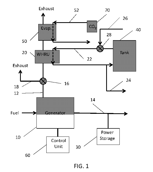
[0008] FIG. 1 is a schematic representation of a CHP system a carbon dioxide
evaporator, according to various embodiments of the present disclosure.
2
CA 02998374 2018-03-09
WO 2017/053242 PCT/US2016/052535
[0009] FIG. 2 is a schematic representation of a generator included in the CHP
system of FIG. 1, according to various embodiments of the present disclosure.
[0010] FIG. 3 is a schematic representation of a CHP system including a carbon
dioxide evaporator, according to various embodiments of the present
disclosure.
[0011] FIG. 4 is a schematic representation of a CHP system including an
electric
heater, according to various embodiments of the present disclosure.
[0012] FIGS. 5A and 5B are schematic representations of heat exchangers
according
to various embodiments of the present disclosure.
DETAILED DESCRIPTION OF THE EXEMPLARY EMBODIMENTS
[0013] The invention is described more fully hereinafter with reference to the
accompanying drawings, in which exemplary embodiments of the invention are
shown. This invention may, however, be embodied in many different forms and
should not be construed as limited to the exemplary embodiments set forth
herein.
Rather, these exemplary embodiments are provided so that this disclosure is
thorough,
and will fully convey the scope of the invention to those skilled in the art.
In the
drawings, the size and relative sizes of layers and regions may be exaggerated
for
clarity. Like reference numerals in the drawings denote like elements.
[0014] It will be understood that when an element or layer is referred to as
being
disposed "on" or "connected to" another element or layer, it can be directly
on or
directly connected to the other element or layer, or intervening elements or
layers may
be present. In contrast, when an element is referred to as being disposed
"directly on"
or "directly connected to" another element or layer, there are no intervening
elements
or layers present. It will be understood that for the purposes of this
disclosure, "at
least one of X, Y, and Z" can be construed as X only, Y only, Z only, or any
combination of two or more items X, Y, and Z (e.g., XYZ, XYY, YZ, ZZ). Herein,
when a first element is in "thermal communication" with a second element, heat
may
be transferred between the first and second elements.
3
CA 02998374 2018-03-09
WO 2017/053242 PCT/US2016/052535
[0015] FIG. 1 is a schematic diagram of a combined heat and power (CHP)
system,
according to various embodiments of the present disclosure. Referring to FIG.
1, the
CHP system includes a generator 10, a primary waste heat recovery unit (WHRU)
20,
a power storage 30, a tank 40, an evaporator 50, and a control unit 60.
[0016] Generally, in order to achieve high efficiency in a CHP system, both
electrical and thermal loads should be perfectly matched to generation. When
electrical demand is reduced, generator output is typically reduced (load
following),
which may also reduce thermal output. When thermal demand is reduced, exhaust
heat is typically diverted to maintain electrical output. Accordingly, both
scenarios
may reduce efficiency. Therefore, various embodiments provide a CHP system
that is
configured to maintain a high efficiency, during variations in electrical
and/or thermal
demands.
[0017] An exhaust conduit 12 extends from the generator 10 and through the
WHRU
20 and the evaporator 50. A power line 14 extends from the generator 10 to an
external load and the power storage 30. A circulation conduit 22 extends from
the
tank 40, through the WHRU 20 and back to the tank 40. An evaporation conduit
52
extends from a CO2 source 70, through the evaporator 50, and to an external
CO2
receptacle or conduit (not shown).
[0018] The generator 10 may be any suitable device configured to generate
electricity using a fuel, such as natural gas, biogas, or the like. The
generator 10 will
be discussed in more detail below with regard to FIG. 2. The exhaust conduit
12
provides hot exhaust output by the generator 10 to the WHRU 20 and the
evaporator
50.
[0019] The generator 10 may be connected to an external electric load (not
shown)
and the power storage 30 by the power line 14 (e.g., electrical bus or wire).
The
power storage 30 may include any suitable electrical storage device. For
example, the
power storage 30 may include one or more electrochemical storage devices, such
as a
battery, for example, a Li-ion battery, a NiCd battery, a NiMH battery, a lead-
acid
4
CA 02998374 2018-03-09
WO 2017/053242 PCT/US2016/052535
battery, or a flow battery. According to some embodiments, the power storage
30
may include one or more ultracapacitors or kinetic batteries.
[0020] The power storage 30 may be configured to store excess electrical power
generated by the generator 10. In other words, the power storage 30 may store
power
in excess of that required by an external load. Further, the power storage 30
may be
used to supplement the power generated by the generator 10, when an external
load
exceeds the power generation capacity of the generator 10.
[0021] The WHRU 20 may be configured as a heat exchanger having a shell and
tube gas to liquid (e.g., air-to-water) configuration. As such, the WHRU 20
may be
configured to heat a fluid, such as water, circulating in the circulation
conduit 22, by
extracting heat from the exhaust flowing through the exhaust conduit 12. The
heated
fluid may be stored in the tank 40 for later use, or may be provided to an
external
process using an output conduit 24. For example, the heated fluid may be used
to
reduce a demand for boiler heating. The tank 40 may be an insulated hot water
storage tank, a boiler, a contaminated water storage tank, or any suitable hot
fluid
storage vessel.
[0022] Further, additional fluid may be added to the system via an input
conduit 26
connected to the circulation conduit 22. In particular, the input conduit 26
may be
connected to a pump or valve 28 configured to pump fluid from the tank 40
and/or the
input conduit 26 through the circulation conduit. The fluid may be, for
example, non-
potable water, potable water, glycol, or a water/glycol solution, and or any
other
suitable heat retaining fluid. In some embodiments, the pump or valve 28 may
be a
valve configured to control a flow of the fluid there through. In other
embodiments,
the pump or valve 28 may be a pump or a pump/valve combination.
[0023] The WHRU 20 may also be configured to pasteurize the fluid. In
particular,
the WHRU 20 may include a first chamber through which the exhaust flows, and a
second chamber through which the fluid flows. The chambers are configured to
allow
heat exchange between the exhaust and the fluid. The exhaust may have a
temperature that is greater than a water pasteurization temperature (e.g., a
temperature
CA 02998374 2018-03-09
WO 2017/053242 PCT/US2016/052535
of greater than 500 C, such as a temperature ranging from about 250 to about
1000 C). As the fluid flows through the second chamber, the fluid may be
heated to a
pasteurization temperature due to heat exchange. The flow rate of the fluid
through
the chamber may be controlled to heat the fluid for a time period and at
temperature
sufficient to adequately pasteurize/disinfect the fluid. As such, if non-
potable water is
used as the fluid (e.g., the fluid supplied through the input conduit 26), the
non-
potable water may be rendered safe for use in gray water applications. For
example,
the pasteurized/disinfected water may be supplied from the output conduit 24
and used
for, for example, irrigation or the like.
[0024] The control unit 60 may include a central processing unit and a memory.
For
example, the control unit 60 may be a server, a application specific control
circuit
(e.g., an ASIC chip) or a general purpose computer, loaded with appropriate
control
software. The control unit 60 may be integrated with the CHP system, or may be
electrically connected to the CHP system from a remote location.
[0025] The control unit 60 may be configured to control the operation of the
CHP
system. In particular, the control unit 60 may detect a load applied to the
generator
10, and may control whether the power storage 30 is charged or discharged
accordingly. For example, the control unit 60 may charge the power storage 30,
when
the power output of the generator 10 exceeds a load power demand applied
thereto,
and may discharge the power storage when a load power demand exceeds the power
output of the generator 10.
[0026] The CHP system may include temperature and/or fluid level sensors in
the
tank 40 and/or the output conduit 24. Further, the control unit 60 may detect
a
demand for the fluid in the tank 40. The control unit 60 may also detect when
the
fluid level in the tank 40 is below a threshold level and/or when the
temperature of a
fluid in the tank 40 is below a threshold temperature using fluid level and/or
temperature sensors in the tank. When a demand for heated fluid is low or
absent
(e.g., a demand for fluid output from the output conduit 26), the control unit
60 may
be configured to provide heated fluid to the tank 40, by operating the pump or
valve
6
CA 02998374 2018-03-09
WO 2017/053242 PCT/US2016/052535
28 to move the fluid in the circulation conduit 22 between the tank 40 and the
WHRU,
or heat the fluid in the tank 40 using a tank heater. When the tank 40 is
filled with
fluid heated to a desired temperature (e.g., the maximum operating temperature
of the
tank 40), the control unit 60 may open a valve 16 to divert the exhaust into a
diversion
conduit 18. The control unit 60 may be configured to sent control signals to
the pump
or valve 28, the valve 16, the generator 10, and/or the power storage 30.
[0027] The evaporator 50 is disposed on the exhaust conduit 12 downstream from
the WHRU 20, with respect to a direction the exhaust flows through the exhaust
conduit from the generator 10. Since the WHRU 20 extracts heat from the
exhaust,
the exhaust in received by the evaporator 50 may have a lower temperature than
when
the exhaust is received by the WHRU 20.
[0028] Conventionally, such relatively low-temperature exhaust was not
considered
to be useful and was simply vented. However, the present inventors discovered
that
such low-temperature exhaust may be utilized for certain processes that
require
relatively low amounts of thermal energy. In particular, such low-temperature
exhaust
may be utilized for the evaporation of compressed liquid CO2, which is used by
many
breweries and food processors.
[0029] Accordingly, after passing through the WHRU 20, the low-temperature
exhaust in the exhaust conduit 12 is provided to the evaporator 50. Liquid CO2
may
be provided from a CO2 source 70 (e.g., a compressed CO2 storage vessel) to
the
evaporator 50, via an evaporation conduit 52. The evaporator 50 may be
configured
as a shell and tube gas-to-liquid heat exchanger. As such, the evaporator 50
may be
configured to convert the liquid CO2 into a gas (e.g., CO2 gas), which may
then be
provided for external use (e.g., for brewing or food processing). According to
some
embodiments, the evaporator 50 may be omitted.
[0030] FIG. 2 is a schematic of components of the generator 10, according to
various
embodiments of the present disclosure. Referring to FIG. 2, the generator 10
may
include an ignition chamber 100, a turbine 110, and an electrical generator
120. The
7
CA 02998374 2018-03-09
WO 2017/053242 PCT/US2016/052535
generator 10 may also include a blower or compressor 130, a compressor 140,
and a
burner 150.
[0031] A fuel conduit 162 may connect the compressor 140 and the burner 150 to
a
fuel supply 160. The fuel supply 160 may be a conduit, such as a natural gas
pipeline,
or may be a fuel storage tank containing a hydrocarbon fuel. The hydrocarbon
fuel
may be, for example, natural gas, methane, propane, or butane. However, other
fuels
may also be utilized. The compressor 140 operates to compress the fuel and
then
supply the compressed fuel to the ignition chamber 100. In particular, fuel at
a
relatively low pressure (e.g., 80-120 psig) may flow from the fuel supply 160
to the
compressor 140. The compressor 140 may then further pressurize the fuel to a
relatively high pressure (e.g., 300-340 psig) and supply the highly
pressurized fuel to
the ignition chamber 100. At the same time, the blower or compressor 130 may
operate to feed room temperature air into the ignition chamber 100.
[0032] The ignition chamber 100 may include an igniter (not shown), such as an
electric spark generator, a flame generator, or other like apparatus. In the
ignition
chamber 100, the pressurized fuel mixes with the air and is ignited, producing
a
gaseous exhaust having a high temperature and a pressure.
[0033] The exhaust is fed at high speed from the ignition chamber 100 to the
turbine
110 through a turbine inlet conduit 102. The high-speed flow of exhaust causes
blades of the turbine 110 to rotate, producing rotation in an output shaft 112
connecting the turbine 110 to the electrical generator 120. The electrical
generator
120 converts this rotation into electricity. According to some embodiments, a
reciprocating engine may be used in place of the turbine 110.
[0034] Exhaust from the turbine 110 is fed to the exhaust conduit 12. The
burner
150 may be disposed in fluid communication with the exhaust conduit 12
downstream
from the turbine 110 and upstream from the WHRU 20, with respect to a flow
direction of the exhaust. The burner 150 may receive fuel from the fuel supply
160
and may include an igniter similar to the ignition chamber 100. An optional
second
blower or compressor 131 may provide air to the burner 150, which allows the
burner
8
CA 02998374 2018-03-09
WO 2017/053242 PCT/US2016/052535
150 to operate as independent heat source and provide hot exhaust gas into the
exhaust
conduit 12, where it may mix with exhaust from the turbine 110. The burner 150
may
ignite the fuel to supply additional heat to the exhaust stream. In some
embodiments,
the burner 150 may receive compressed fuel from the compressor 140. However,
in
other embodiments, the burner 150 may be omitted.
[0035] FIG. 3 illustrates a CHP system according to various embodiments of the
present disclosure. The CHP system of FIG. 3 is similar to the CHP system of
FIG. 1,
so only the differences therebetween will be described in detail.
[0036] Referring to FIG. 3, the CHP system includes an evaporator 54 disposed
on
or in fluid communication with the circulation conduit 22 and connected to a
carbon
dioxide source 70 by an evaporation conduit 52. The evaporator 54 may be
disposed
downstream of the WHRU 20, with respect to a flow direction of fluid in the
circulation conduit 22. The evaporator 54 may be configured as a heat
exchanger
having a plate and frame or a brazed plate liquid-to-liquid heat exchange
configuration. The evaporator 54 may have a direct heat exchange configuration
or an
indirect heat exchange configuration that includes water or glycol as a heat
exchange
media.
[0037] FIG. 4 illustrates a CHP system according to various embodiments of the
present disclosure. The CHP system of FIG. 4 is similar to the CHP system of
FIG. 1,
so only the differences therebetween will be described in detail.
[0038] Referring to FIG. 4, the CHP system includes one or more electric
heaters 80,
81 (e.g., electrical resistance heaters) disposed in thermal communication
with the
circulation conduit 22 and/or the tank 40, and electrically connected to the
generator
and/or the power storage 30 via the power line 14. The heaters 80, 81 may be
configured to heat fluid in the circulation conduit 22 when a load applied to
the
generator 10 is less than the electrical power output of the generator 10. The
heaters
80, 81 may operate to convert excess electrical power provided by the
generator 10
into heat, which may used to heat the fluid in the circulation conduit 22
and/or stored
in the tank 40. In other embodiments, the heater 81 may be integrated with the
tank
9
CA 02998374 2018-03-09
WO 2017/053242 PCT/US2016/052535
40, to directly heat the fluid in the tank 40. In various embodiments, the CHP
system
may include both heaters 80, 81 or one of the heaters 80, 81 may be omitted.
[0039] The heater 80 may be disposed on the circulation conduit 22 upstream of
the
evaporator 54, or may be incorporated into the evaporator 54. Accordingly, the
heater
80 may be used to pre-heat the fluid in the circulation conduit 22, such that
carbon
dioxide evaporation may begin before the generator 10 reaches an operating
temperature. In addition, the heater 80 may be configured to directly or
indirectly heat
the evaporator 54 using electrical power from the power storage 30, such that
carbon
dioxide evaporation may occur when the generator is not operating. In still
other
embodiments, the heater 80 may be configured to directly or indirectly heat
the
evaporator 50 of FIG. 1, such that the evaporator 50 may be operated using the
power
storage 30 when the generator 10 is not operating.
[0040] FIGS. 5A and 5B respectively illustrate heat exchangers 200, 220,
according
to various embodiments of the present disclosure. The heat exchangers 200, 220
may
exemplify any of the WHRU's and/or evaporators described above.
[0041] Referring to FIG. 5A, the heat exchanger 200 may include a first
chamber
202, a second chamber 204, which are separated by a partition 206. A first
fluid may
flow into the first chamber 202 through an input conduit 208, and out of the
first
chamber 202 through an output conduit 210. A second fluid may flow into the
second
chamber 204 through an input conduit 212, and out of the second chamber 204
through an output conduit 214. In some embodiments, the first and second
fluids may
be different ones of exhaust, carbon dioxide, and a working fluid such as
water.
[0042] As such, the heat exchanger 200 may be a counter-current heat exchanger
having a counter current fluid flow. However, in other embodiments, the input
and
output conduits of one of the chambers 202, 204 may be reversed, such that the
heat
exchanger 200 may be a co-flow heat exchanger having a co-current flow. In
some
embodiments, the heat exchanger may be a cross-flow heat exchanger having a
cross-
current fluid flow. Heat may be exchanged between the first and second fluids
through
the partition 206.
CA 02998374 2018-03-09
WO 2017/053242 PCT/US2016/052535
[0043] Referring to FIG. 5B, the heat exchanger 220 includes an outer chamber
222
and an inner chamber 224, which are separated by a partition 223. The outer
chamber
222 may surround the inner chamber 224. For example, the inner chamber 224 may
be columnar, and the outer channel 222 may be annular.
[0044] A first fluid may flow into the outer chamber 222 through an input
conduit
225 and may exit the first chamber through an output conduit 226. A second
fluid
may flow into the inner chamber 224 through an input conduit 228 and may exit
the
first chamber through an output conduit 230. In some embodiments, the first
and
second fluids may be different ones of exhaust, carbon dioxide, and a working
fluid
such as water.
[0045] According to some embodiments, a CHP system may include any
combination of the elements shown in FIGS. 1-5B. For example, the present
disclosure encompasses a CHP system that may include the evaporator of FIG. 2,
the
evaporator of FIG. 3, and/or the heater(s) 80, 81 of FIG. 4. A CHP system may
also
include any of the heat exchangers 200, 220 shown in FIGS. 5A and 5B.
[0046] According to various embodiments, the present disclosure provides a
method
of operating a CHP system according to different output requirements. The
method
may include: operating the CHP system in a first mode, when substantially all
of the
electrical and thermal output of the CHP system is needed; operating the CHP
system
in a second mode when less than the maximum electrical output of the generator
is
needed, while substantially all of the thermal output of the CHP system is
needed; and
operating the CHP system in a third mode, when the electrical demand exceeds
the
electrical output of the generator and the thermal demand is relatively low.
[0047] In the first mode, the control unit may operate the generator at full
power
output and may capture heat from the exhaust by circulating fluid in the
circulation
conduit. The heated fluid may be provided to directly external processes. In
the
alternative, the heated fluid may be stored in the tank and/or provided from
the tank to
the external process. The power output of the generator may be provided to an
external load.
11
CA 02998374 2018-03-09
WO 2017/053242 PCT/US2016/052535
[0048] In the second mode, the control unit may operate the generator at full
power
output. The generated power may be provided to an external load, and any
excess
power may be stored in the power storage. The fluid may also be heated and
stored in
the tank, provided to an external process, or a combination thereof. Once the
power
storage is fully charged/full, the output of the generator may be reduced to
match
external thermal requirements. In the alternative, the generator may be turned
off, and
the burner may be used to heat the fluid and satisfy the thermal requirements.
[0049] In the third mode, the control unit may operate the generator at full
power
output and electrical requirements in excess of the capacity of the generator
may be
compensated for by discharging power from the power storage. The fluid may
also be
heated and stored in the tank, provided to an external process, or a
combination
thereof. If the fluid in the tank reaches/approaches the maximum operating
temperature of the tank, the exhaust from the generator may be vented through
the
vent conduit. In the alternative, fluid flow through the circulation conduit
may be
stopped.
[0050] According to some embodiments, the method may include operating the CHP
system in a forth mode, when substantially all or less than all of the
electrical output
of the CHP system is needed, and thermal requirements cannot be met my
transferring
heat from only the turbine exhaust. The fourth mode may include operating the
generator full power output, while operating the burner.
[0051] The generated power may be provided to an external load, and any excess
power may be stored in the power storage. Since the generator exhaust includes
heat
from the turbine exhaust and optionally from the burner, the WHRU may recover
additional heat, as compared to when the burner is not operated. Accordingly,
the
fluid may be heated to a higher temperature, or the circulation rate of the
fluid may be
increased. Thus, the thermal output of the CHP system may be increased.
[0052] As noted above, the above method allows for the generator to be
operated at
full power, even when electrical and/or thermal demands are relatively low, by
capturing excess electrical and thermal energy in the power storage and the
tank,
12
CA 02998374 2018-03-09
WO 2017/053242 PCT/US2016/052535
respectively. As such, the efficiency of the CHP system may be unexpectedly
increased.
[0053] The foregoing description of the invention has been presented for
purposes of
illustration and description. It is not intended to be exhaustive or to limit
the invention
to the precise form disclosed, and modifications and variations are possible
in light of
the above teachings or may be acquired from practice of the invention. The
description was chosen in order to explain the principles of the invention and
its
practical application. It is intended that the scope of the invention be
defined by the
claims appended hereto, and their equivalents.
13