Note: Descriptions are shown in the official language in which they were submitted.
CA 02998821 2018--14
WO 2017/059840
PCT/0E2016/100397
Grid sensor system for characterizing a fluid flow
The invention relates to a grid sensor system for
incorporation into an installation through which a
fluid flow flows, for characterizing the fluid flow.
The grid sensor system is suitable for example for
industrial applications for use at high temperatures
and pressures, and may be used for example for
investigating gas and liquid flows, in particular
multiphase fluid flows.
Grid sensors are sensors with electrodes which are
arranged in a grid-like manner and which serve for
spatially resolved and temporally resolved measurement
of the properties of fluid flows over the flow cross
section thereof (for example in the cross section of
pipelines or containers). Grid sensors are usually used
to determine the local, instantaneous gas content in
two-phase flows, but they are suitable for example also
for measurement of mixing processes in single-phase
media during the addition of tracers, such as for
example salt solutions.
Grid sensors have electrodes which are arranged in a
grid-like manner such that crossing points are formed,
wherein for example, it is possible for a plurality of
electrodes which run in a first grid plane and a
plurality of counter electrodes which run in a second
grid plane to be provided, which electrodes are
arranged in a grid-like manner such that crossing
points are formed. The electrode grid or measuring grid
formed in such a manner is introduced into the fluid
flow which is to be characterized. The measurement
principle is based on the fact that, at the crossing
points of the electrode grid, the electrical
conductivity (or some other electrical property)
prevailing between the electrodes of the respective
crossing point is detected, and is used as a measure
CA 02998821 2018-03-14
WO 2017/059840
PCT/DE2016/100397
- 2 -
for the physical or chemical properties of the fluid
flow prevailing at the crossing point at the point in
time of the measurement. Grid sensors may be designed
for example for detecting the spatial distribution of
the electrical conductivity of the flow medium over the
flow cross section, in that the electrodes of the first
grid plane have predefined voltage signals applied to
them one after the other, and the resulting current
signal is detected and evaluated at the counter
electrodes of the second grid plane.
The measurement principle may therefore be based for
example on the spatially and temporally highly resolved
measurement of the electrical conductivity or
permittivity of the flow medium in a measuring grid
which consists of two planes (transmitting plane and
receiving plane) of parallel electrodes which, relative
to one another, are arranged with a small axial offset
and at an angle of, normally, 90 . At the virtual
crossing points which are thus formed, it is possible
for the cross section to be completely scanned by way
of multiplexing of the transmitting electrodes and
simultaneously fully parallel measurement at the
receiving electrodes. For example, in the case of the
presence of a multiphase fluid flow with an
electrically conductive phase and an electrically non-
conductive phase, it is thus possible for these two
phases to be differentiated by means of detection of
the electrical conductivity, and for example by means
of the grid sensor for the fractions of these two
phases at the fluid flow to be determined.
Grid sensors for characterizing fluid flows are
described for example in DE 196 49 011 Al, DE 10 2005
019 739 B3, DE 10 2006 019 178 Al and DE 10 2007 019
926 Al. US 5 287 752 A describes a sensor with two
plates, wherein the first plate has a plurality of
electrode segments which are arranged in the form of a
CA 02998821 2018-03-14
WO 2017/059840
PCT/DE2016/100397
- 3 -
matrix, and the second plate has at least one
continuous electrode, such that an electrode segment of
the first plate forms in each case a capacitive sensor
with the electrode of the second plate.
Conventionally, in order to insert a grid sensor into a
flow-guiding installation (as an example into a flow-
guiding pipeline), the grid sensor is clamped between a
supplying pipe segment and a discharging pipe segment
of the flow-guiding pipeline, for example between a
flange of the supplying pipe segment and a flange of
the discharging pipe segment. In order to ensure the
leak-tightness, the grid sensor is subjected to a high
clamping pressure, which, for example due to the
associated material loading, can be a disadvantage. In
order to remove the grid sensor from the installation
(for example for replacement purposes, maintenance
purposes, cleaning purposes, repair purposes, etc.), it
is necessary for the corresponding part of the flow-
guiding installation to be disassembled, wherein, after
releasing the flange connections, the supplying pipe
segment and the discharging pipe segment have to be
forced apart in order to release the clamping pressure
acting on the grid sensor arranged therebetween, and
the grid sensor is subsequently removed from the
installation. Consequently, the removal of the grid
sensor (or the measuring grid) from the installation to
be characterized is associated with high work and time
expenditure.
Provided by way of the invention is a grid sensor
system for incorporating a grid sensor element into a
fluid flow, by means of which system an uncomplicated
incorporation of a grid sensor or sensor grid into the
flow-guiding installation to be characterized and an
uncomplicated removal of the grid sensor from the flow-
guiding installation is made possible, and by moans of
which system a low material loading of the grid sensor
- 4 -
element is made possible. The fluid flow may be a single-
phase or multiphase fluid flow.
Provided according to the invention is a grid sensor
system which serves for incorporation into a fluid-flow-
guiding installation for the purpose of characterizing
the fluid flow. The grid sensor system is also referred
to as "grid sensor device". The grid sensor system has a
flow guide with an insert holder and a sensor insert.
Certain exemplary embodiments can provide a grid sensor
system for incorporation into an installation which
guides a fluid flow, for characterizing the fluid flow,
comprising: a sensor insert, and a flow guide with an
inlet line for the admission of the fluid flow, with an
outlet line for the discharge of the fluid flow, and with
an insert holder, arranged between the inlet line and the
outlet line, for holding the sensor insert, wherein the
flow guide is designed such that it forms a rectilinear
flow path which runs from the inlet line through the
insert holder to the outlet line, the insert holder has
an insert opening and is designed such that it defines a
predefined insertion direction which runs transversely
to the flow path, and such that the sensor insert is able
to be inserted through the insert opening into the insert
holder along the predefined insertion direction, the
sensor insert has a grid sensor element with a plurality
of electrodes arranged in a grid like manner forming
crossing points, and has connecting lines for the
electrical contacting of the electrodes, and the sensor
insert is designed such that, when the sensor insert is
held in the insert holder, none of the electrodes runs
parallel to the insertion direction.
CA 2998821 2019-03-20
- 4a -
The sensor insert has a (that is to say at least one)
grid sensor element comprising a measuring grid or
electrode grid with a plurality of electrodes arranged
in a grid-like manner. The sensor insert also has
electrically conductive connecting lines for the
electrical contacting of the electrodes of the measuring
grid. The connecting lines may for example be in the form
of connecting wires. It may also be provided that the
connecting lines are formed integrally with the
electrodes, wherein for example, a first section of a
wire functions as an electrode and a second section of
the wire functions as a connecting line. The electrodes
of the electrode grid may be formed for example as
electrically conductive wires, rods or tubes.
The electrode grid may have for example a plurality of
electrodes which function as transmitting electrodes and
a plurality of electrodes which function as receiving
electrodes, wherein the transmitting electrodes are
arranged so as to run in a first plane, and the receiving
electrodes are arranged so as to run in a second plane,
wherein the first and the second plane are parallel to
one another and are arranged at a distance from
one another. The transmiLting electrodes and the
receiving electrodes are arranged in a grid-like
manner such that their projections cross (referred
CA 2998821 2019-03-20
CA 02998821 2018-03-14
WO 2017/059840
PCT/DE2016/100397
- 5
to hereinafter as "crossing points"), wherein, at each
grid crossing point, one of the transmitting electrodes
and one of the receiving electrodes of the electrode
grid cross. Preferably, both the transmitting
electrodes and the receiving electrodes are formed to
run rectilinearly or are of rod-like form, wherein all
transmitting electrodes run parallel to one another
along a first longitudinal direction in the first
plane, and all receiving electrodes run parallel to one
another along a second longitudinal direction in the
second plane, and wherein the first longitudinal
direction is not parallel to the second longitudinal
direction. The first and the second longitudinal
direction preferably form an angle of 90 . The first
and the second plane are also referred to as "first
grid plane" and "second grid plane", respectively.
The grid sensor element may have for example a sensor
frame, wherein the electrodes of the electrode grid are
fastened on the sensor frame such that they are
electrically insulated with respect to one another and
with respect to the ground potential. The sensor frame
has a through opening for the passage of the fluid
flow, wherein the grid electrodes are fastened on the
sensor frame so as to run over said through opening.
The sensor frame preferably consists of an electrically
insulating material, for example of a ceramic.
Accordingly, the sensor frame may consist for example
of one or more ceramic plates. It may also be provided
that the sensor frame is formed from a circuit card or
a circuit board, and the grid sensor element is formed
for example as a so-called circuit card sensor.
The connecting lines serve for the electrical
contacting of the electrodes of the electrode grid, for
example for applying a voltage signal to the
transmitting electrodes and for picking off a resulting
response signal from the receiving electrodes. Each of
CA 02998821 2018-03-14
WO 2017/059840
PCT/DE2016/100397
- 6 -
the electrodes of the electrode grid is contacted by a
separate connecting line.
The flow guide has an inlet line for the admission of
the fluid flow. The inlet line functions as an inlet
zone and serves for connecting the flow guide to a
flow-supplying part (for example a supplying pipe
segment) of the flow-guiding installation to be
characterized, it being possible for the inlet line to
be provided for example with a flange for this purpose.
The flow guide also has an outlet line for the
discharge of the fluid flow. The outlet line functions
as an outlet zone and serves for connecting the flow
guide to a flow-discharging part (for example a
discharging Pipe segment) of the flow-guiding
installation, it being possible for the outlet line to
be provided for example with a flange for this purpose.
The flanges may for example be in the form of standard
flanges. The insert holder is arranged between the
inlet line and the outlet line and is designed for (at
least partially) holding the sensor insert. Both the
inlet line and the outlet line open into the insert
holder. The flow guide is designed such that it forms a
rectilinear flow path which runs from the inlet line
through the insert holder to the outlet line. That is
to say, the inlet line, the insert holder and the
outlet line define a rectilinear flow path with a flow
direction running from the inlet line to the outlet
line. The flow guide serves for the incorporation or
connection of the actual grid sensor at the flow-
guiding installation to be characterized and is
therefore also referred to as "connecting device" or as
"main body".
The insert holder is a holder device for holding the
sensor insert and has a holder cavity for (at least
partially) holding the sensor insert. The insert holder
has an insert opening and is designed such that the
CA 02998821 2018--14
WO 2017/059840
PCT/DE2016/100397
- 7 -
sensor insert is able to be inserted or introduced into
the insert holder along an insertion direction, wherein
the insertion direction runs transversely to the flow
path formed by the flow guide (and thus transversely to
the flow direction defined by said flow path). The
insert holder may therefore be designed such that it
defines a predefined insertion direction along which
the sensor insert is able to be inserted into the
insert holder and thus (at least partially) into the
holder cavity. The insert holder is thus able to allow
guided movement and insertion of the sensor insert
along the insertion direction predefined by means of
the insert holder. The insert holder may in particular
have an insertion guide which is formed for the guided
movement of the sensor insert along an insertion
direction, predefined by means of the insertion guide,
such that the sensor insert is able to be inserted into
the insert holder in a guided manner along the
predefined insertion direction. The insertion guide may
for example be designed in the form of a mechanical
guide element or be formed by the geometry of the
insert holder and of the holder cavity. The insertion
guide may be designed in particular as a straight guide
(for example as a linear guide), by means of which
guided, one-dimensional movement and insertion of the
sensor insert into the insert holder along a straight
line is made possible. The insert holder may therefore
be formed in particular such that it prevents movement
of the sensor insert transverse or perpendicular to the
insertion direction (with the result that the sensor
insert is guided laterally by means of the insert
holder). It is thus possible for the insert holder to
be formed in particular such that it allows guided,
one-dimensional (rectilinear) movement and insertion of
the sensor insert along the insertion direction, and
prevents movement of the sensor insert transverse or
perpendicular to the insertion direction, such that the
sensor insert is able to be inserted into the insert
CA 02998821 2018--14
WO 2017/059840
PCT/DE2016/100397
- 8 -
holder in a guided manner rectilinearly along the
insertion direction. The insert holder may be designed
for example in the form of a cuboidal housing which is
connected between the inlet line and the outlet line
and in which the insert opening and the holder cavity
are formed.
Consequently, the flow path defined by the flow guide
is surrounded toward the sides by the side wall of the
flow guide, and the insert opening is formed in the
side wall of the flow guide (in particular in the side
wall of the insert holder section of the flow guide)
such that the sensor insert is able to be inserted
laterally into the flow guide, which functions as a
connecting device. The insertion direction may
accordingly run for example perpendicularly or at right
angles to the flow path defined by the flow guide (and
thus perpendicularly to the flow direction defined by
this flow path), with the result that the insertion
direction may in particular be at right angles to the
axial direction of the inlet line and of the outlet
line. The sensor insert may be inserted laterally into
the flow guide or the main body and may be sealed off
in a fluid-tight manner, for example so as to be
pressure- and vapor-resistant, by means of a seal (for
example graphite, copper or board, depending on usage
condition).
The sensor insert may be designed such that, when the
sensor insert is held in the insert holder, the grid
planes of the electrode grid are perpendicular to the
flow path or the flow direction defined thereby.
The fact that the grid sensor element is provided as a
constituent part of the sensor insert means that it is
not necessary to apply large forces to the grid sensor
element for the purpose of ensuring the leak-tightness,
and so the grid sensor element does not have to be
CA 02998821 2018--14
WO 2017/059840
PCT/DE2016/100397
- 9 -
subjected to any high material loads. The fact that the
grid sensor element is present as a constituent part of
the sensor insert means that an uncomplicated removal
of the grid sensor element from the flow-guiding
installation to be characterized and an uncomplicated
introduction of the grid sensor element into the
installation is made possible, wherein in particular
the flow guide, functioning as a connecting device, of
the grid sensor system may remain in the installation.
Moreover, the sensor insert and thus also the fastening
of the grid sensor, the sealing against the escape of
fluid and the line routing of the connecting lines may
be retained independently of the connection design (for
example of the connection geometry), which is
predefined by the flow-guiding installation to be
characterized. As a result of this structure and the
uncomplicated handling, the grid sensor system is
highly suitable for industrial applications, for
example for characterizing installations in which fluid
flows are present at high temperatures and pressures.
The insert holder and the sensor insert may be designed
such that, when the sensor insert is held in the insert
holder as intended, the insert opening is closed off by
means of, or by, the sensor insert. It may be provided
for example that the sensor insert has a closure
section for closing off the introduction opening such
that, when the sensor insert is held in the insert
holder (as intended), the introduction opening is
closed off by the closure section. In order to ensure
the fluid-tightness, it is possible for seals and
closure means (for example screws or clamping means) to
be provided.
According to one embodiment, the sensor insert has an
insert element, wherein the insert element has a holder
section for holding the grid sensor element and a
closure section for closing off the insert opening.
CA 02998821 2018-03-14
WO 2017/059840
PCT/DE2016/100397
- 10 -
When the grid sensor system is used as intended, the
grid sensor element is held on or in the holder
section. The closure section is designed such that,
when the sensor insert is held in the insert holder (as
intended), the insert opening is closed off by the
closure section.
The insert element may be of integral form, wherein the
holder section and the closure section are formed
integrally with one another as a single-piece
component. It may also be provided, however, that the
insert element is of multi-part form.
According to one embodiment, the sensor insert has (for
example as a constituent part of the insert element) a
positioning device for the variable setting of the
relative positioning between the holder section and the
closure section. Accordingly, it may be provided for
example that the holder section and the closure section
of the insert element are present as separate
components and are coupled to one another so as to be
movable relative to one another by means of the
positioning device.
The fact that the positioning of the holder section
relative to the closure section is adjustable means
that the positioning of the grid sensor element, held
on the holder section, in relation to the flow path can
be adjusted and thus set according to requirements (for
example such that, when the sensor insert is held in
the insert holder, the electrode grid is arranged
centrally in relation to the flow cross section).
According to one embodiment, the positioning device is
designed for the variable setting of the spacing
between the holder section and the closure section, and
so the spacing between the holder section and the
closure section of the insert element is able to be
CA 02998821 2018-03-14
WO 2017/059840
PCT/DE2016/100397
- 11 -
adjusted by means of the positioning device. The
positioning device may be designed for example such
that, by means of the positioning device, the spacing,
present along the insertion direction (when the sensor
insert is held in the insert holder), between the
holder section and the closure section is settable in a
variable manner. Consequently, positioning of the grid
sensor element is made possible in a simple way.
According to one embodiment, the insert element has a
holder recess with a recess bottom, and has a fixing
cover, at the holder section, wherein the grid sensor
element is held in the holder recess between the recess
bottom and the fixing cover. Accordingly, the grid
sensor element can be protected on both sides by the
insert element and the fixing cover. By means of the
fixing cover provided releasably on the rest of the
insert element, it is possible for the grid sensor
element to be taken out of the holder recess by means
of release and removal of the fixing cover and to be
fixed in the holder recess by means of fastening of the
fixing cover on the rest of the insert element.
Through openings for the passage of the fluid flow are
provided on the recess bottom and in the fixing cover.
It may be provided in particular that the through
openings provided in the recess bottom and on the
fixing cover have the same geometry as the through
opening defined by the sensor frame of the grid sensor
element (wherein for example all of these through
openings may be formed to be circular with the same
diameter).
It may also be provided that the inlet mouth opening,
by way of which the inlet line opens into the insert
holder, and/or the outlet mouth opening, by way of
which the outlet line opens into the insert holder,
have the same geometry as the through opening defined
CA 02998821 2018-03-14
WO 2017/059840
PCT/DE2016/100397
- 12 -
by the sensor frame of the grid sensor element (wherein
for example all of these through openings may be formed
to be circular with the same diameter).
It may be provided that the sensor insert has a
leadthrough device with one or more (fluid-tight)
leadthroughs for leading the connecting lines out of
the insert holder, wherein the leadthroughs are
arranged such that and the connecting lines are led
through the leadthroughs such that, when the sensor
insert is held in the insert holder, the connecting
lines are led from a region inside the insert holder or
holder cavity into a region outside the insert holder
or holder cavity by means of the leadthrough device.
The leadthroughs may be formed for example at the
closure section of the insert element such that it is
possible for the connecting lines to be led out of the
interior of the insert holder through the closure
section to the outside by means of the leadthroughs.
The leading-through of the connecting lines may be
realized for example via glands which are suitable for
high temperatures and pressures (for example graphite
stuffing boxes). In order to save space, multiple
leadthroughs may be used. In accordance with the usage
case, for example graphite, Viton, NBR, PEEK or PTFE
may be taken into consideration as a sealing material
for the fluid-tight sealing of the leadthroughs,
wherein graphite is suitable, in particular, for wet
vapor applications.
According to one embodiment, at least one of the
leadthroughs is formed as a multiple leadthrough,
wherein a plurality of the connecting lines provided
for the electrical contacting of the electrodes are led
through said leadthrough. The fact that one or more
such multiple leadthroughs are provided means that the
number of leadthroughs which are to be kept fluid-tight
CA 02998821 2018-03-14
WO 2017/059840
PCT/DE2016/100397
- 13 -
can be kept small. It may be provided that a plurality
of connecting lines are led through each of the
leadthroughs. It may be provided in particular that
just a single leadthrough is provided and all the
connecting lines are led through said leadthrough.
According to one embodiment, the grid sensor element
has a sensor frame, wherein the electrodes of the
electrode grid are fastened in the sensor frame, the
electrodes are contacted by the connecting lines, and
the connecting lines are arranged so as to run without
any tensile stress in a region between the sensor frame
and the leadthrough device. It may be provided in
particular that the connecting lines are arranged so as
to run without any tensile stress and in a loose manner
in the region between the sensor frame and the
leadthrough device. Accordingly, it may be provided
that the connecting lines are arranged so as to run
without any tensile stress between the sensor frame and
the leadthrough device, or between the electrodes and
the leadthrough device.
It may be provided for example that the grid sensor
element has a sensor frame, wherein the electrodes of
the electrode grid are fastened in the sensor frame,
wherein each of the electrodes is contacted in an
electrically conductive manner at the sensor frame
(that is to say in the region of the sensor frame) by
one of the connecting lines, and wherein each of the
connecting lines is led through one of the leadthroughs
and is thus led out of the insert holder. Accordingly,
the connecting lines are formed and arranged such that,
in a region between the sensor frame and the
leadthroughs (through which they are in each case led),
they are not under tensile stress but run in a loose
manner. The electrodes of the electrode grid may be
clamped for example in the sensor frame, that is to say
fastened in the sensor frame so as to be under tensile
CA 02998821 2018-03-14
WO 2017/059840
PCT/DE2016/100397
- 14 -
stress. In other words, it is thus accordingly the case
that, each of the electrodes is contacted at one
contacting point by one of the connecting lines, and
each of the connecting lines is led through one of the
leadthroughs, wherein the connecting lines are arranged
so as to run without any tensile stress in a region
between the respective contacting point and the
assigned leadthrough.
The fact that the connecting lines are arranged without
any tensile stress in the region arranged ahead of the
leadthroughs means that simple positioning of the
connecting lines is made possible, with the result
that, for example, the connecting lines can be led out
of the insert holder at any desired positions, and so,
for example, the positioning of the leadthroughs does
not have to be formed so as to correspond to the
positioning of the electrodes of the electrode grid,
and so it is also possible for the leadthroughs to be
positioned in any desired way. This significantly
facilitates in particular the formation of the
leadthroughs as multiple leadthroughs.
The sensor insert may be designed such that, when the
sensor insert is held in the insert holder (as
intended), none of the electrodes of the electrode grid
runs parallel to the insertion direction.
The spacing to be bridged by the connecting lines
extends along the insertion direction. The fact that
the electrodes are arranged so as to run with their
longitudinal direction not parallel to the insertion
direction means that an arrangement of the connecting
lines without any tensile stress can be promoted.
lt may be provided in particular that the electrode
grid has a plurality of electrodes which function as
transmitting electrodes and a plurality of electrodes
CA 02998821 2018-03-14
WO 2017/059840
PCT/DE2016/100397
- 15 -
which function as receiving electrodes, wherein all the
transmitting electrodes are arranged so as to run
parallel to one another along a first longitudinal
direction in a first grid plane, and all the receiving
electrodes are arranged so as to run parallel to one
another along a second longitudinal direction in a
second grid plane, wherein the first and the second
plane are parallel to one another, and the first and
the second longitudinal direction form an angle of 900
with one another. According to this configuration, the
sensor insert may be designed for example such that,
when the sensor insert is held in the insert holder,
the two grid planes are arranged perpendicularly to the
flow path or the flow direction, and both the first and
the second longitudinal direction form an angle of 45
with the insertion direction. This symmetric
configuration allows a particularly uncomplicated and
space-optimized arrangement of the connecting lines.
It may be provided that the inlet line and the outlet
line have the same inner cross section over their
entire length.
According to one embodiment, the inlet line and/or the
outlet line has an inner cross section which varies
along the flow path formed by the flow guide (for
example has a variable inner diameter). Accordingly, it
may be provided that the free inner cross section of
the inlet line and/or of the outlet line is not
constant over its length. This allows the grid sensor
system to be matched in terms of flow to the flow-
guiding installation which is to be characterized.
It may be provided for example that the inlet line
and/or the outlet line has an inner cross section which
tapers conically in the direction toward the insert
holder, or has at least one section with an inner cross
section which tapers conically in the direction toward
CA 02998821 2018-03-14
WO 2017/059840
PCT/DE2016/100397
- 16 -
the insert holder. As a result of such a stepless
variation in inner cross section, the influencing of
the fluid flow to be characterized can be kept low
during the matching in terms of flow to the
installation to be characterized.
The insert holder has a holder cavity for (at least
partially) holding the sensor insert. It may be
provided for example that the sensor insert has an
insert element with a holder section and a closure
section, and that the insert holder and the insert
element are designed such that, when the sensor insert
is held in the insert holder as intended, the holder
section of the insert element is held in the holder
cavity, and the closure section is arranged so as to be
adjacent to the holder section and to close off the
insert opening.
According to one embodiment, the holder cavity has a
rectangular cross section (or a rectangular contour)
with rounded corners in a section in a section plane
which extends perpendicularly to the insertion
direction. As a result, it is possible for example for
a space or gap which possibly remains between the
sensor insert and the insert holder to be flooded by
the fluid flow in a better manner without unwanted
foreign material volumes (for example gas volumes)
remaining in the insert holder.
According to a further embodiment, the insert holder
has a further (closable) opening opposite the insert
opening, which can function for example as a further
insert opening. Accordingly, the insert holder or the
holder cavity may be formed as a through opening which
is open on both sides.
According to said embodiment, it is possible for the
sensor insert to be inserted into the insert holder
CA 02998821 2018-03-14
WO 2017/059840
PCT/DE2016/100397
- 17 -
from each of the two sides depending on the
requirements. It may also be provided that the grid
sensor system has two sensor inserts, wherein the first
insert opening is equipped with a first sensor insert,
and the further, second insert opening is equipped with
a second sensor insert. Said embodiment also allows
effective cleaning of the insert holder.
It may be provided that the flow guide or the main body
consists of metal. It may, however (for example for
applications in the low-temperature and/or low-pressure
range), also be provided that the flow guide consists
of plastic, for example of PVC.
It may furthermore be provided that the insert element
consists of metal or plastic. According to one
embodiment, both the flow guide and the insert element
consist of metal. According to another embodiment, both
the flow guide and the insert element consist of
plastic.
According to one embodiment, the flow guide is designed
as a single-piece component. Accordingly, the inlet
line, the outlet line and the insert holder may be
formed integrally with one another as a single-piece
component (that is to say be present in a single
component in an integral manner).
It may be provided in particular that the flow guide is
present in single-piece form as a monolithic component
(that is to say as a single-piece component without
spatial material variations, for example without
additional joining or connecting materials such as for
example adhesive materials, weld materials or solder
materials). The flow guide may for example be a casting
or be produced from a casting, wherein the casting may
for example be of metal or of plastic.
CA 02998821 2018-03-14
WO 2017/059840
PCT/DE2016/100397
- 18
The fact that the flow guide is formed as a monolithic
component, in particular as a casting, means that
disturbance of the fluid flow, to be characterized, by
way of joining artifacts (such as for example weld
seams) can be prevented.
According to the above discussions, the sensor insert
may perform in particular the following functions. The
sensor insert serves firstly for holding the electrode
grid or sensor grid, secondly for leading out the
connecting lines in a pressure-resistant manner, and
finally for sealing off the sensor section with respect
to the surroundings. The structure according to the
invention offers many advantages. It is thus possible,
for example, for the flow guide or the main body to be
installed into the installation, to be monitored,
independently of the sensor insert, and it is possible
for the flow guide to remain in the installation
permanently, with the result that the installation does
not need to be disassembled for example in order to
remove the actual measurement sensor in the form of the
electrode grid (for example for maintenance purposes),
as a result of which, for example in the case of wear
or for repair purposes, replacement is possible in a
simple manner and without disassembling the
installation. Different grid sensor elements may be
inserted, for example having thick or thin wires, or
having different wire spacings and thus resolutions,
even having double sensors. Instead of the sensor
insert, It is also possible for dummy inserts without
grid sensor element, or simple blind covers, to be used
for closing off the insert opening.
The invention will be discussed below on the basis of
an exemplary embodiment with reference to the appended
figures, in which identical or similar features are
provided with the same reference signs and in which:
CA 02998821 2018-03-14
WO 2017/059840
PCT/DE2016/100397
- 19 -
figure 1 schematically shows a side view of a flow
guide,
figure 2 schematically shows a sectional illustration
of the flow guide,
figure 3 schematically shows a plan view of a sensor
insert,
figure 4 schematically shows a front view of the
sensor insert, and
figure 5 schematically shows a side view of the sensor
insert.
Figures 1 to 5 illustrate a grid sensor system
according to one embodiment, wherein the grid sensor
system has a sensor insert 1 and a flow guide 2.
Figure 1 shows the flow guide 2 in a side view, and
figure 2 shows the flow guide 2 in a sectional
illustration. The flow guide 2 has an inlet line 3, an
outlet line 5, and an insert holder 7 arranged between
the inlet line 3 and the outlet line 5. The inlet line
3 and the outlet line 5 are, as an example, pipe
segments with a circular inner cross section. The flow
guide 1 is formed as a single-piece, monolithic
component and is, as an example, a casting (for example
a metal casting or a plastic casting), that is to say
was produced by means of casting. The inlet line 3 is
designed for connecting to a flow-supplying pipeline
(not illustrated) of a flow-guiding installation, in
which a fluid flow to be characterized is guided, by
means of a flange 9. The outlet line 5 is designed for
connecting to a flow-discharging pipeline (not
illustrated) of the flow-guiding installation by means
of a flange 11. The inlet line 3 and the outlet line 5
have the same axis, and so a rectilinear flow path 13
which runs through the inlet line 3, the insert holder
7 and the outlet line 5 and has a flow direction 13
from the inlet line 3 to the outlet line 5 is formed by
the flow guide 2, wherein the flow direction 13 runs in
CA 02998821 2018-03-14
WO 2017/059840
PCT/DE2016/100397
- 20 -
the z direction of the xyz coordinate system
illustrated in the figures. Both the inlet line 3 and
the outlet line 5 have an inner cross section which
varies along the flow path 13, wherein in the present
case, as an example, both the inlet line 3 and the
outlet line 5 have an inner cross section which tapers
conically in the direction toward the insert holder 7.
The insert holder 7 has an insert opening 15. The
sensor insert 1 is able to be inserted through the
insert opening 15 into the insert holder 7 along an
insertion direction, wherein the insertion direction
runs in the y direction of the xyz coordinate system
illustrated in the figures. The insertion direction (y
direction) thus runs transversely to the flow path 13
and the flow direction (z direction), with the
insertion direction forming an angle of 90 with the
flow direction 13.
The insert holder 7 has a holder cavity 16, wherein the
holder cavity 16 has a rectangular cross section with
rounded corners (or a rectangular contour with rounded
corners) in a section plane which extends parallel to
the xz plane and thus perpendicularly to the insertion
direction.
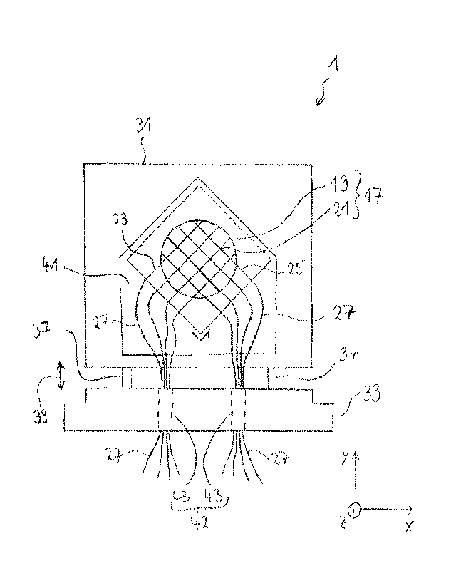
Figure 3 shows the sensor insert 1 in a schematic plan
view in an enlarged illustration. The sensor insert 1
has a grid sensor element 17 comprising a sensor frame
19 and an electrode grid 21. The sensor frame 19
consists of an electrically insulating material, of a
ceramic as an example. The electrode grid 21 has, as an
example, a plurality of transmitting electrodes 23
which are arranged so as to run parallel to one another
along a firstl longitudinal direction in a first plane,
and a plurality of receiving electrodes 25 which are
arranged so as to run parallel to one another along a
second longitudinal direction in a second plane. The
CA 02998821 2018-03-14
WO 2017/059840
PCT/DE2016/100397
- 21 -
first and second plane are parallel to one another, and
the first longitudinal direction forms an angle of 900
with the second longitudinal direction. The grid sensor
element 17 is mounted on the sensor insert such that,
when the sensor insert 1 is held in the insert holder 7
as intended, the first and the second planes are
perpendicular to the flow direction 13 (z direction).
The electrodes of the electrode grid 21 are tensioned
over the circular opening defined by the sensor frame
19. The insert holder 7 and the sensor insert 1 are
formed such that, when the sensor insert 1 is held in
the insert holder 7 as intended, the electrode grid 21
is arranged in the flow path 13.
The sensor insert 1 also has a plurality of connecting
lines 27 for the electrical contacting of the
electrodes 23, 25 of the electrode grid 21.
The sensor insert 1 has an insert element 29. The
configuration of the insert element 29 is illustrated
in figures 4 and 5. The insert element 29 has a holder
section 31 for holding the grid sensor element 17 and a
closure section 33 for closing off the insert opening
15. When the grid sensor system is used as intended,
the grid sensor element 17 is held on the holder
section 31.
The sensor insert 1 and the insert holder 7 are formed
such that, when the grid sensor system is operated as
intended with the sensor insert 1 inserted into the
insert holder 7, the holder section 31 of the insert
element 29 is held in the holder cavity 16, and the
insert opening 15 is closed off by means of the closure
section 33 of the insert element 29 (wherein seals are
able to be provided between the housing 35 which
defines the insert opening 15 and the closure section
31 in a known manner). For example, it may be provided
that the closure section 33 is pressed onto the insert
CA 02998821 2018-03-14
WO 2017/059840
PCT/DE2016/100397
- 22 -
holder 7, or onto the housing 35 which defines the
insert opening 15, by means of screws or other
releasable connections and thus closes off the insert
opening 15 in a fluid-tight manner. It is thus
possible, for example, to provide a plurality of
through bores 36 in the closure section 33 for passing
through screws and corresponding inner threads 38 on
the insert holder 7 for retaining the screws. Thus, the
insert holder 7 and the sensor insert 1 are formed in
particular such that, when the sensor insert 1 is held
in the insert holder 7 as intended, the insert opening
is closed off in a fluid-tight manner by means of
the sensor insert 1.
15 The sensor insert 1 also has a positioning device 37 as
a constituent part of the insert element 29, which is
designed for the variable setting of the positioning of
the holder section 31 relative to the closure section
33. The positioning device 37 is designed for the
variable setting of the spacing which is present
between the holder section and the closure section. By
means of the positioning device 37, the spacing which
is present between the holder section 31 and the
closure section 33 along the insertion direction (y
direction) (when the sensor insert is held in the
insert holder as intended) is adjustable and thus
settable to a desired value. In the present case, the
positioning device 37 is provided by two positioning
screws 37 connected between the holder section 31 and
the closure section 33, by means of which screws the
spacing between the holder section 31 and the closure
section 33 along the y direction is adjustable
(illustrated in figure 3 by the double arrow 39).
The holder section 31 of the insert element 29 has a
holder for holding the grid sensor element 17. As an
example, the holder section 31 has a holder recess 41,
wherein the grid sensor element 17 is held in the
CA 02998821 2018--14
WO 2017/059840
PCT/DE2016/100397
- 23 -
holder recess 41 and is retained in the holder recess
41 by means of a fixing cover (not illustrated) such
that the grid sensor element 17 is arranged and
retained between the bottom of the holder recess 41 and
the fixing cover. Passage openings (not illustrated)
for the passage of the fluid flow which is to be
characterized are formed in the recess bottom of the
holder recess and in the fixing cover.
The sensor insert 1 has a leadthrough device 42 with a
plurality of (as an example: two) fluid-tight
leadthroughs 43 for leading through the connecting
lines 27. Each of the electrodes 23, 25 of the
measuring grid 21 is contacted by one of the connecting
lines 27. Each of the connecting lines 27 is led
through one of the leadthroughs 43 and thus led out of
the holder cavity 16. Those connecting lines 27 by
which the transmitting electrodes 23 are contacted are
arranged so as to run through one of the two
leadthroughs 43. Those connecting lines 27 by which the
receiving electrodes 25 are contacted are arranged so
as to run through the other one of the two leadthroughs
43, and so a plurality of the connecting lines 27 are
led through both of the leadthroughs 43. Consequently,
each of the two leadthroughs 43 is formed as a multiple
leadthrough. The two leadthroughs 43 are formed in the
closure section 33 of the insert element 29. The
leadthroughs 43 are indicated schematically by means of
broken lines in figure 3.
The connecting lines 27 are arranged so as to run
without any tensile stress in the region between the
sensor frame 19 and the leadthrough device 42 or the
leadthroughs 43 assigned to said lines. The connecting
lines 27 thus run without any tensile stress between
the contacting point where they contact the grid
electrode assigned to them and the leadthrough 43
through which they are led.
CA 02998821 2018-03-14
WO 2017/059840
PCT/DE2016/100397
- 24 -
The sensor insert 1 is designed such that none of the
electrodes 23, 25 of the electrode grid 21 (that is to
say neither the transmitting electrodes 23 nor the
receiving electrodes 25) run parallel to the insertion
direction (y direction) (when the sensor insert 1 is
held in the insert holder 7 as intended). The grid
sensor element 17 is held on the sensor insert 1 such
that both the transmitting electrodes 23 and the
receiving electrodes 25 run in the xy plane
perpendicular to the flow direction 13 (when the sensor
insert 1 is held in the insert holder 7 as intended),
wherein both the transmitting electrodes 23 and the
receiving electrodes 25 form an angle of 450 with the
insertion direction (y direction).
The insert holder 7 has a further (closable) opening
(not illustrated) opposite the insert opening 15, which
is able to function as a further insert opening.
Accordingly, the insert holder or the holder cavity is
formed as a through opening which is open on both
sides.
CA 02998821 2018-03-14
WO 2017/059840 PCVDE2016/100397
- 25 -
List of reference signs used
1 Sensor insert
2 Flow guide
3 Inlet line
Outlet line
7 Insert holder
9 Flange of the inlet line
11 Flange of the outlet line
13 Flow path / flow direction
Insert opening
16 Holder cavity
17 Grid sensor element
19 Sensor frame
21 Electrode grid / Measuring grid
23 Transmitting electrodes
Receiving electrodes
27 Connecting lines
29 Insert element of the sensor insert
31 Holder section of the insert element
33 Closure section of the insert element
Housing of the insert holder
36 Through bore
37 Positioning device
38 Inner thread
39 Variable spacing between holder section and
closure section
41 Holder recess
42 Leadthrough device
43 Leadthrough / multiple leadthrough