Note: Descriptions are shown in the official language in which they were submitted.
CA 02999409 2018-03-21
CUTTING METHOD USING A STAMPING PRESS
Technical Field
[0001] The present disclosure relates to a cutting method that uses a stamping
press to shear
and cut a workpiece configured from a first metal sheet and a second metal
sheet joined at a
weld portion, so as to cut across the weld portion.
Background Art
[0002] Shearing, such as when blanking or piercing a thin metal sheet using a
press, is
widely employed in the processing of electrical devices, automobile
components, and the like
due to shearing being highly productive and having low machining costs.
However, when
such shearing is applied to high strength steel sheets with a tensile strength
exceeding 1000
MPa, there is a problem that the residual stress is high at edges of blanks,
hydrogen
embrittlement cracking (also referred to as season cracking or delayed
fracture) is liable to
occur, and there is a deterioration in fatigue properties.
[0003] Moreover, it is known that when a workpiece configured from the same
type or
different types of metal sheet joined by welding is sheared, the hydrogen
embrittlement
resistance and fatigue properties of the sheared faces of the weld portion and
the heat-affected
zone (referred to below as "HAZ portion") deteriorate.
[0004] A die roll formed by the workpiece being pressed in by the punch, a
shear face
formed by the workpiece being drawn into a gap between the punch and die
(referred to
below simply as "clearance") and locally extended, a fracture face formed by
the workpiece
fracturing partway through shear face forming, and a burr generated on the
blanking back face
of the workpiece, are present on the blank edge faces of the workpiece after
blanking.
[0005] Normally, the clearance and tool shape are adjusted so as to achieve
prescribed
amounts of die roll, shear face, fracture face, and burr generation at the
blank edge faces, or to
achieve improvements to the edge face properties after processing with respect
to stretch
flange formability, fatigue properties, hydrogen embrittlement resistance, and
the like.
[0006] For example, Japanese Patent Application Laid-Open (JP-A) No. 2006-
224151
(referred to below as Patent Document 1) discloses being able to reduce work
hardening and
residual tensile stress at edge faces after processing by using tools
including curved blades in
which the tip portion of a cutting blade portion of the punch and/or the die
has a protruding
1
CA 02999409 2018-03-21
profile, with a predetermined radii of curvature and blade shoulder angles,
and with a
clearance of 25% or less.
[0007] Moreover, it is reported in "The proceedings of Japanese Joint
Conference for the
Technology of Plasticity", volume 63, page 338 (referred to below as Non-
Patent Document
1), that the residual tensile stress of blanking faces is reduced by shearing
under high
compressional stress with a clearance to thickness ratio of not greater than
1%. A piercing
method having excellent burring properties is introduced in JP-A No. 2014-
111283 (referred
to below as Patent Document 2). In this method, the angle between a direction
of excellent
ductility and a blade edge direction of a wedge shaped punch was set at not
greater than 10
degrees.
SUMMARY OF INVENTION
Technical Problem
[0008] The hydrogen embrittlement properties and fatigue properties can be
improved by
controlling shearing so as to reduce residual stress at sheared faces (see,
for example, Patent
Document 1 and Non-Patent Document 1). However, it is difficult to produce
blanking
faces having uniform end face characteristics when formed by the method of
Patent
Document 1. Namely, in cases in which the punch shape has a uniform cutting
line direction,
cracking is liable to occur at weld portions and heat-affected zones where
residual stress is
high and ductility and toughness is low at the sheared faces.
[0009] However, in cases in which the clearance to thickness ratio is not
greater than 1%, as
in the method of Non-Patent Document 1, galling occurs due to slight punch
misalignment.
Moreover, there is a problem that when the clearance changes due to wear at
the side faces of
the punch and die, the residual stress is increased at sheared faces, and
sufficient improvement
effect for fatigue properties and sufficient improvement effect for hydrogen
embrittlement
resistance is no longer obtainable.
[0010] An object of the present disclosure is to provide a cutting method
using a stamping
press that enables a reduction to be made in residual stress at sheared faces
of at least one of a
weld portion or a heat-affected zone of a workpiece.
Solution to Problem
[0011] A cutting method using a stamping press according to a first aspect of
the present
disclosure is employed on a workpiece that is configured from a first metal
sheet and a second
metal sheet joined at a weld portion and that has a heat-affected zone around
the weld portion.
2
The cutting method includes positioning the workpiece at a position relative
to a punch that
includes a projecting portion projected more toward the workpiece than a fiat
portion of the
punch such that the projecting portion starts to cut at least at one out of
the heat-affected zone
or the weld portion before the flat portion cuts the workpiece, and cutting
the workpiece by
moving the punch and a die relative to each other at the positioned position
so as to shear
across the weld portion on the workpiece.
[0012] According to the present disclosure, residual stress can be reduced at
sheared faces of
the weld portion or the heat-affected zone of a workpiece.
[0012a] Another aspect of the present disclosure relates to a cutting method
using a stamping
press. The cutting method comprises: for a workpiece comprising a first metal
sheet and a
second metal sheet joined at a weld portion, and a heat-affected zone around
the weld portion,
positioning the workpiece at a position relative to a punch, the punch
including a projecting
portion that projects further toward the workpiece than a flat portion of the
punch, such that
the projecting portion starts to cut one or more of the heat-affected zone and
the weld portion,
before the flat portion cuts the workpiece; and cutting the workpiece by
moving the punch
and a die relative to each other at the position at which the workpiece is
positioned, so as to
shear across the weld portion of the workpiece. The projecting portion of the
punch has a
wedge shape with a width dimension that progressively narrows towards the
projecting
direction, with an angle formed between one face at one width direction side
of the projecting
portion and another face at another side of the projecting portion of from 10
degrees to 170
degrees. And the cutting is performed with the width direction oriented in a
direction along
which the first metal sheet and the second metal sheet are arrayed.
BRIEF DESCRIPTION OF DRAWINGS
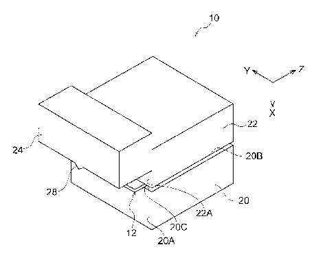
[0013] Fig. 1 is a schematic perspective view illustrating a cutting machine
of a first
exemplary embodiment.
Fig. 2 is a schematic front view of a cutting machine of the first exemplary
embodiment, as viewed along the Z direction of Fig. I.
Fig. 3 is a schematic side view of a cutting machine' of the first exemplary
embodiment, as viewed along the Y direction of Fig. 1.
3
CA 2999409 2019-12-20
Fig. 4 is a schematic top view of a cutting machine of the first exemplary
embodiment, as viewed along the X direction of Fig. 1.
Fig. 5 is a schematic front view illustrating a punch of the first exemplary
embodiment, as viewed along the Z direction of Fig. 1.
Fig. 6 is an enlarged diagram of Fig. 5 to explain a relationship between a
projecting
portion of the punch according to the first exemplary embodiment and a
workpiece.
Fig. 7 is an enlarged diagram of Fig. 6 to explain a projecting portion
according to
the first exemplary embodiment.
Fig. 8 is a schematic side view to explain a projecting portion according to
the first
exemplary embodiment, as viewed along the Y direction of Fig. I.
Fig. 9A is a diagram similar to Fig. 6, and is used to explain when
positioning of a
workpiece is at a second metal sheet side with respect to a punch.
Fig. 9B is a diagram similar to Fig. 6, and is used to explain when
positioning of a
workpiece is at a first metal sheet side with respect to a punch.
Fig. 10 is a schematic front view to explain a state in which a projecting
portion of a
punch according to the first exemplary embodiment shears a portion of a first
heat-affected
zone, a weld portion, and a portion of a second heat-affected zone.
3a
CA 2999409 2019-07-11
CA 02999409 2018-03-21
Fig. 11 is a schematic front view to explain a state in which a projecting
portion of a
punch according to the first exemplary embodiment shears a portion of a weld
portion and a
second heat-affected zone.
Fig. 12 is a schematic front view to explain the projecting portion of a punch
according to the first exemplary embodiment shearing a portion of the second
heat-affected
zone.
Fig. 13 is a schematic front view to explain a shape of a projecting portion
according
to a second exemplary embodiment.
Fig. 14 is a schematic front view to explain a shape of a projecting portion
according
to a third exemplary embodiment.
Fig. 15 is a schematic front view to explain a shape of a projecting portion
according
to a fourth exemplary embodiment.
Fig. 16 is a schematic front view to explain a shape of a projecting portion
according
to a fifth exemplary embodiment.
Fig. 17 is a schematic front view to explain a shape of a projecting portion
according
to a sixth exemplary embodiment.
Fig. 18 is a schematic front view to explain a shape of a projecting portion
according
to a seventh exemplary embodiment.
Fig. 19 is a schematic front view to explain a shape of a projecting portion
according
to an eighth exemplary embodiment.
Fig. 20 is a graph illustrating residual stress at a second boundary against
distance to
the second boundary from a center of a cutting edge of a projecting portion.
DESCRIPTION OF EMBODIMENTS
[0014] First, the present inventors investigated shearing a workpiece
configured from two
types of rolled metal sheet welded and joined together, by shearing with a
flat punch and die,
and investigated the residual stress at the sheared faces. As a result, it was
found that
residual tensile stress similar to, or greater than, that of other portions
(general portions)
remained at weld portions and heat-affected zones.
[0015] At the weld portions and heat-affected zones, as a result of the heat
input during
welding, crystal grains increased in grain size and ductility and toughness
deteriorated.
There was accordingly a concern that cracks might readily occur at sheared
faces when tensile
stress from the shearing remains at the sheared face (blanking faces). Thus,
cracks can be
4
CA 02999409 2018-03-21
suppressed from occurring at the sheared faces and hydrogen embrittlement
cracking can be
suppressed by reducing the tensile stress remaining at the sheared faces of at
least part of the
weld portions or heat-affected zones.
[0016] The present inventors have then discovered that the generation of
cracks and the
generation of hydrogen embrittlement cracking can be effectively suppressed by
providing a
projecting portion projected from a punch, and shearing the workpiece by
inserting the
projecting portion into a region of at least part of a weld portion or a heat-
affected zone of the
workpiece before a flat portion. Next, description follows regarding a cutting
method using
a stamping press to implement this discovery.
[0017] First Exemplary Embodiment
Description follows regarding a first exemplary embodiment, with reference to
the
drawings.
[0018] Fig. 1 illustrates a cutting machine 10 for executing a cutting method
using a
stamping press according to the present exemplary embodiment. Fig. 2 is a
front face view
of the cutting machine 10 illustrated in Fig. 1. Fig. 3 illustrates a side
face of the cutting
machine 10 illustrated in Fig. 1. Moreover, Fig. 4 illustrates an upper face
of the cutting
machine 10 illustrated in Fig. 1. Fig. 5 illustrates a front face of a punch
24. In each of the
drawings, an X axis, a Y axis, and a Z axis illustrate three mutually
orthogonal axes.
[0019] The cutting machine 10, for example as illustrated in Fig. 1 to Fig. 5,
is a device for
cutting a sheet shaped workpiece 12 by shearing with the punch 24 and a die
20. Note that
for ease of explanation, details concerning a configuration of the cutting
machine 10 will be
described later. The workpiece 12 to be cut is, for example as illustrated in
Fig. 2, a metal
sheet configured from a first metal sheet 14 and a second metal sheet 16 that
have been
formed into a sheet shape by rolling, and have been joined by welding together
abutting
portions thereof. A weld portion 18 is formed at a portion between the first
metal sheet 14
and the second metal sheet 16, this being the abutting portion. Heat-affected
zones 30, 32
are formed around the weld portion 18 (at both sides of the weld portion 18 in
the Y direction).
For ease of explanation, details concerning a configuration of the weld
portion 18, and of the
heat-affected zones 30, 32 will be described later.
Fusion welding, such as arc welding or the like, pressure welding, such as
resistance
welding including upset welding and flash welding, may, for example, be
employed to weld
the abutting portions together.
CA 02999409 2018-03-21
[0020] In the workpiece 12, there is no limitation to welding the abutting
portions and, for
example, the workpiece 12 may be a metal plate configured from the first metal
sheet 14 and
the second metal sheet 16 joined by various joining methods, such as mash seam
welding,
friction stir welding, and the like.
Moreover, irrespectively to the welding method, the first metal sheet 14 and
the
second metal sheet 16 may be metal sheets of the same type of metal or metal
sheets of
different types of metal. Tailor welded blanks (TWBs) of different types of
metal sheet
joined by welding are press stock tailored as desired for strength, rust-
proofing, and the like.
[0021] Stock for the workpiece 12 is not limited to steel sheet, and examples
include iron,
copper, zinc, tin, aluminum, titanium, magnesium, and alloys based thereon.
There
thickness dimension T12 of the workpiece 12 is not limited to a particular
thickness, so long
as it is a thickness capable of being sheared. Moreover, the thicknesses of
the first metal
sheet 14 and the second metal sheet 16 may be different from each other.
[0022] Note that in cold shearing, the thickness dimension T12 of the
workpiece 12
preferably does not exceed 6.0 mm from the perspective of preserving product
dimensional
precision. In particular, the thickness dimension T12 of the workpiece 12
preferably does
not exceed 3.0 mm in cases in which a high degree of product dimensional
precision is
demanded.
However, when the thickness dimension T12 of the workpiece 12 is too thin,
then
joining by welding becomes unstable, and so the thickness dimension T12 of the
workpiece
12 is preferably 0.1 mm or greater. Moreover, the thickness dimension T12 is
more
preferably 0.5 mm or greater.
[0023] The workpiece 12 is, for example, employed in automobiles, consumer
electricals,
construction structures, ships, bridges, construction machinery, various
plant, or the like.
[0024] Moreover, examples serving as the workpiece 12 include cold rolled
sheets and the
like that, after shearing in blanking or piercing using a press, sheared
portions thereof are
subjected to hole widening or to flange raising.
[0025] As illustrated in Fig. 6, the weld portion 18 and the heat-affected
zones 30, 32
described above are formed in the workpiece 12. The weld portion 18 is a
portion where the
first metal sheet 14 and the second metal sheet 16 that have melted have then
re-solidified.
The heat-affected zones 30, 32 are structures in the workpiece 12 that have
not been melted
by heat applied when forming the weld portion 18, but where changes have
occurred in metal
6
CA 02999409 2018-03-21
(metallurgical) properties, mechanical properties, or the like (see, for
example, the JIS
standard on welding terminology (JIS Z 3001 no. 11202)).
[0026] For ease of explanation, in the present exemplary embodiment, the heat-
affected zone
of the first metal sheet 14 on an S1 side of the weld portion 18 is referred
to as a first
heat-affected zone 30, and the heat-affected zone of the second metal sheet 16
on the other S2
side thereof is referred to as a second heat-affected zone 32.
[0027] Let the coordinate in the Y axis direction of an edge 12A at the S I
side of the
workpiece 12 be XO, and a distance from XO to a first boundary 34 between the
first
heat-affected zone 30 and the weld portion 18 be Xl. Moreover, let a distance
from XO to a
second boundary 36 between the second heat-affected zone 32 and the weld
portion 18 be X2.
[0028] Next, description follows regarding a detailed configuration of the
cutting machine
10. The cutting machine 10 includes, for example as illustrated in Fig. Ito
Fig. 4, a die 20
having a cuboidal shape. The workpiece 12 is placed on an upper face of the
die 20. A
stopper 22 is disposed above the die 20. The stopper 22 is also formed in a
cuboidal shape
substantially similar to that of the die 20. The stopper 22 is disposed such
that a front face
22A, which is the face on the Z axis direction side, is positioned in the Z
axis direction in the
same flat plane as a front face 20A of the die 20. The stopper 22 is raised or
lower by, for
example, a raising and lowering mechanism, not illustrated in the drawings,
and fixed so as to
press the workpiece 12, which has been set on the upper face of the die 20,
from above.
[0029] The punch 24 is provided on the front face 22A side of the stopper 22.
The punch
24 is formed in a cuboidal shape, and is set with a width dimension in the Y
axis direction that
is substantially the same dimension as the width dimension of the stopper 22
and the die 20.
The punch 24 is driven by a drive mechanism, not illustrated in the drawings,
in the up-down
direction, which is the X axis direction, along the front face 22A of the
stopper 22 and the
front face 20A of the die 20. Thus, in a state in which the workpiece 12 is
clamped between
the die 20 and the stopper 22, the punch 24 is thereby configured so as to be
able to cut an
extending portion of the workpiece 12 extending out from the die 20 by a
shearing action of
the punch 24 and the die 20.
[0030] The X axis direction lower face of the punch 24 is formed flat, as
illustrated in Fig. 5.
This flat lower face is a flat portion 26. A projecting portion 28 is formed
at a center of the
flat portion 26 in the width direction, which is the Y axis direction
(illustrated by the punch
center line PC in Fig. 7 in the present exemplary embodiment), with the
projecting portion 28
projecting toward the workpiece 12 side. The workpiece 12 is, for example as
illustrated in
7
CA 02999409 2018-03-21
Fig. 7 and Fig. 8, set on the die 20 as described below, so as to be disposed
below the flat
portion 26 in the X axis direction. As illustrated in Fig. 8, the projecting
portion 28 forms a
projection that extends in the front-rear direction, which is the Z axis
direction. Note that the
punch 24 may be provided with plural of the projecting portions 28.
[0031] The projecting portion 28 is, for example as illustrated in Fig. 7,
formed in a wedge
shape such that a width dimension W28' in the Y axis direction narrows on
progression in the
projecting direction, which is downward in the X axis direction, from base
ends Xa, Xc on the
flat portion 26 side, which is the X axis direction upper side. Namely, when
sectioned
orthogonally to the movement direction of the punch 24 (the X axis direction),
the projecting
portion 28 has a cross-sectional area that decreases on progression from a
base end portion on
the flat portion 26 side toward a cutting edge 28A at the leading end of the
projecting portion
28.
[0032] This reference to a wedge shape means a blade having one end that is
thick and that
thins on progression toward the other end. In the present exemplary
embodiment, the cutting
edge of the blade may be pointed or may be flat.
[0033] The projecting portion 28 that is formed in the wedge shape includes
one face 28B
formed on a face on one Y axis direction side, and another face 28C formed on
a face on the
other side. The one face 28B and the other face 28C are configured by flat
faces that are
inclined toward the punch center line PC side on progression from the flat
portion 26 toward a
tip Xb side. The "punch center line PC" referred to here is an imaginary line
that extends
along the X axis direction so as to pass through a center of the punch 24 in
the Y axis
direction. Moreover, the "tip Xb" is a location at the Y axis direction center
of the cutting
edge 28A, and is positioned on the punch center line PC. The one face 28B and
the other
face 28C are linked by the flat cutting edge 28A on the tip Xb side of the
projecting portion
28.
[0034] A front end face 28D of the projecting portion 28 is, for example as
illustrated in Fig.
8, formed so as to be contiguous downward in the X axis direction from a front
face 24A of
the punch 24. The front end face 28D has an isosceles triangle shape (see Fig.
7) projecting
downward in the X axis direction as viewed along the Z axis direction.
Moreover, similarly,
a rear end face 28E of the projecting portion 28 is also formed so as to
contiguous to a rear
face 24B of the punch 24. Moreover, the shape is an equilateral triangular
shape projecting
downward in the X axis direction as viewed along the Z axis direction.
8
CA 02999409 2018-03-21
[0035] It is sufficient that the projecting portion 28 projects from the flat
portion 26 at least
downward in the X axis direction. Due to adopting such a configuration, the
projecting
portion 28 starts to cut the workpiece 12 before the flat portion 26 cuts the
workpiece 12, as
described below. The present invention is able to obtain the advantageous
effect of reducing
residual stress at the sheared faces by adopting such a configuration.
[0036] Moreover, in order to obtain the advantageous effect of reducing
residual stress at the
sheared faces, for example as illustrated in Fig. 7, a projection dimension H
of the projecting
portion 28 from the flat portion 26 is preferably not less than 10% of the
thickness dimension
T12 of the workpiece 12 to be cut (see Fig. 6). Furthermore, the projection
dimension H is
more preferably not less than 50% of the thickness dimension T12 of the
workpiece 12.
[0037] Note that although a greater advantageous effect of reducing residual
stress at the
sheared faces is obtained the larger the projection dimension H referred to
here, an upper limit
for the projection dimension H is naturally limited so as to avoid impinging
on the set
workpiece 12 when the punch 24 is in an upper position.
[0038] Moreover, preferably the following parameters are satisfied in order to
prevent
damage to the cutting edge 28A. Namely, an angle a formed between the one face
28B and
the other face 28C of the projecting portion 28 is preferably 10 degrees or
greater. This is
because there is a concern regarding stress concentrating at the cutting edge
28A and damage
to the cutting edge 28A occurring if the angle a is less than 10 degrees.
[0039] Moreover, the angle a is preferably not greater than 170 degrees from
the perspective
of being able to concentrate the shear stress, and is more preferably not
greater than 120
degrees. Moreover, the angle a is even more preferably not greater than 80
degrees.
[0040] A positional relationship between the workpiece 12 and the projecting
portion 28,
and a width dimension W28 between the base end Xa and the base end Xc on the
flat portion
26 side of the projecting portion 28 is determined as indicated below.
[0041] When the tip Xb abuts and shears the Y axis direction center of the
weld portion 18,
the following parameters for the positional relationship between the workpiece
12 and the
projecting portion 28 enable the advantageous effect of reducing residual
stress at the sheared
faces to be obtained for the weld portion 18 and the heat affected zones 30,
32.
[0042] The width dimension W28 is determined based on the width dimension W18
of the
weld portion 18. First, as illustrated in Fig. 7, let the base end Xa at the
intersection of the
one face 28B of the projecting portion 28 and the flat portion 26 be a first
base end Xa, and let
the base end Xc at the intersection of the other face 28C of the projecting
portion 28 and the
9
CA 02999409 2018-03-21
flat portion 26 be a second base end Xc. Moreover, let the distance from the
first base end
Xa to the punch center line PC be a first width dimension Wl, and let the
distance from the
second base end Xc to the punch center line PC be a second width dimension W2.
Let the
total width dimension of the first width dimension W1 and the second width
dimension W2
be the width dimension W28. In the present exemplary embodiment, the width
dimension
W28 is larger than the width dimension W18 of the weld portion 18, for example
as
illustrated in Fig. 6 (W28 = (W1 + W2) > W18).
[0043] In order to maintain end face properties of shear faces other than at
the weld portion
18 and to obtain the advantageous effect of reducing residual stress at the
sheared faces,
preferably setting is performed within a range such that a < 170 degrees and
W28 = (W1 +
W2) < 5 x T12 (the thickness dimension T12 of the workpiece 12). More
preferably, the
width dimension W28 at the base end portion of the projecting portion 28 is
set within a range
such that a < 120 degrees and W28 = (W1 + W2) < 5 x T12 (the thickness
dimension T12 of
the workpiece 12).
[0044] The wedge shaped cutting edge 28A is, for example as illustrated in
Fig. 7, formed
flat. Such a cutting edge 28A has a rectangular shaped face as viewed along
the X axis
direction from the lower side. If the tip portion of the cutting edge 28A is
an acute angle
then there is a concern regarding damage from chipping occurring due to stress
concentrating
at the cutting edge 28A. Thus the cutting edge 28A is made flat, enabling
damage to the
cutting edge 28A to be prevented and the punch 24 to be protected.
[0045] The width dimension 1-128 of the cutting edge 28A in the Y axis
direction is
preferably not less than 1% of the thickness dimension T12 of the workpiece 12
(see Fig. 6).
Making the width dimension H28 not less than 1% of the thickness dimension T12
prevents
excessive stress concentration at the cutting edge 28A. This thereby enables
damage to the
cutting edge 28A to be prevented. Moreover, the width dimension W28 at the
base end
portion of the projecting portion 28 is preferably smaller than the total
width of the width
dimension WI 8, the width dimension W30, and the width dimension W32. Making
the
width dimension W28 such a value means that the projecting portion 28 does not
overlap with
the entire region of the weld portion 18 and the heat affected zones 30, 32 in
the width
direction when the projecting portion 28 shears the workpiece 12. This enables
the
advantageous effect of reducing residual stress at the shear faces to be
reliably obtained at
least in one region of the weld portion 18 and the heat affected zones 30, 32.
CA 02999409 2018-03-21
[0046] Moreover, the shape of the cutting edge 28A of the projecting portion
28 may be a
curved shape (rounded shape) as described below with reference to Fig. 15 and
Fig. 16.
Making the cutting edge 28A a curved shape prevents a concentration of stress,
enabling
damage to the cutting edge 28A to be prevented.
[0047] A clearance 38, for example as illustrated in Fig. 8, where a gap is
formed between
the rear face 24B of the punch 24 and the front face 20A of the die 20 is
preferably a
dimension from 0.5% to 25% of the thickness dimension T12 of the workpiece 12
as
expressed in the following.
[0048] If the clearance 38 is less than 0.5% of the thickness dimension T12 of
the workpiece
12 then there is a concern regarding damage to the tip portion of the
projecting portion 28 due
to chipping occurring, and so the clearance 38 is preferably not less than
0.5% of the
thickness dimension T12 of the workpiece 12. The clearance 38 is more
preferably not less
than 1.0% thereof.
[0049] However, if the clearance 38 exceeds 25% of the thickness dimension T12
of the
workpiece 12, then curving of the workpiece 12 increases, with burr liable to
be generated.
The clearance 38 is accordingly 25% of the thickness dimension T12 of the
workpiece 12 or
less. The clearance 38 is more preferably 15% thereof or less.
[0050] When using the cutting machine 10 to execute the cutting method using a
stamping
press of the present exemplary embodiment, the workpiece 12 is set on an upper
face 20B of
the die 20, the workpiece 12 is slid in the Z axis direction such that a
portion to be sheared off
juts out from the die 20, with a shear position aligned with a front edge 20C
of the die 20
(setting process).
[0051] When this is performed, first, as illustrated in Fig. 9A, the workpiece
12 is positioned
with respect to the punch 24 such that the first base end Xa of the projecting
portion 28 is
positioned further to the first metal sheet 14 side than a boundary 32A
between the second
heat-affected zone 32 of the second metal sheet 16 and a general portion 16A
thereof
Reference in the present exemplary embodiment to a "general portion" indicates
a portion of
the workpiece 12 that is not affected by welding* namely a portion on the Y
axis direction
outside of the heat-affected zones. Thereby, the projecting portion 28 start
to cut the
workpiece 12 at least at one out of the weld portion 18 or at least one of the
heat affected
zones 30, 32 before the flat portion 26 of the punch 24 cuts the workpiece 12.
Note that
reference in the present exemplary embodiment to "starting cutting" means
contact between
the punch 24 and the workpiece 12 (generation of die roll).
11
CA 02999409 2018-03-21
Similarly, as illustrated in Fig. 9B, the workpiece 12 is positioned with
respect to the
punch 24 such that a second base end Xe of the punch 24 is positioned further
to the second
metal sheet 16 side than a boundary 30A between the first heat-affected zone
30 and a general
portion 14A. Namely, it is sufficient to position the workpiece 12 with
respect to the punch
24 such that one out of the first base end Xa or the second base end Xc is
positioned inside a
range from the boundary 30A to the boundary 32A of the workpiece 12.
[0052] It is known that in cases in which plural of the workpieces 12 are
formed by welding
the metal sheets 14,16, which have the same combination of materials as each
other, under the
same respective conditions, the width dimensions of the weld portion 18 and
the heat affected
zones 30, 32 are substantially the same dimension in the respective workpieces
12.
[0053] Thus, the position in the Y axis direction and the width dimension of
the weld
portion 18 and the heat affected zones 30, 32 may be measured in advance for a
representative
sample of the workpieces 12 to be cut. The results of such measurement may
then be
employed to position the Y axis direction of the workpiece 12 with respect to
the projecting
portion 28 of the punch 24.
[0054] In such a positioned state, the drive mechanism is operated to lower
the punch 24 and
to move the punch 24 relative to the die 20. The workpiece 12 is then cut by
shearing so as
to cut the workpiece 12 across the weld portion 18 (cutting process). Note
that the die 20
may be moved with respect to the punch 24.
[0055] In this cutting process, the cutting edge 28A of the projecting portion
28 contacts the
workpiece 12 fixed by the die 20 and the stopper 22. When this occurs, by
positioning the
workpiece 12 in advance such that one out of the first base end Xa or the
second base end Xc
is positioned between the boundary 30A and the boundary 32A of the workpiece
12, the
projecting portion 28 is inserted at least at one location of the heat
affected zones 30, 32 and
the weld portion 18 when the punch 24 is lowered. The projecting portion 28
then shears the
workpiece 12 as stress acts on the at least one location of the heat affected
zones 30, 32 and
the weld portion 18. When this occurs, due to stress concentrating at the
cutting edge 28A
of the projecting portion 28, the cutting edge 28A is inserted into the
workpiece 12 while
pressing downward on the workpiece 12 in the X axis direction. Although the
region of the
workpiece 12 in contact with the projecting portion 28 is sheared by the
stress acting
downward in the X axis direction through the projecting portion 28, the stress
acting in the
vicinity of the shearing location is limited and there is only a small amount
of plastic
deformation. The regions of the workpiece 12 sheared by the projecting portion
28 are
12
CA 02999409 2018-03-21
thereby progressively sheared in a state restrained by the workpiece 12 at the
periphery
thereof. Thus, the generation of ductile fracture cracks is delayed in the
regions in contact
with the projecting portion 28, extending the shear face region, and reducing
residual tensile
stress. In this manner, the projecting portion 28 shears the workpiece 12
before the flat
portion 26 of the punch 24 cuts the workpiece 12.
[0056] Then, as the punch 24 is lowered, the flat portion 26 abuts the
workpiece 12 and
presses the workpiece 12. Thereby, the workpiece 12 curves by deforming
downward under
the stress generated by the pressing, and the workpiece 12 receives a shearing
action from the
flat portion 26 of the punch 24 and the die 20 while being in a curved state,
and is cut.
[0057] When this occurs, a portion of the workpiece 12 is sheared by the
projecting portion
28 before the flat portion 26 cuts the workpiece 12 as a whole, extending the
shear face region.
Thus, in comparison to cases in which the workpiece 12 is cut by the flat
portion 26 of the
punch 24 alone, the tensile stress remaining in at least one location of the
heat affected zones
30, 32 and the weld portion 18 during the shearing can be greatly reduced. As
a result, the
generation of hydrogen embrittlement cracking and the generation of fatigue
cracks at the
sheared faces after shearing can be suppressed.
[0058] Thus, for example, even for high strength steel sheets with a tensile
stress exceeding
1000 MPa where there is liable to be high residual stress at the sheared
faces, and in tailor
welded blanks (TWBs), the generation of hydrogen embrittlement cracking and
the generation
of fatigue cracks can be suppressed.
[0059] Moreover, for example, even in cases in which there is a somewhat large
clearance
38 between the punch 24 and the die 20, such as, for example, 10% or greater,
sheared faces
can be formed that have excellent tensile properties, fatigue properties, and
hydrogen
embrittlement resistance.
[0060] The width dimension W28 at the base end of the projecting portion 28 is
set larger
than the width dimension W18 of the weld portion 18. Thus, for example as
illustrated in
Fig. 10, the projecting portion 28 can cut the weld portion 18 and at least a
portion of the first
heat-affected zone 30 adjacent to the weld portion 18 and at least a portion
of the second
heat-affected zone 32 adjacent to the weld portion 18 before the flat portion
26 cuts the
workpiece 12. This enables tensile stress remaining at the sheared faces in
the weld portion
18, the first heat-affected zone 30, and the second heat-affected zone 32 to
be reduced,
enabling the generation of hydrogen embrittlement cracking and the generation
of fatigue
cracks to be effectively suppressed.
13
CA 02999409 2018-03-21
[0061] Note that the residual stress at sheared faces can be reduced so long
as the projecting
portion 28 cuts at least a portion of the weld portion 18, or the first heat-
affected zone 30, or
the second heat-affected zone 32 before cutting by the flat portion 26,
enabling the generation
of hydrogen embrittlement cracking and the generation of fatigue cracks to be
suppressed.
[0062] For example, as illustrated in Fig. 11, certainty that the weld portion
18 and the
second heat-affected zone 32 are sheared first is achieved by positioning the
workpiece 12
such that the center of the cutting edge 28A of the projecting portion 28 is
aligned with the
second boundary 36 between the weld portion 18 and the second heat-affected
zone 32. The
residual stress at sheared faces is accordingly reduced, enabling the
generation of fatigue
cracks at the second boundary 36 to be suppressed.
[0063] Moreover, for example as illustrated in Fig. 12, by the projecting
portion 28 of the
punch 24 shearing a portion of, for example, the second heat-affected zone 32
before cutting
by the flat portion 26, the residual stress is reduced at the sheared faces of
the second
heat-affected zone 32, enabling the generation of fatigue cracks to be
suppressed.
[0064] The projection dimension H of the projecting portion 28 from the flat
portion 26 is
set to not less than 50% of the thickness dimension T12 of the workpiece 12 to
be cut. The
shearing effect of the projecting portion 28 is thereby raised.
[0065] Note that in the present exemplary embodiment, and in a second
exemplary
embodiment to an eighth exemplary embodiment explained below, although the
projection
dimension H is set to not less than 50% of the thickness dimension T12, some
residual stress
reduction effect is still obtained at the sheared faces due to the projecting
portion 28 so long
as the projection dimension H is not less than 10% of the thickness dimension
T12.
[0066] Moreover, the angle a formed between the one face 28B and the other
face 28C of
the projecting portion 28 is set to not less than 10 degrees, so as to prevent
damaging the
cutting edge 28A. Moreover, the angle a is set to from 10 degrees to 80
degrees. This
enables the width dimension W28 to be secured at the base end of the
projecting portion 28
while suppressing damage to the cutting edge 28A.
[0067] Note that in the present exemplary embodiment, and in a second
exemplary
embodiment to an eighth exemplary embodiment explained below, although the
angle a is set
from 10 degrees to 80 degrees, there is no limitation thereto. For example,
the upper limit to
the angle a may be set to not greater than 120 degrees, or to not greater than
170 degrees.
[0068] Moreover, in the present exemplary embodiment, and in a second
exemplary
embodiment to an eighth exemplary embodiment explained below, although the
projecting
14
CA 02999409 2018-03-21
portion 28 is configured with a wedge shape so as to facilitate insertion of
the cutting edge
28A into the workpiece 12, there is no limitation to such a shape. Some
residual stress
reduction effect can still be obtained at the sheared faces even if the
projecting portion 28 is
configured, for example, in a rectangular shape.
[0069] Second Exemplary Embodiment
Fig. 13 is a diagram illustrating a second exemplary embodiment of the present
disclosure. Portions that are the same or equivalent to those of the first
exemplary
embodiment are appended with the same reference signs and description thereof
is omitted.
Only portions that differ from those of the first exemplary embodiment are
described.
[0070] Namely, in the present exemplary embodiment, the shape of a projecting
portion 28
differs from that of the first exemplary embodiment. In the projecting portion
28 according
to the present exemplary embodiment, a first width dimension Wl, from a first
base end Xa at
the intersection between one face 28B and a flat portion 26 to a punch center
line PC, is set
shorter than a second width dimension W2, from the punch center line PC to a
second base
end Xc at the intersection between another face 28C and the flat portion 26
(W1 <W2).
[0071] In such cases, the position where suppression of hydrogen embrittlement
cracking is
desired (a position where hydrogen embrittlement cracking is anticipated to be
the most
extreme) is preferably disposed, sheared, and cut at the center of a cutting
edge 28A of the
projecting portion 28.
[0072] This enables similar advantageous effects to be obtained to those of
the first
exemplary embodiment even in cases in which the first width dimension WI and
the second
width dimension W2 differ from each other.
[0073] Third Exemplary Embodiment
Fig. 14 is a diagram illustrating a third exemplary embodiment of the present
disclosure. Portions that are the same or equivalent to those of the first
exemplary
embodiment are appended with the same reference signs and description thereof
is omitted.
Only portions that differ from those of the first exemplary embodiment are
described.
[0074] Namely, in the present exemplary embodiment, the shape of a projecting
portion 28
differs from that of the first exemplary embodiment. The projecting portion 28
according to
the present exemplary embodiment is configured with curved faces in which one
face 28B
and another face 28C are recessed inward, and an acute cutting edge 28A is
formed.
[0075] The present exemplary embodiment also enables similar advantageous
effects to be
obtained to those of the first exemplary embodiment. Moreover, with the
projecting portion
CA 02999409 2018-03-21
28, although residual stress is reduced at positions in the vicinity of the
tip of the cutting edge
28A and the generation of hydrogen embrittlement cracking and the generation
of fatigue
cracks can be effectively suppressed, there is a large deterioration in
effectiveness at positions
way from the tip.
[0076] Fourth Exemplary Embodiment
Fig. 15 is a diagram illustrating a fourth exemplary embodiment of the present
disclosure. Portions that are the same or equivalent to those of the first
exemplary
embodiment are appended with the same reference signs and description thereof
is omitted.
Only portions that differ from those of the first exemplary embodiment are
described.
[0077] Namely, in the present exemplary embodiment, the shape of the
projecting portion 28
is different from that of the first exemplary embodiment. The projecting
portion 28
according to the present exemplary embodiment is configured by curved faces in
which one
face 2811 and another face 28C bulge outward, and a cutting edge 28A at the
tip of the
projecting portion 28 is configured by a curved face.
[0078] The present exemplary embodiment also enables similar advantageous
effects to be
obtained to those of the first exemplary embodiment.
Moreover, an effect to prevent damage at the cutting edge 28A can be enhanced.
Furthermore, a more uniform residual tensile stress reduction effect is
obtained within the
range of the vvidth dimension W28 (W28 = W1 + W2) at the base end of the
projecting
portion 28.
[0079] Fifth Exemplary Embodiment
Fig. 16 is a diagram illustrating a fifth exemplary embodiment of the present
disclosure. Portions that are the same or equivalent to those of the first
exemplary
embodiment are appended with the same reference signs and description thereof
is omitted.
Only portions that differ from those of the first exemplary embodiment are
described.
[0080] Namely, in the present exemplary embodiment, the shape of the
projecting portion 28
is different from that of the first exemplary embodiment. The projecting
portion 28
according to the present exemplary embodiment has a cutting edge 28A at the
tip configured
by a curved face that projects toward the tip side and is rounded.
[0081] The present exemplary embodiment also enables similar advantageous
effects to be
obtained to those of the first exemplary embodiment.
16
CA 02999409 2018-03-21
Moreover, the greater the radius of curvature (R) of the cutting edge 28A, the
more
that damage to the cutting edge 28A can be reduced. However, the smaller the
radius of
curvature (R), the greater the residual tensile stress reduction effect
obtained.
[0082] Sixth Exemplary Embodiment
Fig. 17 is a diagram illustrating a sixth exemplary embodiment of the present
disclosure. Portions that are the same or equivalent to those of the first
exemplary
embodiment are appended with the same reference signs and description thereof
is omitted.
Only portions that differ from those of the first exemplary embodiment are
described.
[0083] Namely, in the present exemplary embodiment, a shape of a projecting
portion 28
differs from that of the first exemplary embodiment. The projecting portion 28
according to
the present exemplary embodiment has a beveled cutting edge 28A, and the end
face of the
cutting edge 28A is inclined at an angle i3 to a parallel line 26A parallel to
a flat portion 26.
[0084] The present exemplary embodiment also enables similar advantageous
effects to be
obtained to those of the first exemplary embodiment.
Moreover, an effect to suppress damage to the cutting edge 28A is obtained
irrespective of the angle [3 of the end face. Moreover, the cutting edge 28A
may be
implemented in combination with rounding as in the fifth exemplary embodiment.
[0085] Seventh Exemplary Embodiment
Fig. 18 is a diagram illustrating a seventh exemplary embodiment of the
present
disclosure. Portions that are the same or equivalent to those of the first
exemplary
embodiment are appended with the same reference signs and description thereof
is omitted.
Only portions that differ from those of the first exemplary embodiment are
described.
[0086] Namely, in the present exemplary embodiment, a shape of a projecting
portion 28
differs from that of the first exemplary embodiment. The projecting portion 28
according to
the present exemplary embodiment is inclined such that a projection dimension
H gets smaller
on progression away from the die 20 in the Z axis direction, and an
inclination angle between
a ridgeline of the projecting portion 28 and a parallel line 26A parallel to a
flat portion 26 is
set to an inclination angle y.
[0087] The present exemplary embodiment also enables similar advantageous
effects to be
obtained to those of the first exemplary embodiment.
Moreover, the greater the inclination angle y of the ridgeline of the
projecting portion
28, the higher the residual stress reduction effect; however, the risk of
damage to the cutting
edge 28A is raised thereby.
17
CA 02999409 2018-03-21
[0088] Eighth Exemplary Embodiment
Fig. 19 is a diagram illustrating an eighth exemplary embodiment of the
present
disclosure. Portions that are the same or equivalent to those of the first
exemplary
embodiment are appended with the same reference signs and description thereof
is omitted.
Only portions that differ from those of the first exemplary embodiment are
described.
[0089] Namely, in the present exemplary embodiment, a shape of a projecting
portion 28
differs from that of the first exemplary embodiment. The projecting portion 28
according to
the present exemplary embodiment is configured such that a projection
dimension H gets
smaller on progression away from the die 20 in the Z axis direction. The rate
of reduction in
the projection dimension H of the projecting portion 28 gets smaller on
progression in a
direction away from the die 20, such that the ridgeline of the projecting
portion 28 is curved
in the length direction of the projecting portion 28, this being the Z axis
direction.
[0090] The present exemplary embodiment also enables similar advantageous
effects to be
obtained to those of the first exemplary embodiment, and enables similar
advantageous
effects to be obtained to those of the seventh exemplary embodiment.
[0091] Note that although in the first to the eighth exemplary embodiment
examples have
been described of cases in which the workpiece 12 is cut, there is no
limitation thereto. For
example, an opening section may be provided in the upper face 20B of the die
20 with the
shape of the opening section being a shape into which a punch 24 is
insertable, and then a
hole pierced in the workpiece 12 using shearing force from the punch 24 and
the die 20.
When doing so, the workpiece 12 may be used as a product, and the member
punched out
may also be used as a product.
[0092] Next description follows regarding Examples of the present disclosure.
[0093] Examples
As the workpiece 12, a steel sheet configured from welding together a 780 MPa
grade steel sheet and a 1180 MPa grade steel sheet (referred to below as a
"780-1180
member'') may be employed. The thickness dimension T12 of the workpiece 12 was
1.6
mm.
[0094] The cutting machine 10 illustrated in Fig. 1 to Fig. 4 of the first
exemplary
embodiment was employed in the shearing. A servo press machine was employed as
the
press mechanism of the cutting machine 10, and a lowering speed used for the
punch 24 was
100 mm/s. The shape of the projecting portion 28 of the punch 24 was a rounded
shape
configured with the cutting edge 28A having the curved face of the sixth
exemplary
18
CA 02999409 2018-03-21
embodiment as illustrated in Fig. 16. The projecting portion 28 was set with
W1 = 2 mm,
W2 = 2 mm, H = 2 mm, and the clearance 38 was 10% of the thickness dimension
of the
workpiece 12 (1.6 mm). Note that the workpiece 12 will now be described using
the
reference signs allocated in Fig. 6.
[0095] Sheared members were acquired for workpieces 12 shifted toward the one
Si side
with respect to the center of the cutting edge 28A and sheared at each
respective 0.3 mm
interval over a range from a position where the second boundary 36 of the
respective
workpiece 12 was aligned with the center of the cutting edge 28A of the
projecting portion 28
(a = 0) to a position where the second boundary 36 was shifted 3 mm with
respect to the
center of the cutting edge 28A (a = 3).
[0096] After shearing, the residual stress was measured at the weld portion 18
of the sheared
faces of each of the sheared members. Moreover, immersion tests were performed
in which
the sheared members were immersed in thiocyanic acid solution at a
concentration of from
lg/L to 100 g/L to investigate the hydrogen embrittlement properties after
shearing.
[0097] Fig. 20 illustrates the measurement results of residual stress at the
sheared faces after
shearing. The horizontal axis indicates the distance along the width direction
of the
workpiece 12 (the Y axis direction) between the position at the center of the
cutting edge 28A
of the projecting portion 28 and the second boundary 36 between the weld
portion 18 and the
second heat-affected zone 32. The vertical axis indicates the measured values
of residual
stress on the sheared faces at the second boundary 36.
[0098] The residual stress referred to here is that found by measuring changes
in lattice
spacing on the sheared faces using X-ray diffractometry.
[0099] The results were that the residual stress was minimized when sheared
with the
position of the center of the cutting edge 28A of the projecting portion 28
was aligned with
the second boundary 36. Moreover, the residual stress increased as the second
boundary 36
moved away from the position at the center of the cutting edge 28A of the
projecting portion
28, and a significant residual stress reduction effect was apparent as far as
a = 2 mm.
[0100] Table 1 illustrates the results of immersion tests using ammonium
thiocyanate.
19
[0101] Table 1
Thiocyanate Without Length between central Length between central axis
Length between central Length between central
concentration projecting axis of projecting portion of
projecting portion and axis of projecting portion axis of projecting
portion
portion and boundary between boundary between and
boundary between and boundary between
heat-affected zone and heat-affected zone and weld
heat-affected zone and heat-affected zone and
weld portion =0 mm portion = 1 mm weld
portion =2 mm weld portion = 3 mm
1 g/L 0
0
0 0
0
g/L X
X
0 0
0
50 g/L X
X 9
0 0
0 2
100 g/L X
X
NJ 0 0
X to
CD
Ci
0 = No cracking X = Cracking
,
2
,^'
CA 02999409 2018-03-21
[0102] In the tests in which there was no projecting portion 28 provided, and
shearing was
performed with a punch 24 having only a flat portion 26, hydrogen
embrittlement cracking
appeared at the second boundary 36 between the weld portion 18 and the second
heat-affected
zone 32 after immersion in ammonium thiocyanate at a concentration of 1 g/L
for 72 hours.
However, the generation of hydrogen embrittlement cracking was suppressed by
providing
the projecting portion 28 on the punch 24.
[0103] The effect of the projecting portion 28 in such cases differed
according to the
distance between the position of the center of the cutting edge 28A of the
projecting portion
28 and the second boundary 36. The smaller the distance between the position
of the center
of the cutting edge 28A of the projecting portion 28 and the second boundary
36, the greater
the hydrogen embrittlement cracking suppressing effect, and the higher the
concentration of
ammonium thiocyanate in which immersion could be performed without generation
of
hydrogen embrittlement cracking.
[0104] Note that the effect of the projecting portion 28 in the immersion
tests with
ammonium thiocyanate was only measured by whether or not there was hydrogen
embrittlement cracking at the second boundary 36. These test results confirmed
this effect
over a range from 0 mm to 2 mm for the distance between the position of the
center of the
cutting edge 28A of the projecting portion 28 and the second boundary 36.
[0105] List of Reference Signs.
12 workpiece
14 first metal sheet
16 second metal sheet
18 weld portion
20 die
24 punch
26 flat portion
28 projecting portion
28A cutting edge
28B one face
28C other face
30 first heat-affected zone
32 second heat-affected zone
a angle
T12 Thickness dimension
21
CA 02999409 2018-03-21
Supplement
The following aspects may be summarized from the present specification.
Namely, a cutting method using a stamping press, the cutting method
comprising: for
a workpiece comprising a first metal sheet and a second metal sheet joined at
a weld portion,
and a heat-affected zone around the weld portion, positioning the workpiece at
a position
relative to a punch, the punch including a projecting portion that projects
further toward the
workpiece than a flat portion of the punch, such that the projecting portion
starts to cut one or
more of the heat-affected zone or the weld portion before the flat portion
cuts the workpiece;
and cutting the workpiece by moving the punch and a die relative to each other
at the position
at which the workpiece is positioned, so as to shear across the weld portion
of the workpiece.
In a stamping press cutting method of a second aspect, further to the first
aspect, the
workpiece is positioned relative to the punch at a position at which the
projecting portion
starts to shear the heat-affected zone and the weld portion, which are
mutually adjacent,
before the flat portion cuts the workpiece, whereby the workpiece is sheared
and cut.
In a stamping press cutting method of a third aspect, further to the first
aspect or the
second aspect, the workpiece is positioned relative to the punch at a position
at which the
projecting portion starts to shear the weld portion and the heat-affected
zone, which is formed
at both sides of the weld portion, before the flat portion cuts the workpiece,
whereby the
workpiece is sheared and cut.
In a stamping press cutting method of a fourth aspect, further to any one of
the first
aspect to the third aspect, the projecting portion of the punch has a
projection dimension from
the flat portion of not less than 10% of a thickness dimension of the
workpiece.
In a stamping press cutting method of a fifth aspect, further to any one of
the first
aspect to the fourth aspect, the projecting portion of the punch has a
projection dimension
from the flat portion of not less than 50% of the thickness dimension of the
workpiece.
In a stamping press cutting method of a sixth aspect, further to any one of
the first
aspect to the fifth aspect, the projecting portion of the punch has a wedge
shape with a width
dimension that progressively narrows towards the projecting direction, with an
angle formed
between one face at one width direction side of the projecting portion and
another face at
another side of the projecting portion of from 10 degrees to 170 degrees; and
the cutting is
performed with the width direction oriented in a direction along which the
first metal sheet
and the second metal sheet are arrayed.
22
CA 02999409 2018-03-21
In a stamping press cutting method of a seventh aspect, further to the sixth
aspect, in
the punch, the angle formed between the one face and the other face is not
greater than 120
degrees.
In a stamping press cutting method of an eighth aspect, further to the sixth
aspect or
the seventh aspect, the projecting portion of the punch has a tip configured
by a curved face.
In a stamping press cutting method of a ninth aspect, further to any one of
the first
aspect to the eighth aspect, the projecting portion of the punch includes a
ridgeline extending
along the flat portion, and a projection dimension of the projecting portion
progressively
decreases in a direction away from the die.
Moreover, the following other aspects may be summarized from the present
specification.
A first other aspect is "a shearing method for metal sheet, the shearing
method being
a method employing a punch that includes a projecting portion with a wedge
shaped cutting
edge and a die into which the punch is inserted, and shearing a workpiece
including a weld
portion by abutting the projecting portion against the weld portion of the
workpiece and
dividing the workpiece".
A second other aspect is "the metal sheet shearing method of the first other
aspect,
wherein the projecting portion includes a pair of taper faces that approach a
central axis in a
length direction of the punch, on progression from a base end portion toward a
cutting edge".
A third other aspect is "the first or the second other aspects, wherein an
angle a
formed between the pair of taper faces is from 10 degrees to 80 degrees".
A fourth other aspect is "the metal sheet shearing method of any one of the
first to
the third other aspects, wherein a clearance between the punch and a die is
from 0.5% to 20%
of a thickness of the workpiece".
A fifth other aspect is "the metal sheet shearing method of any one of the
first to the
fourth other aspects, wherein the cutting edge is a flat portion extending in
a direction
orthogonal to a hole piercing direction".
A fifth other aspect is "the metal sheet shearing method of any one of the
first to the
fourth other aspects, wherein a shape of the cutting edge is a rounded shape".
The entire disclosure of Japanese Patent Application No. 2015-189830 filed on
September 28, 2015 is incorporated in the present specification by reference.
Moreover, all
publications, patent applications and technical standards mentioned in the
present
specification are incorporated by reference in the present specification to
the same extent as if
23
CA 02999409 2018-03-21
each individual publication, patent application, or technical standard was
specifically and
individually indicated to be incorporated by reference.
24