Note: Descriptions are shown in the official language in which they were submitted.
VEHICLE TRACTION MAT
Related Applications
[0001] This application claims priority from United States Provisional Patent
Application
No. 62/477,794 filed March 28, 2017.
Technical Field
[0002] The present invention relates generally to automotive accessories, and
more
specifically to a vehicle traction mat that is placed under the drive wheels
of a vehicle to
provide extra traction in mud, snow, sand, or other surfaces which cause
reduced traction.
Background
[0003] As vehicles are driven in various road conditions such as mud, snow, or
sand, the
possibility of the vehicle being stuck increases. This is due to the reduced
traction of the
road. Often vehicle tires may be stuck in potholes, or ruts which are long
deep tracks made
by the repeated passage of the wheels of vehicles. To enable a stuck vehicle
to be driven out
of a rut or a pothole, for example, motorists have typically placed
miscellaneous objects
under the rotating tires of drive wheels, such as sand, salt, floor mats,
wooden boards, and
pieces of carpeting. Such objects are typically ineffective, and in some cases
hazardous, as
they may get caught by the rotating tire and simply fly away thus potentially
injuring
bystanders.
[0004] Vehicle traction mats have been known for many years and are used to
provide
additional traction to a rotating tire to extricate a stuck vehicle from snow,
mud, sand, or any
other slippery road condition. They provide an advantage in time and costs
savings to
stranded motorists who would otherwise have to wait for an emergency service
provider
truck for winching the stranded vehicle back to the roadway, and pay for that
service. Some
prior art mats use metal studs to engage the snow, or mud surface. Such
vehicle traction
mats are hard to handle and pose a risk of injury to the hands. Other vehicle
traction mats
rely on pins that are captivated therein, but such vehicle traction mats are
complicated to
make, and the pins may sometimes break off.
LEGAL 28881977.1 - 1 -
1009557-257670 (KB/SA)
CA 2999520 2018-03-28
Summary of the Invention
[0005] In one aspect of the present invention, there is provided a vehicle
traction mat,
comprising a generally planar main mat segment having a tire-facing surface
and a road-
facing surface. A plurality of spaced-apart knobs are formed on the road-
facing surface, for
providing traction between the vehicle traction mat and a road surface. A
plurality of spaced
apart knob-cleats are formed on the top surface of at least some of the
plurality of spaced-
apart knobs formed on the road-facing surface, for providing additional
traction between the
vehicle traction mat and the road surface.
[0006] The vehicle traction mat may further comprise a plurality of spaced-
apart surface
cleats formed on the tire-facing surface for providing traction between the
vehicle traction
mat and a vehicle tire.
100071 The vehicle traction mat may further comprise a plurality of spaced-
apart cleats
formed on the road-facing surface and located between the spaced-apart knobs,
for
providing additional traction between the vehicle traction mat and the road
surface.
[0008] The vehicle traction mat may further comprise a plurality of spaced-
apart knobs
formed on the tire-facing surface of the main mat segment, and a plurality of
spaced-apart
knob cleats formed on a top surface of at least some of the plurality of
spaced-apart knobs
formed on the tire-facing surface, for providing additional traction between
the vehicle
traction mat and a vehicle tire.
[0009] The vehicle traction mat may further comprise a plurality of spaced-
apart cleats
formed on the tire-facing surface and located between the spaced-apart knobs
formed on the
tire-facing surface, for providing further traction between the vehicle
traction mat and the
vehicle tire.
[0010] The vehicle traction mat may further comprise at least one other planar
mat segment
foldably connected at an edge thereof to an edge of the main mat segment via
connecting
means.
[0011] The main mat segment and the at least one other mat segment may have
similar
knob and cleat configurations on corresponding surfaces thereof
LEGAL 28881977.1 - 2 -
1009557-257670 (KB/SA)
CA 2999520 2018-03-28
100121 The knobs on the road-facing surface of the other mat segment may fit
between the
knobs on the road-facing surface of the main mat segment when the other mat
segment is
folded into the main mat segment.
100131 The knobs on the road-facing surface of the other mat segment may be
offset by a
different distance from the connecting means, than the knobs on the road-
facing surface of
the main mat segment are.
100141 The connecting means may comprise a traverse strip of material having a
reduced
thickness, or a hinge.
100151 The main mat segment, and the at least one other mat segment may have
similar
dimensions for an optimal overall size of the traction mat when folded onto
one another in a
fully folded position.
[0016] The at least one other mat segment may comprise two edge mat segments
each
foldably connected to the main mat segment by means of a first and a second
connecting
means.
100171 The two edge mat segments may be equal in size and may each have a
length that is
less than or equal to half the length of the main mat segment, such that the
area of the
vehicle traction mat in a fully folded position is the substantially same as
the area of the
main mat segment.
100181 The at least one other mat may comprise a plurality of mat edges
foldably connected
to the main mat segment via a plurality of connecting means.
100191 The main mat segment and the at least one other mat segment may be
generally
rectangular in shape.
100201 The main mat segment may be made of resilient material.
100211 The knobs formed on the road-facing surface of the main mat segment may
have a
cylindrical shape
LEGAL_28881977.1 - 3 -
1009557-257670 (K8/SA)
CA 2999520 2018-03-28
100221 The knobs formed on the road-facing surface of the main mat segment may
be
uniformly spaced, or closely spaced in a center region of the main mat segment
and widely
spaced at the edges thereof
Brief Description of the Drawings
[0023] Embodiments will now be described, by way of example only, with
reference to the
attached figures, wherein:
[0024] FIG. 1 is a plan view of a road-facing surface of a vehicle traction
mat, in
accordance with an embodiment of the present disclosure;
[0025] FIG. 2 is a plan view of a tire-facing surface of the vehicle traction
mat of FIG. 1;
[0026] FIG. 3 is a plan view of another tire-facing surface of the vehicle
traction mat of
FIG. 1, in accordance with another embodiment of the present disclosure;
100271 FIG. 4 is a plan view of another road-facing surface of the vehicle
traction mat of
FIG. 1, in accordance with yet another embodiment of the present disclosure;
100281 FIG. 5 is an enlarged partial plan view of the road-facing surface of
the vehicle
traction mat of FIG. 4 showing a plurality of knobs and cleats at a corner
portion of the mat;
[0029] FIG. 6 is a plan view of a road-facing surface of a vehicle traction
mat featuring a
main mat segment and another mat segment, in accordance with an embodiment of
the
present disclosure;
100301 FIG. 7 is a close-up partial plan view of the road-facing surface of
the vehicle
traction mat of FIG. 6 showing the junction between the main mat segment, and
the other
mat segment;
100311 FIG. 8 is a close-up partial perspective view of the road-facing
surface of the vehicle
traction mat of FIG. 7 showing the junction between the main mat segment, and
the other
mat segment;
100321 FIG. 9 is a perspective view of a road-facing surface of a vehicle
traction mat
featuring a main mat segment and two edge mat segments at opposing sides of
the main mat
segment, in accordance with an embodiment of the present disclosure;
LEGAL28881977 1 - 4 -
1009557-257670 (KB/SA)
CA 2999520 2018-03-28
[0033] FIG. 10 is a plan view of the road-facing surface of the vehicle
traction mat of FIG.
9;
[0034] FIG. 11 is a plan view of the tire-facing surface of the vehicle
traction mat of FIG.
9;
[0035] FIG. 12 is a left-side elevation view of the vehicle traction mat of
FIG. 9;
100361 FIG. 13 is a right-side elevation view of the vehicle traction mat of
FIG. 9;
[0037] FIG. 14 is a front elevation view of the vehicle traction mat of FIG.
9;
[0038] FIG. 15 is a rear elevation view of the vehicle traction mat of FIG. 9;
[0039] FIG. 16 is a top perspective view of the vehicle traction mat of FIG. 9
in an open,
flat mode;
[0040] FIG. 17 is a top perspective view of the vehicle traction mat in a
partially folded
mode;
[0041] FIG. 18 is a top-front perspective view of the vehicle traction mat in
the partially
folded mode;
[0042] FIG. 19 is a top perspective view of the vehicle traction mat in a
fully folded mode;
and
[0043] FIG. 20 is a top-front perspective view of the vehicle traction mat in
the fully folded
mode.
Detailed Description of the Embodiments
100441 Embodiments will now be described, by way of example only, and not
limitation.
With reference to FIGS. 1-5, a vehicle traction mat 100 is provided. Vehicle
traction mat
100 may be made from rubber, resin polymer, or any other suitable resilient
material for
providing traction. Vehicle traction mat 100 is of sufficient thickness so as
to be durable
and be able to withstand the harsh conditions of being placed under a rotating
vehicle tire.
A typical thickness may be in the range of 3mm to 1 Omm, but other thickness
ranges are
also contemplated. Vehicle traction mat 100 is comprised of a generally flat
main mat
segment 120 having a road-facing surface 122, and a tire-facing surface 124.
In one
embodiment, as shown in FIG. 1, the road-facing surface 122 is provided with a
plurality of
knobs 150. Knobs 150 may be spaced apart on the road-facing surface 122 of
vehicle
traction mat 100, for digging into a slippery surface and providing traction
between vehicle
LEGAL 28881977.1 - 5 -
1009557-257670 (KB/SA)
CA 2999520 2018-03-28
traction mat 100 and the road surface. A slippery surface may comprise snow,
ice, mud,
sand, or ice. At least some of knobs 150 may be provided with spaced apart
knob cleats 160
formed on the top surface thereof. Knob cleats 160 provide additional tracking
between the
mat and the slippery road surface as they grip onto the slippery surface. For
the
embodiment depicted in the figures, knobs 150 are shown to be cylindrical in
shape;
however other shapes are also contemplated. For example knobs 150 may have an
irregular
shape, a quadrilateral profile, a triangular profile, a hexagonal profile, an
octagonal profile,
or any other prism shape. In one embodiment, knobs 150 may be tapered as they
extend
outwardly from surface 122. The tapering may assist in digging into tough but
slippery road
surfaces. For example, knobs 150 may be frusto-conical in shape, or in the
shape of a
truncated pyramid. Knobs 150 may be uniformly spaced across the entirety of
the road-
facing surface 122, as shown in the figures. Alternatively (not shown), knobs
150 may be
closely spaced in a center region of the road-facing surface 122, and widely
spaced closer to
the edges thereof
[0045] In one embodiment, shown in FIG. 2, the tire-facing surface 124 of the
main mat
segment 120 is a rough surface which provides traction with a vehicle tire. In
another
embodiment, shown in FIG. 3, the tire-facing surface 124 is provided with a
plurality of
cleats 140 for providing additional traction with a vehicle tire when it comes
in contact
therewith. Pleats 140 are spaced apart on surface 124, and may be uniformly
spaced across
the entirety of surface 124. Alternatively, pleats 140 may be closely spaced
in a center
region of the tire-facing surface 124, and widely spaced closer to the edges
thereof
[0046] In one embodiment, shown in FIGS. 4 and 5, the road-facing surface 122
is
additionally provided with cleats 140 in the space between knobs 150. The
triple traction
action of the surface cleats 140, knobs 150, and knob cleats 160, provides
optimal traction
between the road-facing surface 122 of vehicle traction mat 100, and a
slippery road surface
such as one covered in snow, mud, sand, or ice. For example, when snow is
packed, knobs
150 and knob-cleats 160 are shaped and sized for digging into the packed snow
to provide
deep traction. Surface cleats 140 provide additional traction with the top
surface of the
snow between knobs 150.
LEGAL 28881977.1 - 6 -
1009557-257670 (KB/SA)
CA 2999520 2018-03-28
100471 In one embodiment, the tire-facing surface 124 of main mat segment 120
is provided
with a plurality of knobs 150 and knob cleats 160, similar to surface 122
shown in FIG. 1.
This improves traction with the vehicle tires particularly, if the tread is
worn, or if the tires
are summer tires with little tread thereon.
[0048] In another embodiment, the tire-facing surface 124 of main mat segment
120 is
identical to the road-facing surface 122 shown in FIG. 4. Having knobs 150
with knob
cleats 160 on the tire-facing surface 124 improves traction with the vehicle's
tires
particularly if their tread is worn out or if they are summer tires, as
mentioned earlier.
Additionally, due to the presence of surface cleats 140 between knobs 150 on
tire-facing
surface 124, the vehicle traction mat 100 may be used on either side. If one
surface is
damaged, for example, if some knobs 150 are dislodged, that surface may be
used as the
tire-facing surface and the opposite surface becomes the road-facing surface
since typically
a road-facing surface needs more traction than a tire-facing one does.
100491 In another embodiment (not shown), the vehicle traction mat's surfaces
122 and 124
both have knobs, knob cleats, and cleats, but with different dimensions and
distributions.
For example, the surface 124 may be provided with a larger number of smaller
knobs, while
surface 122 may be provided with a smaller number of larger knobs. Different
knob
configurations may be suitable for different types of terrain. Advantageously,
the traction
mat may be suitable for different surfaces (mud, sand snow, or ice) depending
on which
surface (122 or 124) is used as a road-facing surface.
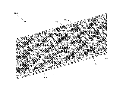
[0050] Another vehicle traction mat 200 is described with reference to FIGS. 6
to 8.
Vehicle traction mat 200 comprises a main mat segment 120, and at least one
other mat
segment 110. The two mat segments are connected to one another via connecting
means
130. Main mat segment 120 and other mat segment 110 are integrally formed, and
connecting means 130 comprises a traverse strip of mat material of reduced
thickness
formed between the main mat segment 120 and the other mat segment 110. This is
preferred to having two separate mat segments connected by mechanical means
which may
break or fail under harsh conditions. The connecting means 130 serve as a
hinge around
LEGAL 28881977.1 - 7 -
1009557-257670 (KB/SA)
CA 2999520 2018-03-28
which mat segments 110 and 120 may be folded to have a reduced area for
storage
purposes.
100511 With reference to FIG. 6, the main mat segment 120 has a longer length
that the
other mat segment 110. In another preferred embodiment (not shown) both mat
segments
have the same shape and dimensions, and connecting means 130 are at the center
portion
between the two mat segments. The advantage of having two mat segments of the
same size
is that when the traction mat 200 is folded, the overall area thereof is
substantially the same
as the area of each of the two segments. Accordingly, this provides for an
optimal overall
size when the main mat segment 120 and the other mat segment 110 are folded
onto one
another in a fully folded position.
[0052] The vehicle traction mat 200 may have a rough tire-facing surface 124
similar to that
of FIG. 2, on both the main segment and the other segment. Alternatively, the
tire-facing
surface of both the main mat 120 segment and the other mat segment 110 may be
provided
with surface pleats 140 only, similar to surface 124 of FIG. 3. In another
embodiment, the
tire-facing surface 124 of the main mat segment 120 and the tire-facing
surface 114 of the
other mat segment 110 may each be provided with knobs 150, knob pleats 160,
and surface
pleats 140.
[0053] To fold vehicle traction mat 200, the other mat segment 110 is folded
around the
connecting means 130 towards the main mat segment 120 with the road-facing
surface 112
coming in proximity with road-facing surface 122. To further optimize the size
of the
folded traction mat 200, the knobs 150 on surface 112 and the knobs 150 on
surface 122 are
positioned to be interleaved with one another. For example, knobs 150 of
surface 122 may
have spaces therebetween suitable for receiving knobs 150 of surface 112 when
mat
segment 110 is folded towards main mat segment 120. Additionally knobs 150 on
surface
112 may be offset by a distance dl from the center line of the connecting
means, while
knobs 150 on surface 122 may be offset by a distance d2 from the center line
of the
connecting means. The two distances dl and d2 are different such that knobs
150 from
surface 122 fit into spaces formed by knobs 150 on surface 112, and vice
versa.
Alternatively, knobs 150 may be staggered on the surfaces 112 and 122 so as to
allow knobs
LEGAL 28881977.1 - 8 -
1009557-257670 (KB/SA)
CA 2999520 2018-03-28
150 on surface 112 to fit in spaces between knobs 150 on surface 122, and vice
versa.
Accordingly, the overall thickness of the fully folded vehicle traction mat
200 is optimized
for easy storage.
[0054] While the surface configuration for both the main mat segment 120 and
the other
mat segment 110 are shown to be similar, other embodiments where the main and
other
segments may be of different configurations are contemplated. For example, the
dimensions
and/or distribution of the knobs 150 on the road-facing surface 122 may be
different than
that of road-facing surface 112. This may be useful, for example, if the
vehicle is stuck in a
large pothole where the bottom surface of the pothole has a surface with
different properties
from the sidewalls of the pothole, then a one mat segment is placed at the
bottom while the
other rests on the sidewalls for optimal traction.
100551 FIGS. 9-20 depict vehicle traction mat 300, in accordance with another
embodiment
of the present disclosure. Vehicle traction mat 300 features a main mat
segment 120 and
two edge mat segments 110. As discussed above, the mat segments may be
integrally
formed and connected via connecting means such as a strip of material of
reduced width
formed between the main mat segment 120 and each of the edge mat segments 110.
For
example, connecting strip 130 may have a thickness of 2mm or another suitable
thickness
that allows traction mat 300 to be folded as shown in FIGS. 17 to FIG. 20,
while at the
same time providing enough strength to resist tearing.
[0056] Vehicle traction mat 300 is shown to have a generally rectangular
shape; however,
other generally planar shapes are also contemplated. For example, main mat
segment 120
may be rectangular, while edge mat segments 110 may be semi-circular, semi-
elliptical,
triangular, or trapezoidal. In some embodiments, the tire-facing surfaces
(124, 114) are
rough. In other embodiments, the tire-facing surfaces (124, 114) have spaced-
apart surface
cleats 140 to provide traction between a rotating vehicle tire (not shown) and
the traction
mat 300. The road-facing surfaces (122, 112) may be provided with knobs 150.
As
discussed earlier, knobs 150 may have the shape of a prism with a triangular,
rectangular,
square, or trapezoidal cross section. Knob cleats 160 provide extra traction
to the mat with
respect to the road surface. In another embodiment, the road-facing surfaces
(122, 112) of
LEGAL 28881977.1 -
9 - 1009557-257670 (KB/SA)
CA 2999520 2018-03-28
the vehicle traction mat 300 may be provided with surface cleats 140 formed in
spaces
between knobs 150. In yet another embodiment, the tire-facing surfaces (124,
114) of
vehicle traction mat 300 may be provided with knobs 150 and cleats 160 for
providing
additional traction between a rotating vehicle tire and the tire-facing
surface. In the
embodiment shown in the accompanying figures, vehicle traction mat 300 has
identical
surfaces, each provided with surface cleats 140, knobs 150, and knob-cleats
160. However,
as previously discussed, the knobs 150 may have different sizes and spacing
for each of the
tire-facing and the road-facing surfaces.
100571 Although the figures depict the knobs 150 and cleats 140 to be evenly
spaced, they
may be scattered around the surface of mats 100, 200, or 300 in an uneven
manner, or in a
staggered pattern. While the knobs are shown to be organized in straight rows
along the
surface of the mats, this is not necessary as many arrangements are
contemplated. The
spacing between knobs 150 is chosen to prevent packed snow or mud from being
stuck
therein thus reducing traction. In a preferred embodiment a 15-25mm spacing
between
knobs 150 is contemplated. The height of knobs 150 may be in the range of 5-
15mm, but
other ranges are also contemplated depending on the expected road surface
condition. The
diameter or side of the knobs may be in the range of 10-30mm but other
dimensions are also
contemplated depending, in part on the shape of the knobs, and the terrain or
road surface
condition.
Different size and spacing ranges are contemplated based on various
considerations such as tire size, vehicle weight, and desired storage size
requirements. The
higher knobs 150 are, for example, the more space the mats 200, and 300 will
take up when
folded. In some embodiments, knobs 150 may be staggered on the surface of
vehicle
traction mat 100 such that knobs 150 from the edge mats 110 would fit into the
spaces
between knobs 150 on the main mat segment 120, when edge mat segments 110 are
folded
towards main mat segment 120. As a result, the effective thickness of the
folded vehicle
traction mat 100 is reduced. Main mat segment 120 and edge mat segments 110
may be
dimensioned for optimal size when vehicle traction mat 300 is folded. For
example, as best
seen in FIG. 12 and FIG. 13, edge mat segments 110 each has a length that is
approximately half the length of main mat segment 120 such that when the
traction mat 300
is folded, its length is substantially equal to that of main mat segment 120.
Edge mat
LEGAL 28881977.1 - 10 -
1009557-257670 (KB/SA)
CA 2999520 2018-03-28
segments 110 need not be identical in size. For example one edge mat segment
may have a
longer length than the length of the other edge mat segment in which case the
lengths of
both edge segments would, added together, be less than or equal to the length
of the main
mat segment 120, and accordingly there would be a space therebetween in folded
mode. In
some embodiments a plurality of mat segments (not shown) are used and may be
fan-folded
for optimal storage dimensions. For example, a vehicle traction mat comprised
of four
square segments arranged longitudinally and connected to one another by
connecting means
in a fan-fold arrangement. The vehicle traction mat can be fan-folded so as to
take up the
space area of a single square segment and four times the thickness of a square
segment. In
another embodiment, the mat may be comprised of three square mat segments
arranged as
an L-shape.
[0058] The above-described embodiments are intended to be examples of the
present
invention and alterations and modifications may be effected thereto, by those
of skill in the
art, without departing from the scope of the invention that is defined solely
by the claims
appended hereto.
LEGAL 28881977.1 - 11 -
1009557-257670 (KB/SA)
CA 2999520 2018-03-28