Note: Descriptions are shown in the official language in which they were submitted.
CA 02999700 2018-03-22
WO 2017/052406 PCT/RU2015/000611
APPARATUS AND METHOD FOR VIDEO MOTION COMPENSATION
TECHNICAL FIELD
The present invention generally relates to the field of video processing and
to
an apparatus for video motion compensation, and specifically relates to a
video coder
and to a video decoder for supporting motion compensation to predict frames in
a
video. The present invention relates further to a method for coding and to a
method for
decoding a video stream using motion compensation. Finally, the present
invention
relates to a computer program having a program code for performing such a
method.
BACKGROUND
In the field of video processing, and in particular in the field of hybrid
video
coding and compression, it is known to use inter and intra prediction as well
as
transform coding. Such hybrid video coding technologies are used in known
video
compression standards like H.261, H.263, MPEG-1, 2, 4, H.264/AVC or
H.265/11EVC.
Fig. 1 shows a video coder according to the state of the art. The video coder
100 comprises an input for receiving input blocks of frames or pictures of a
video
stream and an output for generating an encoded video bit stream. The video
coder 100
is adapted to apply prediction, transformation, quantization, and entropy
coding to the
video stream. The transformation, quantization, and entropy coding are carried
out
respectively by a transform unit 101, a quantization unit 102 and an entropy
encoding
unit 103 so as to generate as an output the encoded video bit stream.
The video stream corresponds to a plurality of frames, wherein each frame is
divided into blocks of a certain size that are either intra or inter coded.
The blocks of
for example the first frame of the video stream are intra coded by means of an
intra
prediction unit 109. An intra frame is coded using only the information within
the
same frame, so that it can be independently decoded and it can provide an
entry point
in the bit stream for random access. Blocks of other frames of the video
stream are
inter coded by means of an inter prediction unit 110: information from coded
frames,
which are called reference frames, are used to reduce the temporal redundancy,
so that
each block of an inter coded frame is predicted from a block of the same size
in a
reference frame. A mode selection unit 108 is adapted to select whether a
block of a
frame is to be processed by the intra prediction unit 109 or the inter
prediction unit
110.
SUBSTITUTE SHEET (RULE 26)
CA 02999700 2018-03-22
WO 2017/052406 PCT/RU2015/000611
2
For performing inter prediction, the coded reference frames are processed by
an
inverse quantization unit 104, an inverse transform unit 105, a loop filtering
unit 106
so as to obtain the reference frames that are then stored in a frame buffer
107.
Particularly, reference blocks of the reference frame can be processed by
these units to
obtain reconstructed reference blocks. The reconstructed reference blocks are
then
recombined into the reference frame.
The inter prediction unit 110 comprises as input a current frame or picture to
be
inter coded and one or several reference frames or pictures from the frame
buffer 107.
Motion estimation and motion compensation are applied by the inter prediction
unit
110. The motion estimation is used to obtain a motion vector and a reference
frame
based on certain cost function. The motion compensation then describes a
current
block of the current frame in terms of the transformation of a reference block
of the
reference frame to the current frame. The inter prediction unit 110 outputs a
prediction
block for the current block, wherein said prediction block minimizes the
difference
between the current block to be coded and its prediction block, i.e. minimizes
the
residual block. The minimization of the residual block is based e.g. on a rate-
distortion
optimization procedure.
The difference between the current block and its prediction, i.e. the residual
block, is then transformed by the transform unit 101. The transform
coefficients are
quantized and entropy coded by the quantization unit 102 and the entropy
encoding
unit 103. The thus generated encoded video bit stream comprises intra coded
blocks
and inter coded blocks.
Such a hybrid video coding comprises motion-compensated prediction
combined with transform coding of the prediction error. For each block, the
estimated
motion vector is also transmitted as signalling data in the encoded video bit
stream.
Today's standards H.264/AVC and H.265/HEVC are based on 1/4 pel displacement
resolution for the motion vector. In order to estimate and compensate the
fractional-pel
displacements, the reference frame has to be interpolated on the fractional-
pel
positions. To obtain such an interpolated frame on the fractional-pel
positions, an
interpolation filter is used in the inter prediction unit 110.
The quality of the interpolated frame strongly depends on the properties of
the
used interpolation filter. Short-tap filters, e.g. bilinear filters, may
suppress high
SUBSTITUTE SHEET (RULE 26)
CA 02999700 2018-03-22
WO 2017/052406 PCT/RU2015/000611
3
frequencies and render the interpolated frame blurred. Other filters like long-
tap filters
may preserve high frequencies but generate some ringing artifacts in the
neighbourhood of sharp edges. Another problem is that the motion compensation
makes use of a previously encoded and reconstructed frame as a reference
frame: the
reference frame may contain artifacts caused by quantization of transform
coefficient,
which is referred to as Gibbs effect. Because of these artifacts, the edges as
well as the
area around the edges may also be distorted.
Is it known in the prior art that the quality of the edges may be increased by
applying a sharpening or de-blurring post-filter to the decoded frame. The
problem of
such post-filtering design is that the sharpening filter is not included in to
encoding
process. Thus the effect of the sharpening filter cannot be taken into account
during the
rate-distortion optimization procedure. This may lead to reduced objective
quality
metrics, like the peak signal-to-noise-ratio (PSNR).
To increase the objective quality, it is also known in the prior art to
include a
sharpening filter into the loop filtering unit 106. Accordingly, the
sharpening filter is
applied to the reconstructed reference frame and may improve motion-
compensated
prediction by removing compression artifacts in the reference frame. However
such a
loop filtering technique cannot remove artifacts caused by the motion
interpolation
filter.
SUMMARY
Having recognized the above-mentioned disadvantages and problems, the
present invention aims to improve the state of the art. In particular, the
object of the
present invention is to provide a video coder, a coding method, a video
decoder, and a
decoding method for an improved coding and decoding of a video stream of
subsequent frames.
The present invention particularly intends to improve the quality of the inter
predictive coding. Particularly, the invention intends to remove artifacts
caused by the
motion estimation and motion compensation. Specifically it is the aim of the
present
invention to reduce negative effects of the motion interpolation filter, i.e.
to reduce
negative effects of the interpolation of the reference frame on fractional-pel
positions
as well as improving quality of prediction by reducing quantization artefacts
of
reference frame.
SUBSTITUTE SHEET (RULE 26)
CA 02999700 2018-03-22
WO 2017/052406 PCT/RU2015/000611
4
The above-mentioned object of the present invention is achieved by the
solution provided in the enclosed independent claims. Advantageous
implementations
of the present invention are further defined in the respective dependent
claims.
A first aspect of the present invention provides a video coder for predictive
coding a video stream of subsequent frames according to motion compensation
into an
encoded video bit stream. The video coder comprises a frame buffer adapted to
store at
least one reference frame of the video stream, said reference frame being
different
from a current frame of the video stream. The video coder comprises an inter
prediction unit adapted to generate a prediction block of a current block of
the current
frame from a reference block of the reference frame. The video coder comprises
an
adaptive sharpening filter configured to adaptively filter the prediction
block.
Thereby, applying the adaptive sharpening filter to the prediction block
improves the quality of the inter predictive coding in that it removes or at
least reduces
the ringing artifacts caused by the interpolation of the reference frame/block
on
fractional-pel positions, i.e. caused by the motion interpolation filter,
while
advantageously keeping quality interpolated edges. It also removes or at least
reduces
the ringing artifacts, also referred to as Gibbs effect, caused by the
quantization of
transform coefficients in the reference block. It further on reduces the
blurring of edges
caused by the quantization and motion interpolation, and also reduces the
blurring of
edges caused by motion blur. Additionally, the present invention increases the
subjective quality of edges in the reconstructed frame/block.
Thereby, the placement of the sharpening filter according to the invention
after
the motion interpolation filter, i.e. after the inter prediction unit, causes
the sharpening
filter to carry out the task of the in-loop reference filters, i.e. of the
loop filtering unit,
while at the same time the artifacts caused by motion interpolation filtering
can be
removed or at least reduced. Also, the use of an adaptive sharpening filter
makes it
possible to adapt to local features of the video content and particularly of
the
prediction block, so that the coding of even small blocks only requires a
reduced
signalling overhead for the transmission to a decoder.
In an implementation form of the video coder according to the first aspect,
the
video coder comprises a control unit. The adaptive sharpening filter is
configured to be
controlled by at least one adaptive parameter. The control unit is configured
to
SUBSTITUTE SHEET (RULE 26)
CA 02999700 2018-03-22
WO 2017/052406 PCT/RU2015/000611
determine a parameter value of the adaptive parameter and supply the
determined
parameter value to the adaptive sharpening filter.
Thereby, the prediction block is filtered by a sharpening filter that can be
adapted to the specific content of the video. The adaptation can take account
of local
5 features of the video content and the required signalling overhead can be
limited due to
using of parametric representation of adaptive sharpening filter with only one
coefficient for adaptation and transmission. Particularly, the size of the
blocks used for
predictive coding can be reduced without at the same time increasing the
signalling
overhead.
In a further implementation form of the video coder according to the first
aspect, the control unit is configured to supply different parameter values
for the
adaptive parameter and to select one of the different parameter values based
on a
minimization of a residual block, said residual block being the difference
between the
current block and the prediction block, or based on a cost criterion such as,
for
example, a rate distortion optimization.
Thereby, the motion compensation can be further improved. The residual
blocks obtained for different values of the at least one adaptive parameter
can be
compared. By selecting the prediction block that minimizes the residual block
or that
minimizes a cost criterion, the motion compensation can be improved. The
parameter
value corresponding to the selected prediction block is then selected from
among the
different parameter values so as to improve the motion compensation.
In a further implementation form of the video coder according to the first
aspect, the sharpening filter is a non-linear filter.
Thereby, that usage of such a non-linear sharpening filter is preferable for
motion prediction enhancement. Traditional edge enhancement techniques based
on
linear sharpening or de-blurring filters, like unsharp masking techniques, may
increase
subjective quality but cannot suppress the ringing artifacts caused by motion
interpolation filtering. It has also been discovered that in most cases, such
linear
sharpening even may increase ringing and reduce the objective performance
characteristics. On the other, non-linear filters can provide better results
for ringing
elimination and are thus advantageous. Also, the use of a non-linear design
for the
sharpening filter, i.e. for the adaptive sharpening filter, can advantageously
reduce the
SUBSTITUTE SHEET (RULE 26)
CA 02999700 2018-03-22
WO 2017/052406 PCT/RU2015/000611
6
number of adaptive parameters and thus the signalling overhead.
In a further implementation form of the video coder according to the first
aspect, the sharpening filter comprises an edge map calculation unit adapted
to
generate an edge map of a source block, said source block being the reference
block or
the prediction block. The sharpening filter comprises a blurring filter
adapted to blur
the edge map of the source block. The sharpening filter comprises a high-pass
filter
adapted to generate, by high-pass filtering the blurred edge map, a derivative
vector for
each position of the source block. The sharpening filter comprises a scaling
unit
adapted to generate a displacement vector by scaling the derivative vector
with a
sharpening strength coefficient. The sharpening filter comprises a warping
unit adapted
to warp the prediction block based on the displacement vector. The adaptive
parameter
includes the sharpening strength coefficient.
Thereby, this structure of the sharpening filter defines a non-linear
sharpening
filter that advantageously can provide better results in terms of elimination
of ringing
artifacts. Also, the use of the sharpening strength coefficient as adaptive
parameter
implies that only one adaptive parameter is required, which further reduces
the
signalling overhead.
In a further implementation form of the video coder according to the first
aspect, the sharpening filter is always enabled.
In a further implementation form of the video coder according to the first
aspect, the video coder comprises a control unit configured to control at
least one of a
selective bypass of the adaptive sharpening filter and a selective application
of the
adaptive sharpening filter.
Thereby, a decision can be taken by the control unit to apply or bypass the
sharpening filter. The decision can then be adapted to each particular case,
for example
to the particular video stream to be encoded. Also, the sharpening filter can
be
bypassed to save computational resources in the video coder. On the other
hand, the
sharpening filter can be applied if the priority shall be given to the
improvement of the
interpolation quality and the reduction of artifacts.
In a further implementation form of the video coder according to the first
aspect, the control unit is adapted to control the at least one of the
selective bypass and
the selective application depending on a cost function to minimize a residual
block.
SUBSTITUTE SHEET (RULE 26)
CA 02999700 2018-03-22
WO 2017/052406 PCT/RU2015/000611
7
Said residual block may be the difference between the current block and the
prediction
block. The cost function may be, for example, based on the rate distortion
optimization.
Thereby, the possibility of bypassing or applying the sharpening filter can be
further used to improve the motion compensation. The two residual blocks
derived
respectively from the prediction block outputted by the inter prediction unit
and from
the prediction block outputted by the sharpening filter can be compared in
terms of the
cost function. By choosing the prediction block that minimized the residual
block and
by correspondingly applying or bypassing the sharpening filter, the quantity
of data
and for example the quantity of transform coefficients to be encoded can be
reduced.
In a further implementation form of the video coder according to the first
aspect, the video coder comprises an encoding unit adapted to generate the
encoded
video bit stream. The control unit is adapted to transmit to the encoding unit
sharpening filter information reflecting the at least one of the selective
bypass and the
selective application of the sharpening filter. The encoding unit is adapted
to add the
sharpening filter information in the encoded video bit stream.
Thereby, when decoding the encoded video bit stream, it is possible to obtain
this sharpening filter information and to accordingly apply or bypass the
sharpening
filter on the decoder side, so as to guarantee a correct decoding.
In a further implementation form of the video coder according to the first
aspect, the adaptive parameter information or the sharpening filter
information is
added at a block level for each prediction block, for an arbitrary or regular
region of
the frame, at a frame level, at a GOP (group of pictures) level, at a PPS
(picture
parameter set) level or at an SPS (sequence parameter set) level.
Thereby, it is possible to set the sharpening filter information to a desired
granularity so that the signalling can be optimized.
In a further implementation form of the video coder according to the first
aspect, the adaptive sharpening filter comprises a single adaptive parameter.
Thereby, the signalling overhead that is required for the adaptation and that
is
transmitted to a decoded can be further reduced.
A second aspect of the present invention provides a method for predictive
coding a video stream of subsequent frames according to motion compensation
into an
SUBSTITUTE SHEET (RULE 26)
CA 02999700 2018-03-22
WO 2017/052406 PCT/RU2015/000611
8
encoded video bit stream. The method comprises storing at least one reference
frame
of the video stream, said reference frame being different from a current frame
of the
video stream. The method comprises generating a prediction block of a current
block
of the current frame from a reference block of the reference frame. The method
comprises adaptively filtering the prediction block.
Further features or implementations of the method according to the second
aspect of the invention can perform the functionality of the video coder
according to
the first aspect of the invention and its different implementation forms.
A third aspect of the present invention provides a video decoder for decoding
an encoded video bit stream obtained by predictive coding a video stream of
subsequent frames according to motion compensation. The video decoder
comprises a
frame buffer adapted to store at least one reference frame obtained from the
encoded
video bit stream, said reference frame being different from a current frame of
the
encoded video bit stream. The video decoder comprises an inter prediction unit
adapted to generate a prediction block of a current block of the current frame
from a
reference block of the reference frame. The video decoder comprises an
adaptive
sharpening filter adapted to adaptively filter the prediction block.
Thereby, the advantages obtained with respect to the video coder according to
the first aspect are also given with respect to the video decoder according to
the third
aspect.
In an implementation form of the video decoder according to the third aspect,
the video decoder comprises a control unit. The adaptive sharpening filter is
configured to be controlled by at least one adaptive parameter. The control
unit is
configured to determine a parameter value of the adaptive parameter and to
supply the
determined parameter value to the adaptive sharpening filter.
Thereby, the sharpening filter can be advantageously adapted by means of the
at least one adaptive parameter.
In an implementation form of the video decoder according to the third aspect,
the control unit is configured to determine the parameter value of the
adaptive
parameter depending on adaptive parameter information obtained from the
encoded
video bit stream.
Thereby, the adaptive parameter can be obtained from the encoded video bit
SUBSTITUTE SHEET (RULE 26)
CA 02999700 2018-03-22
WO 2017/052406 PCT/RU2015/000611
9
stream generated by video coder. It can thus be ensured that both the video
coder and
the video decoder carry out the same adaptation of the sharpening filter and
that the
video obtained by the video decoder corresponds to the video encoded by the
video
coder.
In an implementation form of the video decoder according to the third aspect,
the video decoder comprises a control unit adapted to control at least one of
a selective
bypass of the adaptive sharpening filter and a selective application of the
adaptive
sharpening filter.
Thereby, the decision to use or not the sharpening filer unit can be adapted
to
each particular case. Also, the sharpening filter can be bypassed to save
computational
resources in the video coder and the video decoder. On the other hand, the
sharpening
filter can be applied if the priority shall be given to the improvement of the
interpolation quality and the reduction of artifacts.
In an implementation form of the video decoder according to the third aspect,
the control unit is adapted to control the at least one of the selective
bypass and the
selective application based on sharpening filter information obtained from the
encoded
video bit stream.
Thereby, the video decoder can be adapted to the video coder that may
advantageously add in the encoded video bit stream such sharpening filter
information
that reflects the switching on or off of the sharpening filter on the video
coder side.
Further features or implementations of the video coder according to the first
aspect of the invention, particularly regarding the sharpening filter and its
structure, are
also applicable to the video decoder according to the third aspect of the
invention.
A fourth aspect of the present invention provides a method for decoding an
encoded video bit stream obtained by predictive coding a video stream of
subsequent
frames according to motion compensation. The method comprises storing at least
one
reference frame obtained from the encoded video bit stream, said reference
frame
being different from a current frame of the encoded video bit stream. The
method
comprises generating a prediction block of a current block of the current
frame from a
reference block of the reference frame. The method comprises adaptively
filtering the
prediction block.
Further features or implementations of the method according to the fourth
SUBSTITUTE SHEET (RULE 26)
CA 02999700 2018-03-22
WO 2017/052406 PCT/RU2015/000611
aspect of the invention can perform the functionality of the video decoder
according to
the third aspect of the invention and its different implementation forms.
A fifth aspect of the present invention provides a computer program having a
program code for performing such a coding and/or decoding method when the
5 computer program runs on a computing device.
The invention proposes a motion compensation improvement by applying an
adaptive sharpening filter to the motion prediction signal i.e. to the
prediction blocks.
It is proposed to improve the motion compensation by reducing ringing
artifacts and
increasing the sharpness of edges in motion prediction blocks. It is proposed
to apply
10 the sharpening filter as a prediction filter placed both in the encoder
and the decoder
for motion compensation enhancement. A non-linear sharpening prediction filter
can
be used for motion compensation improvement.
It has to be noted that all devices, elements, units and means described in
the
present application could be implemented in the software or hardware elements
or any
kind of combination thereof. All steps which are performed by the various
entities
described in the present application as well as the functionalities described
to be
performed by the various entities are intended to mean that the respective
entity is
adapted to or configured to perform the respective steps and functionalities.
Even if, in
the following description of specific embodiments, a specific functionality or
step to
be full formed by eternal entities not reflected in the description of a
specific detailed
element of that entity which performs that specific step or functionality, it
should be
clear for a skilled person that these methods and functionalities can be
implemented in
respective software or hardware elements, or any kind of combination thereof.
BRIEF DESCRIPTION OF DRAWINGS
The above aspects and implementation forms of the present invention will be
explained in the following description of specific embodiments in relation to
the
enclosed drawings, in which
Fig. 1 shows a video coder according to the state of the art,
Fig. 2 shows a video coder according to an embodiment of the present
invention,
Fig. 3 shows a video decoder according to an embodiment of the present
invention,
SUBSTITUTE SHEET (RULE 26)
CA 02999700 2018-03-22
WO 2017/052406 PCT/RU2015/000611
11
Fig. 4 shows an embodiment of a sharpening filter according to the present
invention,
Fig. 5 shows a video coding method according to an embodiment of the present
invention,
Fig. 6 shows a video decoding method according to an embodiment of the
present invention,
Fig. 7 shows a sharpening adaptation according to an embodiment of the
present invention, and
Fig. 8 shows possible embodiments for the sharpening adaptation shown in Fig.
7.
DETAILED DESCRIPTION OF EMBODIMENTS
Fig. 2 shows a video coder according to an embodiment of the present
invention, and particularly a video coder 200 for predictive coding a video
stream of
subsequent frames according to motion compensation into an encoded video bit
stream.
The video coder 200 comprises particularly a frame buffer 207, an inter
prediction unit 210, and a sharpening filter 211.
The frame buffer 207 is adapted to store at least one reference frame or
picture
of the video stream. Said reference frame is different from a current frame of
the video
stream. Particularly and in the context of the invention, the current frame is
a frame of
the video stream that is currently encoded, while the reference frame is a
frame of the
video stream that has already been encoded. In the followings, any reference
to the
feature "frame" may be replaced by a reference to the feature "picture".
The inter prediction unit 210 is adapted to generate a prediction block of a
current block of the current frame from a reference block of the reference
frame. The
reference frame is preferably the reference frame stored in the frame buffer
207, while
the current block preferably corresponds to the input of the video coder 200
referred to
as video block in Fig. 2. Particularly, the current frame is encoded using an
inter
coding technique, i.e. the current frame is predicted from the at least one
reference
frame that is distinct from the current frame. The reference frame can be a
previous
frame, i.e. a frame that is located prior to the current frame within the
video stream of
subsequent frames. Alternatively if forward prediction is used, the reference
frame can
SUBSTITUTE SHEET (RULE 26)
CA 02999700 2018-03-22
WO 2017/052406 PCT/RU2015/000611
12
be a future frame, i.e. a frame that is located after the current frame. In
case of a
plurality of reference frames, at least one can be such a previous frame and
at least one
of them can be such a future frame. A reference frame can be intra coded, i.e.
can be
coded without using any further frame and without any dependence on other
frames, so
that it can be independently decoded and it can serve as entry point for
random video
access.
Particularly, the inter prediction unit 210 is adapted to perform motion
estimation by generating a motion vector and estimating motion between the
reference
block of the reference frame and the current block of the current frame. Said
motion
estimation is performed during encoding to find the motion vector pointing to
the best
reference block in the reference frame based on certain cost function being,
for
example, the rate-distortion optimization. Beside the motion estimation, the
inter
prediction unit 210 is further adapted to perform motion compensation by
generating
the prediction block for the current block on the basis of the motion vector
and the
reference block.
Particularly, the motion prediction comprises a motion estimation unit and a
motion compensation unit. The motion vector is generated by using a motion
estimation unit. The reference block and the current block are preferably a
respective
area or sub-area of the reference frame and the current frame. Such a block
may have a
regular shape, like e.g. a rectangular shape, or an irregular shape.
Alternatively, the
blocks can have the same size as the frames. Both the current block and the
reference
block have the same size. The size of the blocks can be defined by means of
block
mode information transmitted as side information or signalling data to the
decoder. A
block can correspond to a coding unit that is a basic coding structure of the
video
sequence of a pre-defined size, containing a part of a frame, e.g. 64x64
pixels.
The prediction block is generated for the current block in view of the
reference
block. Particularly, a plurality of prediction blocks can be generated for a
plurality of
current blocks of the current frame in view of a plurality of reference
blocks. These
reference blocks can be part of a single reference frame or can be selected
from
different reference frames. Several prediction blocks can be generated for the
current
frame, and the prediction blocks generated for the current frame can be
combined to
obtain a prediction frame of the current frame.
SUBSTITUTE SHEET (RULE 26)
CA 02999700 2018-03-22
WO 2017/052406 PCT/RU2015/000611
13
The sharpening filter 211 is an adaptive sharpening filter that is configured
to
adaptively filter the prediction block. The sharpening filter 211 is thus
applied to the
prediction block generated by the inter prediction unit 210. The sharpening
filter 211
proposed by the invention is added after the inter prediction unit 210 so as
to enhance
the prediction block obtained by the inter prediction, i.e. obtained by the
motion
prediction comprising the motion estimation and the motion compensation. The
sharpening filter 211 is thus adapted to generate a sharpened prediction
block.
The video coder 200 advantageously comprises a control unit 212, and the
adaptive sharpening filter 211 utilizes (i.e., is configured to be controlled
by) at least
one adaptive parameter. The control unit 212 is configured to determine a
parameter
value of the adaptive parameter and supply the determined parameter value to
the
adaptive sharpening filter 211.
Preferably, the adaptive sharpening filter 211 utilizes only one adaptive
parameter, values of which being set by the control unit 212.
The control unit 212 may be configured to determine the parameter value by
supplying different parameter values for the adaptive parameter and selecting
one of
the different parameter values based on a minimization of a residual block,
said
residual block being the difference between the current block and the
prediction block,
or based on a cost criterion that is for example a rate distortion
optimization.
The video coder 200 advantageously comprises an encoding unit 203
configured to generate the encoded video bit stream. The control unit 212 is
configured
to transmit to the encoding unit 203 adaptive parameter information about the
determined parameter value. The encoding unit 203 is configured to add the
adaptive
parameter information in the encoded video bit stream. This means that, once
the
control unit 212 has set the adaptive parameter to a given value or the
adaptive
parameters to respective given values, said control unit 212 transmits the
given
value(s) to the encoding unit 203 that adds the given value(s) to the encoded
video bit
stream as signalling data.
The video coder 200 of Fig. 2 comprises further units similar to the video
coder
100 of Fig. 1 for particularly supporting hybrid video coding. For example,
the video
coder 200 comprises similar units that are a transform unit 201, a
quantization unit 202
and the entropy encoder or entropy encoding unit 203 for, as already known in
the art,
SUBSTITUTE SHEET (RULE 26)
CA 02999700 2018-03-22
WO 2017/052406 PCT/RU2015/000611
14
generating transform coefficients via a transformation into the frequency
domain,
quantizing the coefficients and entropy coding the quantized coefficients for
example
together with signalling data. The input of the transform unit 201 is a
residual block
defined as the difference between the current block of the current frame,
referred to as
video block in Fig. 2, and the prediction block outputted by the inter
prediction unit
210, the sharpening filter 211 or an intra prediction unit 209. The entropy
encoding
unit 203 is adapted to generate as an output the encoded video bit stream.
The video coder 200 comprises further similar units that are an inverse
quantization unit 204, an inverse transform unit 205 and a loop filtering unit
206. The
quantized transform coefficients generated by the quantization unit 202 are
inverse
quantized and inverse transformed by respectively the inverse quantization
unit 204
and inverse transform unit 205 to obtain a reconstructed residual block
corresponding
to the residual block fed to the transform unit 201. The reconstructed
residual block is
then added to the prediction block previously used for generating the residual
block, so
as to obtain a reconstructed current block corresponding to the current block,
this
reconstructed current block being referred to as reconstructed video block in
Fig. 2.
The reconstructed current block may be processed by the loop filtering unit
206 to
smooth out artifacts that are introduced by the block-wise processing and
quantization.
The current frame, which comprises at least one current block or
advantageously a
plurality of current blocks, can then be reconstructed from the reconstructed
current
block(s). This reconstructed current frame can be stored in the frame buffer
207 for
serving as reference frame for inter prediction of another frame of the video
stream.
A mode selection unit 208 is provided in the video coder 200 for, similarly to
Fig. 1, selecting whether an input block of the video coder 200 is to be
processed by
the intra prediction unit 209 or the inter prediction unit 210. The mode
selection unit
208 correspondingly chooses if a block of a frame is to be intra coded using
only
information from this frame, or is to be inter coded using additional
information from
other frames i.e. from at least one reference frame stored in the frame buffer
207.
The intra prediction unit 209 is responsible for the intra prediction and
generates a prediction block based on intra prediction. As mentioned above,
the inter
prediction unit 210 is responsible for the inter prediction and generates a
prediction
block that is predicted from a block of the same size in a reference frame, so
as to
SUBSTITUTE SHEET (RULE 26)
CA 02999700 2018-03-22
WO 2017/052406 PCT/RU2015/000611
reduce the temporal redundancy.
Particularly, the sharpening filter 211 can be always enabled. This means that
the prediction block generated by the inter prediction unit 210 is always fed
to the
sharpening filter 211, and that the residual block is always obtained by the
difference
5 of the
current block and the sharpened prediction block that is outputted by the
sharpening filter 211.
Alternatively, the sharpening filter 211 can be selectively bypassed and/or
selectively applied. In case the sharpening filter 211 is applied, the
sharpening filter
211 generates a sharpened prediction block and the residual block is obtained
by the
10
difference of the current block and the sharpened prediction block that is
outputted by
the sharpening filter 211. In case the sharpening filter 211 is bypassed, the
residual
block is obtained by the difference of the current block and the prediction
block that is
outputted by the inter prediction unit 210.
The selective bypass and/or application of the sharpening filter 211 may be
15
controlled by the control unit 212. The control unit may be, for example,
adapted to
control the application and/or bypassing of the sharpening filter 211
depending on a
cost function to minimize the residual block. The cost function may be, for
example,
based on the rate distortion optimization. The cost function may be
particularly applied
to the residual block obtained from the prediction block that is outputted by
the
sharpening filter 211, and to the residual blocks obtained from the prediction
block that
is outputted by the inter prediction unit 210. Depending on the result of the
cost
function, the sharpening filter 211 may be either applied or bypassed.
The decision of the control unit 212 to bypass or apply the sharpening filter
211
can be transmitted as signalling data within the encoded video bit stream
generated by
the encoding unit or entropy encoding unit 203. The control unit 212 transmits
sharpening filter information to the encoding unit 203, said sharpening filter
information reflecting at least one of the selective bypass and selective
application of
the sharpening filter 211. The encoding unit 203 then adds the sharpening
filter
information as signalling data in the encoded video bit stream.
The sharpening filter information can be in the form of a sharpening filter
flag
that can take two values, for example 0 and 1. One of these two values, for
example 1,
defines that the sharpening filter is applied, while the other value defines
that the
SUBSTITUTE SHEET (RULE 26)
CA 02999700 2018-03-22
WO 2017/052406 PCT/RU2015/000611
16
sharpening filter is bypassed. Alternatively, the absence of sharpening filter
information can be interpreted as reflecting the bypassed state of the
sharpening filter,
while the presence of sharpening filter information can reflect the
application state.
The granularity of the adaptive parameter information and/or sharpening filter
information can vary. The sharpening filter information can for example added
at a
block level for each prediction block, for an arbitrary or regular region of
the frame, at
a frame level, at a GOP (group of pictures) level, at a PPS (picture parameter
set) level
or at an SPS (sequence parameter set) level. If the sharpening filter
information is
added at a block level for each prediction block, the encoding unit 203 can
add the
sharpening filter information for each prediction block generated by the inter
prediction unit 210. The encoding unit 203 then adds to the encoded video bit
stream,
for each prediction block, the corresponding quantized residual transform
coefficients
and the corresponding sharpening filter information.
Fig. 3 shows a video decoder according to an embodiment of the present
invention, and particularly a video decoder 300 for decoding an encoded video
bit
stream obtained by predictive coding a video stream of subsequent frames
according to
motion compensation.
The video decoder 300 comprises particularly a frame buffer 307, an inter
prediction unit 310, and an adaptive sharpening filter 311. The frame buffer
307 is
adapted to store at least one reference frame obtained from the encoded video
bit
stream, said reference frame being different from a current frame of the
encoded video
bit stream. The inter prediction unit 310 is adapted to generate a prediction
block of a
current block of the current frame from a reference block of the reference
frame. The
adaptive sharpening filter 311 is configured to adaptively filter the
prediction block.
Advantageously, the video decoder 300 comprises a control unit 312, and the
adaptive sharpening filter 311 utilizes at least one adaptive parameter. The
control unit
312 is configured to determine a parameter value of the adaptive parameter and
to
supply the determined parameter value to the adaptive sharpening filter 311.
The control unit 312 may be particularly configured to determine the parameter
value of the adaptive parameter depending on adaptive parameter information
obtained
from the encoded video bit stream.
The decoder 300 is adapted to decode the encoded video bit stream generated
SUBSTITUTE SHEET (RULE 26)
CA 02999700 2018-03-22
WO 2017/052406 PCT/RU2015/000611
17
by the video coder 200, and both the decoder 300 and the coder 200 generate
identical
predictions. The features of the frame buffer 307, the inter prediction unit
310, and the
sharpening filter 311 are similar to the features of the frame buffer 207, the
inter
prediction unit 210, and the sharpening filter 211 of Fig. 2.
For ensuring identical predictions on the coder side and on the decoder side,
the
adaptive parameter(s) of the sharpening filter of the coder 200 may be passed
to the
decoder 300 as signalling data. As alternative solution, the adaptive
parameter(s) may
be derived on the decoder side without sending corresponding signalling data.
Particularly, the adaptive parameter(s) may be derived from a surrounding area
or from
the reference frame. For example, the parameter(s) may be derived from a
surrounding
block in the current frame, e.g. can be the same as adaptive parameter(s) of a
surrounding block with respect to the current block.
Particularly, the video decoder 300 may comprise further units that are also
present in the video coder 200 like e.g. an inverse quantization unit 304, an
inverse
transform unit 305, a loop filtering unit 306 and an intra prediction unit
309, which
respectively correspond to the inverse quantization unit 204, the inverse
transform unit
205, the loop filtering unit 206 and the intra prediction unit 209 of the
video coder 200.
An entropy decoding unit 303 is adapted to decode the received encoded video
bit
stream and to correspondingly obtain quantized residual transform coefficients
and, if
present, sharpening filter information. The quantized residual transform
coefficients
are fed to the inverse quantization unit 304 and an inverse transform unit 305
to
generate a residual block. The residual block is added to a prediction block
and the
addition is fed to the loop filtering unit 306 to obtain the decoded video.
Frames of the
decoded video can be stored in the frame buffer 307 and serve as a reference
frame for
inter prediction.
Particularly, the sharpening filter 311 may be always enabled. This means that
the prediction unit filtered by the sharpening filter is used to obtain the
decoded video.
Alternatively, the sharpening filter 311 may be selectively bypassed or
applied
by, for example, the control unit 312. The sharpening filter information
obtained by the
decoding unit 303 from the encoded video bit stream may be fed to the control
unit
312 that controls the bypassing and/or application of the sharpening filter
311
depending on the sharpening filter information.
SUBSTITUTE SHEET (RULE 26)
CA 02999700 2018-03-22
WO 2017/052406 PCT/RU2015/000611
18
The sharpening filter information reflects the bypassing or application of the
sharpening filter 311 and preferably corresponds to the sharpening filter
information
added by the video coder 200 to the encoded video bit stream. The different
aspects
regarding for example the form and the granularity of the sharpening filter
information
discussed with respect to the video coder 200 also apply with respect to the
video
decoder 300.
Fig. 4 shows an embodiment of an adaptive sharpening filter 400 according to
the present invention, and particularly an embodiment of the adaptive
sharpening filter
211 of the video coder 200. The adaptive sharpening filter 311 of the video
decoder
300 may be slightly different from the adaptive sharpening filter 211 shown in
Fig. 4,
the difference being discussed below.
The sharpening filter 400 is preferably a non-linear filter. The usage of a
non-
linear sharpening filter, instead of a linear filter, is preferable for
removing artifacts
caused by the motion interpolation filter and the quantization of the
reference block or
frame. The choice of a non-linear filter can reduce the number of adaptive
parameters
of the sharpening filter 400. In particular, the non-linear filter can utilize
only one
adaptive parameter, so that the signalling overhead of the encoded video bit
stream is
reduced. While the present invention also covers the use of more than one
adaptive
parameter to control sharpening filter 400, a sharpening filter utilizing only
one
adaptive parameter is a particularly advantageous embodiment.
Particularly, the sharpening filter 400 comprises an edge map calculation unit
401, 402, a blurring filter 404, a high-pass filter 405, a scaling unit 406
and a warping
unit 407.
The edge map calculation unit 401, 402 is adapted to generate an edge map of a
source block, said source block being the reference block or the prediction
block. The
blurring filter 404 is adapted to blur the edge map of the source block. The
high-pass
filter 405 is adapted to generate, by high-pass filtering the blurred edge
map, a
derivative vector (d2x, d2y) for each position of the source block. The
scaling unit 406
is adapted to generate a displacement vector (wx, wy) by scaling the
derivative vector
(d2x, d2y) with a sharpening strength coefficient k. The warping unit 407 is
adapted to
warp the prediction block based on the displacement vector (wx, wy).
Thereby, the adaptive parameter controlling the sharpening filter 400 is the
SUBSTITUTE SHEET (RULE 26)
CA 02999700 2018-03-22
WO 2017/052406 PCT/RU2015/000611
19
sharpening strength coefficient k. The sharpening filter 400 shown in Fig. 4
is an
embodiment of the present invention with only one adaptive parameter.
The edge map calculation unit 401, 402 can comprise a gradient vector unit 401
adapted to generate a gradient vector (dx, dy) for each position of the source
block, and
a gradient vector length unit 402 adapted to calculate the length of the
gradient vector
(dx, dy) of each position so as to generate the edge map of the source block.
Thereby,
this structure allows for the generation of an edge map that can be further
processed by
the blurring filter, the high-pass filter and the scaling unit to generate the
warping
displacement vector.
The gradient vector can be obtained by taking the first derivative separately
for
dx and dy, i.e. separately for both a horizontal and a vertical direction of
the source
block referred to as source block in Fig. 4, by applying a corresponding
Prewitt filter
in accordance with the following equations:
1 0 ¨1
dx = 1 0 -1 * img
1 0 -1
1 1 1
dy = 0 0 0 * img
¨1 ¨1 ¨1
-
The edge map can be obtained by the gradient vector length unit 402 by
calculating the gradient vector length in accordance with the following
equation:
abs = Ni dx2 + dy2
Advantageously, the sharpening filter 400 comprises a clipping unit 403
adapted to clip the edge map of the source block, said clipping unit 403 being
located
between the edge map calculation unit 401, 402 and the blurring filter 404.
Thereby,
the clipping of the edge map with thresholds is advantageous in that it
'prevents the
processing of extremely high and low values of warping vectors.
The step of blurring of the clipped edge map can be obtained by a blurring
filter
404 in form of a Gaussian filter that can be defined as follows:
SUBSTITUTE SHEET (RULE 26)
CA 02999700 2018-03-22
WO 2017/052406 PCT/RU2015/000611
1 4 7 4 1
4 16 26 16 4
G= 7 26 41 26 7
4 16 26 16 4
.1 4 7 4 1,
The high-pass filter is used to obtain, separately for d2x and d2y, the second
derivative, for example according to the followings:
d2x = [1 0 ¨1]
d2y- 01
- -11
5
The displacement vector (w-x,wy) is obtained by scaling the second derivative
vector (d2x, d2y) with the coefficient k, wherein the coefficient k can be
considered as
sharpening strength, according to the following equations:
wx=k*d2x
10 wy=k*d2y
The warping unit 407 includes an interpolation filter that is e.g. a bi-linear
interpolation filter to obtain sample values at fractional-pel positions. The
warping unit
407 uses the displacement vector generated by the scaling unit 406. Thereby,
the
overall quality of the video coder is= improved while at the same time
providing an
15 interpolation of the reference frame/block on desired fractional-pel
positions.
A subtracting unit 408 is adapted to build the difference between the
sharpened
prediction block generated by the warping unit 407 and the current block, said
current
block corresponding to the block to be encoded. The subtracting unit 408 in
fact
generates the residual block. The adaptive sharpening filter 400, or the
control unit 211
20 controlling the adaptive sharpening filter 400, is adapted to find the
optimum
sharpening strength k for example by minimizing the residual block or by a
cost
criterion based e.g. on the rate-distortion.
The difference between the adaptive sharpening filters of the video coder 200
and of the video decoder 300 preferably consists in this subtracting unit 408
and in this
minimization of the residual block. In the video decoder 300, the adaptive
parameter,
i.e. the coefficient k, is not set by means of the subtracting unit 408 and
the
minimization of the residual block. Instead, the adaptive parameter is set= in
the video
SUBSTITUTE SHEET (RULE 26)
CA 02999700 2018-03-22
WO 2017/052406 PCT/RU2015/000611
21
decoder 300 preferably depending on signalling data reflecting the value of
the
coefficient k, said signalling data being part of the encoded video bit stream
and being
set by the video coder 200.
The sharpening filter 400 comprises a warping based on a displacement vector
calculated from the source block, which source block is referred to in Fig. 4
as motion
prediction block.
According to an embodiment not shown in Fig. 4, the source block is the
reference block of the reference frame stored in the frame buffer 207, 307,
such that
the displacement vector (wx, wy) is derived from the reference block. Thereby,
the
reference block is used as source block for obtaining the displacement
vectors, which
are also called sharpening displacement vectors or warping displacement
vectors. The
warping is then applied to the prediction block using the obtained
displacement vector.
This embodiment is advantageous in that is saves computational resources on
the
encoder side.
According to the alternative embodiment of Fig. 4, the source block is the
prediction block generated by the inter prediction unit 210, 310, such that
the
displacement vector (wx, wy) is derived from the prediction block.
Thereby, choosing the prediction block as source block allows for the
calculation of suitable displacement vectors for carrying out the warping of
the
prediction block. Also, the sharpening filter then only requires one input for
the
prediction block and a second input for the reference block is not needed.
Fig. 5 shows a video coding method according to an embodiment of the present
invention, and particularly a method 500 for predictive coding a video stream
of
subsequent frames according to motion compensation into an encoded video bit
stream.
The method 500 comprises a step 501 of storing at least one reference frame of
the video stream, said reference frame being different from a current frame of
the
video stream.
The method 500 further on comprises an inter prediction step 502 comprising
generating a prediction block of a current block of the current frame from a
reference
block of the reference frame.
The method 500 further on comprises an adaptive sharpening filter step 503
SUBSTITUTE SHEET (RULE 26)
CA 02999700 2018-03-22
WO 2017/052406 PCT/RU2015/000611
22
comprising adaptively filtering the prediction block.
Fig. 6 shows a video decoding method according to an embodiment of the
present invention, and particularly a method 600 for decoding an encoded video
bit
stream obtained by predictive coding a video stream of subsequent frames
according to
motion compensation.
The method 600 comprises a step 601 of storing at least one reference frame
obtained from the encoded video bit stream, said reference frame being
different from
a current frame of the encoded video bit stream.
The method 600 comprises an inter prediction step 602 comprising generating
a prediction block of a current block of the current frame from a reference
block of the
reference frame.
The method 600 comprises an adaptive sharpening filter step 603 comprising
adaptively filtering the prediction block.
Further aspects and features described with respect to the video coder 200 or
the video decoder 300 are also applicable to the coding method 500 and the
decoding
method 600.
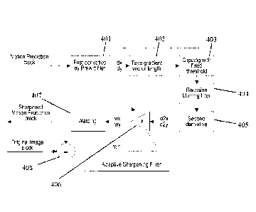
Fig. 7 shows a sharpening adaptation according to an embodiment of the
present invention. The sharpening adaptation process shown in Fig. 7 is
carried out on
the video coder side.
The estimation of the adaptive parameter(s) of the sharpening filter as well
as
necessity of sharpening itself, i.e. the decision to apply or bypass the
adaptive
sharpening filter, can be performed together with the motion estimation
procedure. Fig.
7 illustrates how the adaptive sharpening parameter(s) can be obtained during
the
evaluation of motion vector candidates. The following steps can then be
performed:
- take the motion vector to be analysed,
- obtain motion interpolated block 708 by applying a conventional
interpolation
filter 709,
- perform the sharpening filter adaptation 707 so as to obtain the optimal
adaptation parameter(s) for the sharpening filter,
- apply the sharpening filter 706 with optimal parameter(s) found in the
previous step to obtain sharpened prediction block 705,
- decide or evaluate 704 if the sharpened prediction block is better that
the
SUBSTITUTE SHEET (RULE 26)
CA 02999700 2018-03-22
WO 2017/052406 PCT/RU2015/000611
23
prediction block without sharpening, wherein this decision/evaluation is based
on a
rate-distortion optimization and is transmitted to the video decoder by means
of the
sharpening filter information added as signalling data or side information to
the
encoded video bit stream. This sharpening filter information is identified in
Fig. 7 as
sharpening on/off.
If the video coder 200 decides to apply a sharpened prediction, then also
adaptive parameter information reflecting the value of the optimal
parameter(s) of the
sharpening filter is added as signalling data to the encoded video bit stream.
The
adaptive parameter information is identified in Fig. 7 as sharpening strength.
The sharpening adaptation shown in Fig. 7 can be applied at different steps of
the motion estimation loop. Fig. 8 shows three possible embodiments for
integrating
the sharpening adaptation process into the motion vector search.
In the embodiment of Fig. 8a, the sharpening adaptation ¨ i.e. finding the
optimal coefficient k ¨ is performed for each possible motion vector
candidate. This
embodiment provides the best possible quality at the cost of searching
complexity.
Correspondingly, the motion estimation 800 of Fig. 8a comprises a sharpening
filter adaptation 803 for each motion vector candidate 801. For a motion
vector
candidate, the prediction block is obtained 802, the adaptive sharpening is
performed
803 and a decision is taken whether the sharpening filter shall be applied or
bypassed
804. This procedure is repeated for each possible motion vector candidate.
In the embodiment of Fig. 8c, the sharpening adaptation is alternatively
performed only for one motion vector, i.e. for the best motion vector that is
found
during the motion estimation. This embodiment is advantageous in that it
reduces the
search complexity. On the other hand, the found sharpened prediction block may
not
be the best possible.
Correspondingly, the motion estimation 820 of Fig. 8c comprises only one
sharpening adaptation step 825. Based on this sharpening adaptation 825, it
can be
decided whether the adaptive sharpening filter shall by applied or
bypassed826. Prior
to the sharpening adaptation 825, an integer motion vector search 822 is
carried out for
each motion vector candidate 821, and a fractional motion vector search 824 is
carried
out for each fractional position 823.
The embodiment shown in Fig. 8b is a balanced solution between the
SUBSTITUTE SHEET (RULE 26)
CA 02999700 2018-03-22
WO 2017/052406
PCT/RU2015/000611
24
embodiments of Figs. 8a and 8c: the sharpening adaptation is performed only
during
the fractional motion vector refinement. In this embodiment, the integer
motion vector
search is performed without sharpening adaptation to reduce the search
complexity.
Correspondingly, the motion estimation 810 of Fig. 8b comprises an integer
motion vector search 812 that is carried out for each motion vector candidate
811.
Once the integer motion vector search is done 812, the obtained prediction
block is
interpolated 814 for each fractional position 813: a sharpening adaptation 815
is
performed for each prediction block, and it is decided 816 for each prediction
block
whether the sharpening filter shall be applied or bypassed.
The present invention has been described in conjunction with various
embodiments as examples as well as implementations. However, other variations
can
be understood and effected by those persons skilled in the art and practicing
the
claimed invention, from the studies of the drawings, this disclosure and the
independent claims. In the claims as well as in the description the word
"comprising"
does not exclude other elements or steps and the indefinite article "a" or
"an" does not
exclude a plurality. A single element or other unit may fulfil the functions
of several
entities or items recited in the claims. The mere fact that certain measures
are recited in
the mutual different dependent claims does not indicate that a combination of
these
measures cannot be used in an advantageous implementation.
25
SUBSTITUTE SHEET (RULE 26)