Note: Descriptions are shown in the official language in which they were submitted.
DIFFERENTIAL PRESSURE ACTUATION TOOL AND METHOD OF USE
INVENTORS: JOSHUA REID CAMPBELL, CHRISTIAN FAY
APPLICANT: CHARLES ABERNATHY ANDERSON
CROSS REFERENCES
[0001] This Application claims priority to United States Provisional
Patent
Application No. 62/480,751, entitled "Differential Pressure Actuator and
Method of
Use", filed April 3, 2017.
FIELD
[0002] Embodiments disclosed herein generally relate to downhole tools
for use in
wellbores, and more specifically to the use of downhole agitation tools used
to aid in
progressing downhole milling operations within the wellbore.
BACKGROUND
[0003] In the drilling and reworking of wellbores in the oil and gas
industry,
downhole tools known as packers or plugs are commonly used to temporarily seal
the
wellbore, and then removed from the wellbore such that operations can
continue.
Although the packers or plugs could potentially be retrieved, it is often
simpler and
less expensive to mill or drill the tools from the wellbore. Such processes,
however,
are relatively slow, particularly where one or more plugs need to be removed
and
there are significant distances traveled by the milling tools in between the
plugs.
[0004] It is also difficult to extend milling tools long distances down
a wellbore in
order to reach plugs positioned deep within the wellbore. By way of example,
where it
can only take a few minutes to mill a plug, it can take a few hours to move
the milling
tool between the plugs. Unfortunately, mill times and travel times tend to
increase
over the course of the well.
1
CA 3000012 2018-04-03
[0005] There is a need for improved milling process, such processes
operative to
reduce travel time in between milling and/or drilling operations for removing
downhole packers and plugs.
SUMMARY
[0006] According to a broad aspect of the present disclosure, there is
provided a
tool connectable to a tubing string for enhancing agitation of a downhole
apparatus,
the tool comprising: a housing having an axial bore extending therethrough
between a
housing inlet and a housing outlet, and two or more flow passages defined
therein
uphole from the housing outlet; and a piston movable in the bore of the
housing
between a first position and a second position, the piston having an axial
bore
extending therethrough between a piston inlet and a piston outlet, the piston
inlet
being in fluid communication with the bore of the housing, and in the first
position,
the bore of the piston is in fluid communication with the two or more flow
passages
via the piston outlet; and in the second position, the piston blocks fluid
communication to at least one of the two or more flow passages, and the bore
of the
piston is only in fluid communication with the remainder of the two or more
flow
passages via the piston outlet, wherein the piston is transitionable between
the first
and second positions by alternately introducing or increasing fluid flow to
the housing
via the housing inlet and ceasing or decreasing the fluid flow to the housing
via the
housing inlet, and wherein the fluid flow flows through at least some of the
flow
passages before exiting the tool.
[0007] According to another broad aspect of the present disclosure,
there is
provided a method of enhancing agitation of a downhole apparatus on a tubing
string,
the method comprising: providing a tool on the tubing string near the downhole
apparatus, the tool comprising a housing having an axial bore extending
between a
housing inlet and a housing outlet and two or more flow passages defined
therein; and
a piston movable in the housing between a first position and a second
position, the
piston having an axial bore between a piston inlet and a piston outlet, the
piston inlet
being in fluid communication with the bore of the housing; introducing or
increasing
fluid flow to the housing via the housing inlet to move the piston axially in
a direction
2
CA 3000012 2018-04-03
to place the piston in the first or second position, wherein in the first
position, the
bore of the piston is in fluid communication with the two or more flow
passages via
the piston outlet; and in the second position, the piston blocks fluid
communication to
at least one of the two or more flow passages, and the bore of the piston is
only in
fluid communication with the remainder of the two or more flow passages via
the
piston outlet; ceasing or decreasing the fluid flow to the housing to move the
piston
axially in a second direction opposite to the first direction; introducing or
increasing
the fluid flow to the housing via the housing inlet to move the piston axially
to
transition the piston from the first position to the second position or from
the second
position to the first position.
[0008] According to yet another broad aspect of the present disclosure,
there is
provided a tool connectable to a tubing string, the tool comprising: a housing
having
an axial bore extending therethrough between a housing inlet and a housing
outlet,
and a first flow passage and a second flow passage defined therein uphole from
the
housing outlet; and a piston movable in the bore of the housing between a
first
position and a second position, the piston having an axial piston bore, a
piston inlet,
and a piston outlet, the piston bore being in fluid communication with the
bore of the
housing via the piston inlet, and in the first position, the piston blocks
fluid
communication to the second flow passage and the piston bore is in fluid
communication with the first flow passage via the piston outlet; and in the
second
position, the piston blocks fluid communication to the first flow passage and
the
piston bore is in fluid communication with the second flow passage via the
piston
outlet, wherein the piston is transitionable between the first and second
positions by
alternately introducing or increasing fluid flow to the housing via the
housing inlet
and ceasing or decreasing the fluid flow to the housing via the housing inlet,
and
wherein in the first position the fluid flow flows through the first flow
passage before
exiting the tool, and wherein in the second position the fluid flow flows
through the
second flow passage before exiting the tool.
[0009] According to another broad aspect of the present disclosure,
there is
provided a method comprising: providing a tool on a tubing string, the tool
comprising a housing having an axial bore extending between a housing inlet
and a
3
CA 3000012 2018-04-03
housing outlet and a first flow passage and second flow passage defined
therein; and a
piston movable in the housing between a first position and a second position,
the
piston having a piston bore, a piston inlet, and a piston outlet, the piston
bore being in
fluid communication with the bore of the housing via the piston inlet;
introducing or
increasing fluid flow to the housing via the housing inlet to move the piston
axially in
a direction to place the piston in the first or second position, wherein in
the first
position, the piston blocks fluid communication to the second flow passage and
the
piston bore is in fluid communication with the first flow passage via the
piston outlet;
and in the second position, the piston blocks fluid communication to the first
flow
passage and the piston bore is in fluid communication with the second flow
passage
via the piston outlet; ceasing or decreasing the fluid flow to the housing to
move the
piston axially in a second direction opposite to the first direction;
introducing or
increasing the fluid flow to the housing via the housing inlet to move the
piston
axially to transition the piston from the first position to the second
position or from
the second position to the first position.
DESCRIPTION OF THE DRAWINGS
[0010] The invention will now be described by way of an exemplary
embodiment
with reference to the accompanying simplified, diagrammatic, not-to-scale
drawings.
Any dimensions provided in the drawings are provided only for illustrative
purposes,
and do not limit the invention as defined by the claims. In the drawings:
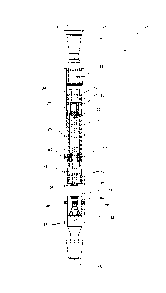
[0011] Figure 1 is a cross sectional side view of the present tool
according to one
embodiment herein, the tool shown in a first (low pressure) position;
[0012] Figure 2 is a cross sectional side view of the present tool
according to one
embodiment herein, the tool shown in a second (high pressure) position;
[0013] Figure 3A and 3B are a first side view and a second side view,
respectively, of the present tool according to embodiments herein, with the
top portion
omitted and the housing shown in cross-section, and the tool being shown in
the first
4
CA 3000012 2018-04-03
(low pressure) position. Figures 3A and 3B are sometimes collectively referred
to
herein as Figure 3;
[0014] Figures 4A and 4B are a first perspective view and a second
perspective
view, respectively, of the tool depicted in Figure 3, with the housing and the
bearing
assembly omitted. Figures 4A and 4B are sometimes collectively referred to
herein as
Figure 4;
[0015] Figures 5A and 5B are a first zoomed in perspective view and a
second
zoomed in perspective view, respectively, of the tool depicted in Figure 3,
with the
housing omitted and the bearing assembly shown in phantom lines. Figures 5A
and
5B are sometimes collectively referred to herein as Figure 5;
[0016] Figures 6A and 6B are cross sectional zoomed in side views of the
present
tool showing an example valve configuration in the first position depicted in
Figure 1
and in the second position depicted in Figure 2, respectively. Figures 6A and
6B are
sometimes collectively referred to herein as Figure 6.
[0017] Figure 7 is a cross sectional perspective view of a bearing assembly
of the
present tool;
[0018] Figures 8A and 8B are a top view and a cross sectional
perspective view,
respectively, of a valve seat of the present tool according to embodiments
herein.
Figures 8A and 8B are sometimes collectively referred to herein as Figure 8;
[0019J Figures 9A and 9B are cross sectional zoomed in side views of the
present
tool according to another embodiment herein, the tool shown in a first (low
pressure)
position and a second (high pressure) position, respectively. Figures 9A and
9B are
sometimes collectively referred to herein as Figure 9; and
[0020] Figures 10A and 10B are cross sectional zoomed in side views of
the
present tool according to yet another embodiment herein, the tool shown in a
first
bypass position and a second flow-through position, respectively. Figures 10A
and
10B are sometimes collectively referred to herein as Figure 10.
5
CA 3000012 2018-04-03
DESCRIPTION OF EMBODIMENTS
[0021] When describing the present invention, all terms not defined
herein have
their common art-recognized meanings. To the extent that the following
description
is of a specific embodiment or a particular use of the invention, it is
intended to be
illustrative only, and not limiting of the claimed invention. The following
description
is intended to cover all alternatives, modifications and equivalents that are
included in
the spirit and scope of the invention, as defined in the appended claims.
[0022] According to embodiments herein, improved apparatus and
methodologies
for improving milling times of downhole packers, plugs, or the like are
provided.
[0023] By way of background, many tools for inducing movement of a
downhole
apparatus are known, and are collecting referred to herein as 'agitator'
tools. Some
such agitator tools include Applicant's own technology disclosed in United
States
Patent No. 9,222,312, incorporated herein in its entirety by reference, which
uses a
variable restrictor in the fluid flow to vent a small amount of fluid from the
tool to the
annulus, reducing the pressure within the tool and creating a negative
pressure pulse
(i.e. an axial mechanical force, or a fluid hammer effect). The fluid hammer
effect
generates hydraulic inertial forces that produce an impact energy pulse,
improving the
overall weight transfer of the tool. Such tools can reduce static friction
(i.e. drag)
within the wellbore and enable more efficient transfer of weight onto the bit.
When
used in milling operations, such tools advantageously achieve substantially
consistent
mill times along the length of the wellbore. It is believed that such
advantages are at
least partially the result of the variable restriction in the fluid flow and
also the
periodic venting of the built-up differential pressure (created by the milling
motor)
between the agitator tool/tubing string and the annulus. However, because the
milling
motor is not in operation when the downhole tools (e.g. tubing string) are
travelling
between plugs, no differential pressure is created. There is a need for a
downhole tool
operative to generate a differential pressure substantially similar to the
differential
pressure typically generated by the milling motor, thereby serving to achieve
the
above-referenced advantages when the milling motor is turned off.
6
CA 3000012 2018-04-03
[0024] A pressure actuation tool 10 is provided herein for selectively
providing a
differential pressure between the tubing string and the annulus in a zone at
or above
the tool, so as to facilitate more effective operation of an agitation tool
located uphole
therefrom and/or to function as a stand-alone agitation tool. According to
embodiments herein, the present tool may be configured as a sub adapted at its
upper
(uphole) and lower (downhole) ends to be incorporated into any drilling fluid
transmitting downhole tubulars positioned within a subterranean wellbore
including,
without limitation, drill string, coil tubing, casing string, etc.,
collectively referred to
herein as tubing strings. Tool 10 may be utilized to agitate the downhole
tubulars, and
may operate alone or in combination with other downhole tools such as
vibration or
agitation tools, milling tools, hammer subs, etc.
[0025] Having regard to Figs. 1 and 2, sub 10 comprises a tubular
housing 12
having a longitudinal bore 14 extending therethrough for transmitting drilling
fluid
through the downhole tubulars. The bore 14 has a central axis x, an upper
(uphole)
inlet end 13, and a lower (downhole) outlet end 15. Inlet and outlet ends
13,15 can
include interior or exterior threading, or other such connection means known
in the
art, for connecting the housing 12 to the downhole tubulars (not shown).
Connections
may be of conventional type, such as pin/box type to facilitate ready
connection with
the downhole tubulars. Housing 12 may be of steel construction, or any other
suitable
material, and can be surface hardened for durability and abrasion resistance.
[0026] Housing 12 is configured to receive a reciprocating valve 20 in
bore 14.
Valve 20 is a hydraulically actuated piston, reciprocated between a first, low-
pressure
position (Fig. 1) and a second, high-pressure position (Fig. 2), as described
in more
detail below. Valve 20 may also be referred to herein as a piston. Positioning
of the
valve 20 in the first or second position may be selectively controlled by
adjusting the
fluid flow into bore 14, which may be accomplished using pumps (not shown) to
transmit drilling fluids through bore 14 at varying rates.
[0027] In the illustrated embodiment, valve 20 comprises a generally
cylindrical
tubular body 21 that is axially movable within bore 14 of housing 12. Body 21
has a
valve bore 22 extending axially therethrough and in fluid communication with
bore
14. Body 21 has an upper portion 24 and a lower portion 28, having outer
diameters
7
CA 3000012 2018-04-03
substantially equal to or smaller than the inner diameter of bore 14. Valve 20
can thus
freely reciprocate axially within bore 14.
[0028] The outer surface of upper and lower portions 24,28 of body 21 is
configured to provide annular grooves 30 for seating annular seals 32, such as
annular
0-rings or other seals known in the art. When seated in grooves 30, seals 32
sealingly
engage the inner surface of bore 14, thereby preventing fluid flow
therebetween. It is
contemplated that upper portion 24 may be a discrete member from the portions
of
valve 20 therebelow. In alternative embodiments, upper portion 24 may be
integral
with the portions of valve 20 therebelow.
[0029] Valve 20 has a valve plug 34 extending axially from the lower end of
lower portion 28. Plug 34 has an axially extending plug bore 35 defined
therein, in
fluid communication with bore 22 for expelling fluid flowing through bores
14,22
from the lower end of lower portion 28. In some embodiments, bore 35 may have
an
inner diameter that is substantially equal to that of bore 22. The outer
diameter of plug
34 may be substantially smaller than the outer diameter of lower portion 28,
such that
plug 34 can correspondingly engage a valve seat 80 therebelow (described in
more
detail below). The outer surface of the plug 34 may be configured to have plug
grooves 31 for seating annular plug seals 33, such that plug 34 sealingly
engages seat
80 to prevent fluid flow through the tool 10 (See Figs. 2 and 6B).
[0030] Body 21 has a middle portion 26 having an outer diameter
substantially
smaller than the inner diameter of bore 14 and the outer diameter of upper and
lower
portions 24,28. The outer surface of middle portion 26 has defined thereon a
cam
actuation area 38 which comprises an annular teeth forming groove for guiding
axial
and rotational movement of valve 20. More specifically, as will be described
in more
detail, cam actuation area 38 serves to rotate valve 20 by an angle about the
central
axis upon each axial reciprocation of the valve 20 within bore 14. In some
embodiments, valve 20 may further comprise an annular bearing assembly 50 and
a
spring 70, supported on the outer surface of middle portion 26.
[0031] According to embodiments herein and with reference to Figs 1 to
6, the
annular groove in the cam actuation area 38 defines a plurality of
corresponding upper
8
CA 3000012 2018-04-03
teeth 40 and lower teeth 46, radially intermittently positioned around the
outer surface
of the middle portion 26. Each upper tooth 40 is an apex portion having a peak
41.
The upper teeth 40 are separated by alternating deep and shallow slots 42d,
42s. The
depth of the slots 42d, 42s is the length between the peak 41 of the tooth and
the
trough of the slot 42d, 42s. The deep slots 42d have a larger depth than the
shallow
slots 42s and thus extend further towards upper portion 24 (i.e. in an uphole
direction)
than shallow slots 42s.
[0032] Both the deep and shallow slots 42d,42s are sized for slidably
receiving a
cam 64 therein. It should be understood by a skilled person that the depth of
both deep
and shallow slots 42d,42s may be predetermined and selected as desired based
upon
the distance of the valve 20 from valve seat 80, such that the receipt of cam
64 in the
deep slots 42d enables valve 20 to extend sufficiently downwardly for plug 34
to
sealingly engage with valve seat 80 therebelow, whereas the receipt of cam 64
in the
shallow slots 42s may prevent same (as described in more detail below).
[0033] Each lower tooth 46 is an apex portion having a peak 47. Adjacent
lower
teeth 46 are separated by a valley 48. The upper and lower teeth 40,46 can be
oriented
such that the peaks 41 are radially aligned with the valleys 48, and the peaks
47 are
radially aligned with the slots 42d, 42s. The peaks, slots, and valleys are
directional
(i.e. asymmetrical) and shaped to alternatingly advance cam 64 to the next set
of slots
42d,42s and valleys 48 as valve 20 is reciprocated axially inside bore 14 of
housing
12. In some embodiments, teeth 40 and/or teeth 46 each have an angled profile
that is
shaped as a cam guide.
[0034] While the valve 20 in the illustrated embodiment has four upper
teeth 40
and four lower teeth 46, the valve 20 may have fewer or more upper and lower
teeth
in other embodiments.
[0035] With reference to Figs. 1 to 3 and 7, bearing assembly 50 is
positioned
inside housing 12 between the upper end 24 and lower end 26 of valve 20. As
best
shown in Figs. 6, 8, and 9, bearing assembly 50 comprises an annular member 51
having a rotatable inner ring 52 and a stationary outer ring 54. A lower
portion of the
outer ring 54 is configured to slidably receive at least an upper portion of
inner ring
9
CA 3000012 2018-04-03
52 in a coaxially overlapping manner, while a least a lower portion of inner
ring 52
extends downwardly from the lower end of the outer ring 54. When the upper
portion
of inner ring 52 is received in the lower portion of outer ring 54, an annular
channel
57 is defined between the inner and outer rings 52, 54. The channel 57 is
configured
to receive and support a plurality of ball bearings 58 therein. As would be
understood,
bearing assembly 50 may be secured to housing 12 via any appropriate securing
means known in the art such as, for example, via bolts threaded through
apertures 60
in housing 12 and, at least partially, through corresponding apertures 61 in
outer ring
54.
[0036] In some embodiments, outer ring 54 has an internal annular recess 53
for
slidably receiving inner ring 52. As such, outer ring 54 may be adapted to
have a
smaller internal diameter at its upper (uphole) portion versus it lower
(downhole)
portion, the difference in internal diameters thereby defining the annular
recess 53
with an annular shoulder 56. When inner ring 52 is slidably received within
outer ring
54, the upper (uphole) end of inner ring 52 is adjacent to and may be in
abutment with
shoulder 56. The lower portion of inner ring 52 extending axially downwardly
from
outer ring 54 has at least one cam 64 protruding radially therefrom. In some
embodiments, cam 64 is a substantially cylindrical member positioned at a
radial
location of the inner ring 52 and extends radially inwardly from the inner
surface of
the inner ring 52 into the cam actuation area 38. Cam 64 is sized and shaped
to
correspondingly engage slots 42d,42s and valleys 48. In some embodiments, cam
64
may be provided in inner ring 52 by inserting an elongated substantially
cylindrical
member through a radially positioned hole in inner ring 52 such that an axial
portion
of the member extends radially inwardly from the inner surface of the inner
ring 52.
The elongated member may be secured to the inner ring 52 by welding or other
methods known in the art.
[0037] In some embodiments, the positions of the cam and the upper and
lower
teeth, slots, and valleys may be reversed such that the cam is on the outer
surface of
the valve 20, extending radially outwardly therefrom, while the upper and
lower teeth,
slots, and valleys are defined on the inner surface of the bearing assembly.
CA 3000012 2018-04-03
[0038] While the outer ring 54 has the internal annular recess 53 in the
illustrated
embodiment, other configurations are possible. For example, the inner ring 52
may
have an external annular recess for receiving an axial portion of the outer
ring 54, or
both the inner and outer rings 52,54 may have corresponding annular recesses
on their
outer and inner surfaces, respectively, for receiving an axial portion of one
another.
[0039] Having specific regard to Fig. 7, inner ring 52 has an annular
groove 57 on
its outer surface and outer ring 54 has an annular groove 59 on its inner
surface that
corresponds to the annular groove 57. When aligned, the annular grooves 57,59
together form a circumferential channel 55 for receiving and containing the
plurality
of ball bearings 58 therein. As would be understood, channel 55 may be
appropriately
sized to enable inner ring 52 to freely rotate about central axis x, while
outer ring 54
remains stationary (and securely affixed to housing 12).
[0040] Returning to Figs. 1 to 6, spring 70 encompasses middle portion
26,
between upper and lower portions 24,28. It should be understood that spring 70
may
be positioned in abutting relationship with bearing assembly 50, and more
specifically
may be positioned to rest on the upper surface of annular member 51. As such,
valve
may be spring-biased in an upward direction, such that when the spring 70 is
compressed, it exerts an upward force on valve 20 (i.e. away from valve seat
80). As
would be known, the configuration of spring 70 may be selected based upon a
20 predetermined size and the desired compression/tension. When no external
force is
applied on valve 20, spring 70 may be configured such that the cam 64 is
positioned
within one of the valleys 48 of lower teeth 46. Spring 70 may have a linear or
progressive spring rate.
[0041] With reference to Figs. 1 to 5 and as best shown in Fig. 8, the
present
actuation tool 10 further comprises valve seat 80, positioned at or near the
outlet end
15. Valve seat 80 has a central bore 82 extending therethrough and one or more
circumferentially positioned passages 84 located on the outer surface thereof.
In the
illustrated embodiment, each passage 84 extends generally axially along the
length of
valve seat 80. Radial passages 84 can follow a linear, helical, or any other
fluid flow
path, provided that they fluidly connect the space above and below the valve
seat 80.
Valve seat 80 may be securely affixed to housing 12 via any appropriate means
as
11
CA 3000012 2018-04-03
would be known in the art. For example, a bolt 87 may be threaded through an
aperture 86 in housing 12 and at least partially into a corresponding valve
seat
aperture 88 at a radial position on the outer surface of valve seat 80 other
than the
passages 84.
[0042] At its upper end, central bore 82 is sized and shaped to receive
valve plug
34 so as to form a substantially fluid-tight connection therewith. According
to
embodiments herein, central bore 82 may have a frustoconically shaped lower
end,
such that the inner diameter of bore 82 increases towards the downhole end of
the
valve seat 80 (See Fig. 8B). The frustoconical shape of bore 82 may reduce
fluid
backflow (e.g. eddies) created by fluid flow through the passages 84, which
may
decrease the rate of erosion of the components. In alternative embodiments,
valve seat
80 may be otherwise configured, such as in an opposed fashion wherein the
valve seat
80 has a valve plug extending upwardly therefrom towards inlet end 13 and
lower
portion 28 of valve 20 is configured at to receive the valve plug therein.
[0043] In the low pressure position, as shown in Fig. 1, the central bore
82 is in
fluid communication with valve bore 22 via bore 14 of the housing 12 and with
the
one or more passages 84 at or near the lower end of bore 82. Further, the
passages 84
are also in fluid communication with valve bore 22 via bore 14. In the high
pressure
position, as shown in Fig. 2, only central bore 82 is in fluid communication
with valve
bore 22, while fluid communication with passages 84 is blocked.
[0044] According
to embodiments herein, the present agitation tool 10 may be
assembled as follows:
(i) with the top portion 11 uncoupled from housing 12 to permit open access
to bore 14, valve seat 80 is inserted into bore 14 with its apertures 88 in
alignment with corresponding apertures 86 of the housing 12 such that bolt
87 can be threaded therethrough to secure the seal seat 80 to housing 12;
(ii) valve 20 can be assembled, with upper portion 24 uncoupled from and
with lower portion 28 coupled to middle portion 26, by sliding the inner
and outer rings 52,54 on to the middle portion, such that the rings 52,54
encircle middle portion 26 about the cam actuation area 38. One or more
12
CA 3000012 2018-04-03
cams 64 is inserted through holes in the inner ring 52 such that the cams
engage one of the slots 42s,42d or valleys 48 and the cams are secured to
the inner ring 52;
(iii) spring 70 slides on to the valve 20 to coil around middle portion 26
and
then upper portion 24 is coupled to middle portion 26 to secure the bearing
assembly 50 and spring 70 between upper and lower portions 24,26;
(iv) once assembled, valve 20 is inserted into and positioned within bore
14
above valve seat 80, until the apertures 61 of the outer ring 54 are aligned
with the apertures 60 of housing 12, and then bolts are threaded through
both apertures to secure the bearing assembly 50 to the housing 12; and
(v) top portion 11 is then coupled at the upper end of housing 12 and the
assembled tool 10 can be installed on a tool string near and/or below an
agitator.
[0045] Tool 10
can be hydraulically-actuated between a first, low-pressure
position (Figs. 1 and 6A) and a second, high-pressure position (Figs. 2 and
6B). In
operation, tool 10 is positioned on a tool string substantially at or below
the agitator
tool operative to vibrate the string. Having regard to Fig. 1, drilling fluids
are
introduced to tool 10 via fluid inlet 13 and flow through bore 14 of housing
12, bore
22 of valve 20, bore 82 of valve seat 80, and exit tool 10 via fluid outlet
15.
Depending on the position of valve 20, some of the drilling fluids may also
flow
through passages 84 before exiting fluid outlet 15. The position of valve 20
can be
changed by repeated introduction of or increasing fluid flow through inlet 13.
The
repeated introduction or increase of fluid flow into tool 10 may exert enough
force to
compress spring 70, thereby displacing valve 20 axially downhole, whereas
ceasing or
decreasing fluid flow reduces the force exerted on spring 70, thereby
releasing spring
70 and allowing valve 20 to revert axially uphole. Depending on the frequency
and/or
rate of the fluid flow into tool 10, valve 20 can be displaced axially
downhole until
valve plug 34 engages valve seat 80, thereby blocking fluid flow to passages
84 while
all the fluids from bore 22 flow into and through bore 82 of valve seat 80.
Valve 20
thus acts as a piston within tool 10. Accordingly, tool 10 is in the first,
low-pressure
13
CA 3000012 2018-04-03
position when drilling fluids flow through bore 82 and passages 84, and is in
the
second, high-pressure position when passages 84 are blocked and drilling
fluids only
flow through bore 82.
[0046] More specifically, having further regard to Fig. 6, as valve 20
moves
axially downhole due to an introduction or increase in fluid flow into tool
10, upper
teeth 40 descend downwardly, and due to their angled cam profiles, teeth 40
cause
inner ring 52 to rotate as the teeth 40 engage cams 64 until cams 64 are
received
within slots 42d or slots 42s.
[0047] When cams 64 are received within the deeper slots 42d, tool 10 is
in the
second, high-pressure position, wherein valve 20 has been actuated downwardly
and
driven into valve seat 80 such that valve plug 34 forms a fluid-tight
connection with
bore 82 of valve seat 80. In the second, high-pressure position, spring 70 is
energized
as it is compressed between the upper portion 24 and bearing assembly 50. In
the
second, high-pressure position, the fluid flowing into tool 10 flows through
bore 22 of
valve 20 and then through bore 82 of valve seat 80, thereby generating a zone
of high
pressure in the tool string and coil tubing above tool 10. This resulting high
pressure
. zone increases the pressure differential between the inside of the coil
tubing and
agitator uphole from tool 10, which may help the agitator operate more
effectively
while the tool string is travelling downhole.
[0048] When cams 64 are received within the shallower slots 42s, tool 10 is
in the
first, low-pressure position, wherein valve 20 is still driven down by the
incoming
fluid to energize spring 70, but fails to actuate downwardly far enough to
sealingly
engage valve seat 80. As such, in the first, low-pressure position, no fluid-
tight
connection is created between the valve plug 34 and bore 82 so fluid flowing
into tool
10 flows through bore 22 of valve 20 and then through bore 82 and passages 84
of
valve seat 80. As there is a greater rate of fluid flow past the valve seat
80, there is
less pressure generated in the uphole tool string and coil tubing than in the
second
position. Advantageously, the pressure differential in the coil tubing and
tool string is
still high enough for the agitator to create the desired fluid hammer effect,
as the
motor creates the desired pressure differential in the coil tubing in place of
the tool 10.
14
CA 3000012 2018-04-03
Actuation of tool 10 into the first low-pressure position while running the
motor is
necessary; otherwise, the pressure in the coil tubing may be too high to run
the motor.
[0049] To actuate tool 10 from the second high-pressure position to the
first low-
pressure position, and vice versa, fluid flow is first stopped or decreased
such that
valve 20 is spring-biased axially uphole by the release of potential energy of
the
energized spring 70. As the valve 20 moves axially uphole, cams 64 slide out
of slots
42d,42s and meet the angled cam profiles of lower teeth 46, which causes inner
ring
52 to rotate as cams 64 are received in valleys 48. Fluid flow into tool 10 is
then
started again or increased to drive valve 20 downhole, which also drives ,cams
64 into
the angled cam profiles of upper teeth 40, thereby rotating inner ring 52 as
cams 64
are received in the next set of slots 42s,42d. Since slots 42s,42d alternate
between
deep 42d and shallow 42s about the valve 20, if the cams 64 were previously
received
in the deep slots 42d, they will be received in the shallow slots 42s when the
tool is
re-actuated, and vice versa. In this manner, fluid flow into tool 10 can be
stopped or
decreased and then started or increased to actuate valve 20 and rotate inner
ring 52
until the cams 64 are received in the desired slots 42s,42d to accordingly
place tool 10
in the desired operating position.
[0050] In some embodiments, housing 12 may include radial ports (not
shown)
above and proximate to the valve seat 80 in addition to, or as an alternative
to,
passages 84. When the tool 10 is in the second high-pressure position, valve
20 fluidly
seals the radial ports to prevent fluid communication between bore 14 of
housing 12
and the annulus. When tool 10 is in the first low-pressure position, fluid in
the tool 10
flows into the annulus via the radial ports as well as downhole through bore
82 and
outlet 15. The radial ports, bore 82, and passages 84 may be individually or
collectively referred to herein as flow passages.
[0051] A tool 100 according to another embodiment is shown in Fig. 9.
Reference
numerals of the components in Fig. 9 are the same as assigned for like
components of
tool 10 and new reference numerals are provided for differing components. Tool
100
has a valve seat 180 that is different from the valve seat 80 of tool 10.
Valve seat 180
has a through bore 82 and, in lieu of radial passages 84, valve seat 180 has
one or
more side bores 184 each in fluid communication with the outer surface of
housing 12
CA 3000012 2018-04-03
via a radial port 190 provided in the wall of housing 12. Side bores 184 and
radial
ports 190 may be individually or collectively referred to herein as flow
passages.
[0052] Fig. 9A illustrates the tool 100 in a first low-pressure position
wherein
fluid in bore 22 exits valve 20 at plug bore 35 and flows into the annulus via
the one
or more side bores 184 and radial ports 190, respectively, as well as downhole
through bore 82 of seat valve 180 and outlet 15. In Fig. 9A, the flow path of
the fluid
in the first low-pressure position is denoted by the reference character F.
=
[0053] Fig. 9B illustrates the tool 100 in a second high-pressure
position wherein
valve 20 is shifted down to engage seat valve 180, thereby blocking the side
bores 184
to prevent any fluid in tool 100 from entering the annulus via radial ports
190. In the
second high-pressure position, all the fluid flow is directed downhole through
bore 82
and outlet 15, respectively. In Fig. 9B, the flow path of the fluid in the
second high-
pressure position is denoted by the reference character F'. It can be
appreciated that
tool 100 can be transitioned between the first low-pressure position and the
second
high-pressure position in the manner described above with respect to tool 10.
[0054] In some embodiments, the tool may be configured to block all or
substantially all fluid from flowing downhole in one of the two positions. For
example, a tool 200 shown in Fig. 10 has two positions ¨ a first bypass
position and a
second flow-through position. Reference numerals of the components in Fig. 10
are
the same as assigned for like components of tool 10, 100 and new reference
numerals
are provided for differing components. In the bypass position, all or
substantially all
fluid in the tool 200 is directed to the annulus, thereby restricting fluid
flow
downhole, for example, to the motor. In the flow-through position,
substantially all or
some of the fluid in the tool can flow downhole via outlet 15.
[0055] In a sample embodiment, tool 200 includes a valve seat plug 282 for
restricting fluid flow through the bore 82 of valve seat 180 when the tool 200
is in the
first bypass position. Plug 282 has an elongated body, and an inner bore 283
defined
in the body extending between an upper open end 284 and a lower closed end
286.
Plug 282 also has one or more radial exit ports 288 defined at an axial
location of the
body between ends 284, 286 to allow fluid communication between the inner bore
and
16
CA 3000012 2018-04-03
the outer surface of the plug 282. The open end 284 is connected to the
downhole end
of valve 20 such that inner bore 283 and exit ports 288 are in fluid
communication
with bore 22. The body of plug 282 extends downwardly from the valve 20 into
bore
82 of seat valve 180 and is slidably movable in bore 82 as the tool 200
transitions
between positions. Plug 282 is configured to form a seal in bore 82 of the
seat valve
180 when the tool 200 is in the bypass position to restrict fluid flow
downhole. In the
illustrated embodiment, the lower closed end 286 is enlarged and is shaped
(e.g.
frustoconically shaped) for matingly plugging the bore 82 at or near the
downhole
end. Ports 288 are located on the body of plug 282 such that they are in fluid
communication with ports 190 via bore 14 and side bores 184 when the tool 200
is in
the bypass position and with bore 82 of the seat valve 180 when the tool 200
is in the
flow-through position.
[0056] Fig. 10A illustrates the tool 200 in the bypass position wherein
valve 20 is
spaced apart from seat valve 180 such that lower end 286 of plug 282 engages
the seat
valve 180 to plug bore 82. Accordingly, in the bypass position, all or
substantially all
the fluid in bore 22 of valve 20 flows into the annulus via bore 283, ports
288, side
bores 184, and ports 190, respectively. In Fig. 10A, the flow path of the
fluid in the
first bypass position is denoted by the reference character F.
[0057] Fig. 10B illustrates the tool 200 in the second flow-through
position
wherein valve 20 is shifted down to (i) disengage lower end 286 of plug 282
from seat
valve 180, thereby allowing fluid communication between inner bore 283 and
outlet
15 via ports 288; and (ii) engage the seat valve 180, thereby blocking the
side bores
184 and cutting fluid communication between ports 288 and bores 184 to prevent
any
fluid in tool 200 from entering the annulus via radial ports 190. In the flow-
through
position, all the fluid flow in bore 22 is directed downhole through bore 283,
ports
288, and outlet 15, respectively. In Fig. 10B, the flow path of the fluid in
the second
flow-through position is denoted by the reference character F'.
[0058] In other words, in the first position, all or substantially all
of the fluids
entering the tool 200 are directed to flow through side bores 184 and ports
190 before
exiting into the annulus, and in the second position, all or substantially all
of the fluids
17
CA 3000012 2018-04-03
entering the tool 200 are redirected to flow through bore 82 of the seat valve
180
before exiting the tool via outlet 15.
[0059] The use of plug 282 is only one way of restricting and/or
directing fluid
flow downhole in the bypass position of tool 200. It can be appreciated that
other
ways of restricting fluid flow downhole in the bypass position are possible.
It can also
be appreciated that tool 200 can be transitioned between the bypass position
and the
flow-through position in the manner described above with respect to tool 10.
Accordingly, tool 200 allows the all or substantially all of the fluid therein
to be
selectively directed to the annulus or downhole. Tool 200 may be useful in
situations
where it may be desirable to have the fluid in the tool bypass the motor
and/or drill bit
downhole (e.g. to over circulating the drilling fluids to prevent damage to
the motor)
or to have substantially all the fluid flow into the annulus (e.g. for
flushing out the
annulus to remove debris or cuttings). As would be known, tool 10, 100, 200
may be
manufactured from any suitable materials known in the art, including from 4145
alloy
steel. In some embodiments, valve 20 and bearing assembly 50 can be made of
conventional steel or other suitable materials. Cams 64 can be of a material
of slightly
dissimilar hardness than that of valve 20 to avoid galling when interacting
with the
upper or lower teeth 40,46.
[0060] Accordingly, a downhole tool 10, 100, 200 for use in wellbore
operations
is provided herein. The tool enhances the agitation of downhole tools during
operations such as milling operations within the wellbore, thereby expediting
the
operations. In some embodiments, the tool 10 has a first low-pressure position
wherein fluids entering the tool flow through two or more flow passages in the
tool
before exiting the tool and a second high-pressure position wherein at least
one of the
two or more flow passages is blocked such that all or substantially all fluids
entering
the tool flow through the remaining unblocked flow passages before exiting. In
other
embodiments, the tool 200 has two or more flow passages therein; has a first
bypass
position wherein at least one of the two or more flow passages is blocked such
that all
or substantially all fluids entering the tool flow through the remaining
unblocked flow
passages; and has a second flow-through position wherein the previously
blocked
flow passages are unblocked and the previously unblocked flow passages are
blocked
18
CA 3000012 2018-04-03
such that all or substantially all fluids entering the tool flow through the
now
unblocked flow passages.
[0061] The previous description of the disclosed embodiments is provided
to
enable any person skilled in the art to make or use the present invention.
Various
modifications to those embodiments will be readily apparent to those skilled
in the art,
and the generic principles defined herein may be applied to other embodiments
without departing from the spirit or scope of the invention. Thus, the present
invention is not intended to be limited to the embodiments shown herein, but
is to be
accorded the full scope consistent with the claims, wherein reference to an
element in
the singular, such as by use of the article "a" or "an" is not intended to
mean "one and
only one" unless specifically so stated, but rather "one or more". All
structural and
functional equivalents to the elements of the various embodiments described
throughout the disclosure that are known or later come to be known to those of
ordinary skill in the art are intended to be encompassed by the elements of
the claims.
Moreover, nothing disclosed herein is intended to be dedicated to the public
regardless of whether such disclosure is explicitly recited in the claims.
19
CA 3000012 2018-04-03