Note: Descriptions are shown in the official language in which they were submitted.
CA 03000309 2018-03-28
WO 2017/055914 PCT/1B2016/001472
UNITED STATES PATENT APPLICATION
Inventors: Nikhil P. Dani and Russell Bell
ACTIVATED CARBON FIBER FILTER MEDIA LAMINATE
FIELD OF THE INVENTION
[0001] Embodiments of the present invention generally concern water
filtration systems
for pitchers and other fluid containers. More particularly, embodiments of the
invention
relate to a filter media laminate that includes one or more layers of
activated carbon fiber
(ACF).
BACKGROUND
[0002] Water filtration has become common in homes, offices and other
places to
produce cleaner and better tasting water. Accordingly, water containers such
as pitchers have
been equipped with filtration systems. In some instances, these filtration
systems may
employ a filter cartridge or other device that filters water at some point
prior to dispensation
of the water from the container. For example, some filtration systems include
a filter
cartridge that contains a filter media such as an ion exchange resin (IER),
which may be
combined in some cases with activated carbon granules. The filter cartridge
may include
openings that allow unfiltered water to enter the interior of the filter
cartridge where the
unfiltered water comes into contact with the filter media which then acts to
remove
contaminants from the water as the water flows through the interior of the
filter cartridge.
After filtering is completed, the filtered water exits the filter cartridge
and the treated is ready
to be dispensed from the water pitcher for consumption by a user.
CA 03000309 2018-03-28
WO 2017/055914 PCT/1B2016/001472
[0003] Use of filter media such as IER and activated carbon granules has
proven
problematic in some respects however. For example, these materials may escape
from the
filter cartridge and into the water, where they can be seen by the user. This
may be
disconcerting to the user. Another concern with such filter media is that flow
rates through
the filter media may be relatively low and, thus, unsatisfactory to the user.
[0004] In recognition of problems such these, filtration systems have been
devised that
include a pliable filter media disposed around a filter core. This approach
has proven
problematic as well however. For example, while such filter media may be
effective in use,
they can be relatively fragile and not well suited to withstand the rigors of
manufacturing
processes, such as attachment to a filter core for example. As well, this type
of filter media
may be prone to contamination during manufacturing.
[0005] In light of problems such as those noted above, it would be useful
to provide filter
media that is sufficiently durable to withstand the rigors of manufacturing
processes, while
maintaining filtration effectiveness in the finished product that includes the
filter media. As
well, it would be useful for the filter media to be configured and constructed
in such a way as
to reduce the likelihood of contamination of the filter media during
manufacturing processes,
and use by the end user.
ASPECTS OF AN EXAMPLE EMBODIMENT
[0006] One or more embodiments within the scope of the invention may be
effective in
overcoming one or more of the disadvantages in the art. One example embodiment
is
directed to filter media in the form of a laminate that includes a layer of
activated carbon
fiber (ACF) media positioned between two layers of non-woven material which
are arranged
so that when the laminate is wrapped around a structure such as a filter core
for example, one
of the non-woven layers is an inner layer, and the other non-woven layer is an
outer layer. As
well, each side of the non-woven layers may include an adhesive layer or
adhesive material
2
CA 03000309 2018-03-28
WO 2017/055914 PCT/1B2016/001472
so that the non-woven layers can achieve and maintain substantial contact with
the ACF
layer, and with each other.
[0007] In this example embodiment, the non-woven layers are relatively
longer than the
ACF layer so that when the non-woven layers are attached to each other, at
least two edges of
the ACF layer are substantially enclosed by the non-woven layers. This
configuration of the
non-woven layers also results in the definition of a pair of wings, where each
wing includes
portions of each non-woven layer that extend beyond the enclosed edges of the
ACF layer.
The adhesive layers or adhesive material on the non-woven material enable one
wing of the
laminate to be securely attached to a structure such as a filter core, while
the other wing of
the laminate can be wrapped around, and attached to, the outer non-woven layer
of the
laminate.
[0008] The foregoing embodiment is provided solely by way of example and is
not
intended to limit the scope of the invention in any way. Consistently, various
other
embodiments of filter management elements and associated filters and
containers, within the
scope of the invention are disclosed herein.
BRIEF DESCRIPTION OF THE DRAWINGS
[0009] In order to describe the manner in which at least some aspects of
this disclosure
can be obtained, a more particular description will be rendered by reference
to specific
embodiments thereof which are illustrated in the appended drawings.
Understanding that
these drawings depict only example embodiments of the invention and are not
therefore to be
considered to be limiting of its scope, embodiments of the invention will be
described and
explained with additional specificity and detail through the use of the
accompanying
drawings, in which:
3
CA 03000309 2018-03-28
WO 2017/055914 PCT/1B2016/001472
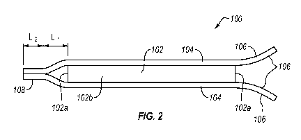
[0010] Figure 1 is a top view of an example embodiment of a filter media
laminate;
[0011] Figure 2 is a lengthwise side/section view of the example filter
media laminate of
Figure 1;
[0012] Figure 2a discloses an alternative to the configuration of Figure 2;
[0013] Figure 3 is an end view of the example filter media laminate of
Figure 1;
[0014] Figure 4 is widthwise section view of the example filter media
laminate of Figure
1;
[0015] Figure 5 is a top view of another example embodiment of a filter
media laminate;
[0016] Figure 6 is an end/side view of the example filter media laminate of
Figure 5;
[0017] Figure 7 is a lengthwise section view of the example filter media
laminate of
Figure 5;
[0018] Figure 8 is a top view disclosing attachment of a laminate wing to a
filter core;
[0019] Figure 9 is a side view disclosing attachment of an outer non-woven
layer to an
inner non-woven layer; and
[0020] Figure 10 is a flow diagram disclosing aspects of an example
production process.
4
CA 03000309 2018-03-28
WO 2017/055914 PCT/1B2016/001472
DETAILED DESCRIPTION OF SOME EXAMPLE EMBODIMENTS
[0021] Reference will now be made in detail to aspects of various
embodiments of the
present disclosure, examples of which are illustrated in the accompanying
drawings. While
described in conjunction with these embodiments, it will be understood that
they are not
intended to limit the disclosure to these embodiments.
[0022] In general, embodiments of the invention can be employed in
connection with
devices, such as fluid containers, where there is a need to filter fluid
before the fluid is
dispensed from the container. In one particular example, embodiments of the
invention can
be used in conjunction with a water pitcher, although the scope of the
invention is not limited
to this example environment and extends, more generally, to any environment
where such
embodiments can be usefully employed. For example, embodiments of the
invention can be
employed with any water, or other fluid, container, examples of which include,
but are not
limited to, water bottles, carafes, and jugs.
[0023] A. Example Filter Media Laminate Configuration and Materials
[0024] Directing attention now to Figures 1-4, details are provided
concerning a filter
media laminate, one example of which is denoted generally at 100. As
indicated, view A-A
is a lengthwise side view of the filter media laminate 100 and corresponds to
Figure 2, view
B-B is an end view of the filter media laminate 100 and corresponds to Figure
3, and view C-
C is a widthwise section view of the filter media laminate 100 and corresponds
to Figure 4.
[0025] In general, the filter media laminate 100 comprises multiple layers
that
collectively form a stack. In the illustrated embodiment, the filter media
laminate 100
includes one, or more, ACF layers 102 positioned between two layers 104. Where
multiple
ACF layers 102 are employed, the ACF layers 102 can be attached to each other
in one or
more locations, such as at one or more of the edges of the ACF layers 102 for
example. More
generally, the ACF layers 102 can be attached to each other in any way that
does not
CA 03000309 2018-03-28
WO 2017/055914 PCT/1B2016/001472
materially compromise the performance of the ACF layers 102, such as the flow
rate through
the ACF layers 102. Each of the layers 104 may comprise, or consist of, a
layer of non-
woven material. As such, some embodiments of the layers 104 may be referred to
herein as
'non-woven' layers. In an alternative embodiment, the filter media laminate
100 consists of
an ACF layer 102 disposed between a pair of non-woven layers 104, that is, in
this alternative
embodiment, the filter media laminate 100 consists of a total of three layers,
no more and no
less.
[0026] With continued reference to Figures 1-4, the ACF layer 102 may take
the form of
a non-granular, non-particulate, non-woven, activated carbon fiber (ACF)
material. One
example of a suitable activated carbon fibrous felt material is available from
Kuraray
Chemical Co., LTD of Osaka, Japan under the trade name KURACTIVE. Another
example
of suitable ACF is available from Jiangsu SuTong (JSST) Carbon Fiber Co., Ltd.
of China.
[0027] In at least some embodiments, the ACF layer 102 may have a thickness
in a range
from about 0.5 mm to about 2 mm (e.g., in a range of about 0.75 mm to about 1
mm).
However, a thickness less than about 0.5 mm (e.g., about 0.1, about 0.25,
etc.) or greater than
about 2 mm (e.g., about 2.5 mm, about 3 mm, about 4 mm, about 5 mm, about 10
mm, etc.) is
also contemplated. Indeed, any of the above numeric values of thickness in
units of
centimeters, inches, etc. can also be suitable in certain implementations.
[0028] The thickness of the ACF layer 102 can be selected based on a
variety of
considerations. For example, the thickness of the ACF layer 102 can be
determined at least
in part by a desired flow rate through the ACF layer 102. Thus, the thickness
of the ACF
layer 102 may be such as to permit a flow rate through the ACF layer 102 in a
range of about
0.5 gpm to about 1.5 gpm. In another example, the thickness of the ACF layer
102 may be
such as to permit a flow rate through the ACF layer 102 in a range of about
0.6 gpm to about
1.2 gpm. In a final example, the thickness of the ACF layer 102 may be such as
to permit a
6
CA 03000309 2018-03-28
WO 2017/055914 PCT/1B2016/001472
flow rate through the ACF layer 102 in a range of about 0.3 gpm to about 1.0
gpm. One,
some, or all, of the aforementioned flow rate ranges can be achieved when the
filter media
laminate 100 assumes a curved configuration such that water entering and/or
leaving the filter
media laminate 100 passes through a curved surface of the filter media
laminate 100.
[0029] Turning now to the layers 104, one or both of the layers 104 may
comprise, or
consist of, a non-woven material, such as a layer of polyester for example,
having first and
second opposing surfaces. As well, one or both sides of the layer 104 include
an adhesive
106. The adhesive 106 can take any form, such as a coating or a layer, or can
be impregnated
into the polyester. In one particular embodiment, the adhesive 106 is a heat-
activated
adhesive, such as a polyethylene (PE) binder that is dispersed evenly on the
surfaces of the
polyester. The adhesive 106, in this example, has a higher melting point than
the melting
point of the polyester. As such, the adhesive 106 can be melted without
melting or otherwise
damaging the polyester material. In an alternative embodiment, the adhesive
106 may be a
pressure-activated adhesive.
[0030] It should be noted that it is important, when selecting material for
the layers 104,
that the material not compromise the performance and effectiveness of the ACF
layer 102.
Thus, the layers 104 should each consist of, or substantially comprise, a
material whose
permeability is about the same as, or higher than, a permeability of the ACF
layer 102. Put
another way, the porosity of each of the layers 104 should be about the same
as, or higher
than, the porosity of the ACF layer 102, and the density of each of the layers
104 should be
about the same as, or lower than, the density of the ACF layer 102.
[0031] With continued reference to Figures 1-4, further details are
provided concerning
the example filter media laminate 100. As shown in Figures 1 and 2 for
example, the length
of the ACF layer 102 may be relatively shorter than a length of the layers
104. As a result of
this configuration, a widthwise extending wing 108 can be formed at each end
of the filter
7
CA 03000309 2018-03-28
WO 2017/055914 PCT/1B2016/001472
media laminate 100. As best shown in Figure 2, each wing 108 is formed by
attaching the
layers 104 to each other at a location beyond the widthwise edge 102a of the
ACF layer 102.
In the particular example of Figure 2, the wing 108 is formed by coextensive
portions of the
upper and lower layers 104.
[0032] In other embodiments however, and with reference to Figure 2 as well
as Figure
2a, particularly the left-hand side of Figure 2a, the wings 108 can
alternatively be configured
using only one of the upper or lower layers 104. For example, one or both of
the wings 108
can be configured such that, for example, the left-hand wing 108 is formed by
a piece of one
of the layers 104 that extends past the edge of the other layer 104. The
extending portion can
be part of the upper layer 104 or the lower layer 104. In one particular
embodiment, and with
continued reference to Figures 2 and 2a, the left-hand wing 108 can be
configured such that
the left-hand wing 108 is formed by a portion of the lower layer 104 that
extends beyond the
edge of the upper layer 104 instead of terminating at the same location as the
upper layer 104
as shown in Figure 2. Similarly, the right-hand wing (not shown) is formed by
a portion of
the upper layer 104 that extends beyond the edge of the lower layer 104. These
arrangements
can also be reversed.
[0033] As a result of the attachment of the two layers 104 to each other,
the widthwise
edges 102a of the ACF layer 102 are substantially, or completely, enclosed by
the layers 104.
In the example of Figures 1-4, the lengthwise edges 102b of the ACF layer 102
are not
enclosed by the layers 104. In other embodiments however, such as the
embodiment of
Figures 5-7 for example, all of the edges of the ACF layer 102 may be enclosed
by the layers
104. In any case, because the layers 104 may include an adhesive, such as the
adhesive 106
discussed elsewhere herein, the layers 104 can be bonded to each other, such
as by the
application of heat for example. Further details concerning some example
production
processes are set forth elsewhere herein.
8
CA 03000309 2018-03-28
WO 2017/055914 PCT/1B2016/001472
[0034] Depending upon the use(s) to which the filter media laminate 100 is
to be put, it
may be useful to ensure that the wings 108 are of a particular length. As
shown in Figures 1
and 2, an overall length of the wings 108 may be defined by the sum of a first
length L1 and a
second length L2. The first length L1 may be sufficient to ensure that the end
102a of the
ACF layer 102 will be enclosed when the layers 104 are attached to each other
and, as such,
the first length L1 may be referred to herein as a sealing portion of a wing.
The second length
L2 may be sufficient to ensure that the size of the wing 108 is adequate to
enable the wing
108 to be attached to a structure, such as a filter core for example, and, as
such the second
length L2 may be referred to herein as an attachment portion of a wing.
Further details in this
regard are provided below in connection with the discussion of Figure 9. As
with the other
dimensions of the filter media laminate 100, the dimensions of the wings 108
can be selected
as necessary. The wings 108 may have the same dimensions as each other,
although that is
not necessarily required. As well, in one particular embodiment, both the
first length L1 and
the second length L2 are about 10 mm, although larger or smaller dimensions
could be used
and/or one of the lengths may be different from the other length.
[0035] With continuing reference to the size and configuration of the
example filter
media laminate 100, the dimensions of the filter media laminate 100 may, in
general, be
selected based upon the intended application or use of the filter media
laminate 100. Thus, in
one particular example, the ACF layer 102 may have a length of about 220 mm,
and an
overall width 'W' of about 85 mm, although larger, or smaller, lengths and
widths can
alternatively be used. Because the lengthwise edges 102b of the ACF layer 102
are not
enclosed by the layers 104 in this embodiment, the overall width of the ACF
layer 102 is the
same, or nearly the same, as the overall width of the filter media laminate.
In this particular
example, the two wings 108 may each have an overall length of about 20 mm,
such that the
overall length 1' of the filter media laminate 100 is about 260 mm. In some
embodiments at
9
CA 03000309 2018-03-28
WO 2017/055914 PCT/1B2016/001472
least, the overall width 'W' may correspond to a dimension of a structure such
as a filter core
while, in these embodiments, the overall length 1' of the filter media
laminate 100 may be
sufficient to enable the filter media laminate 100 to be wrapped two, or more,
times around a
structure such as a filter core.
[0036] The ACF layer 102 need not be rectangular in all embodiments. Thus,
in one
particular embodiment, the ACF layer 102 is generally square in shape.
Likewise, some
embodiments of the layers 104, and filter media laminate 100, may be generally
square.
More generally, the filter media laminate 100 and its components can be any
shape needed to
suit an intended application, where such shapes include, but are not limited
to, round, square,
rectangular, polygonal, elliptical, or any other shape.
[0037] With reference now to Figures 5-7, details are provided concerning
another
embodiment of a filter media laminate, denoted generally at 200. Except as
noted in the
following discussion, the filter media laminate 200 may be similar, or
identical, to the filter
media laminate 100. As indicated, view D-D is a widthwise end view of the
filter media
laminate 200 and corresponds to Figure 6 (which also indicates a lengthwise
side view of the
filter media laminate 200), view E-E is a lengthwise section view of the
filter media laminate
200 and corresponds to Figure 2, and view F-F is a widthwise section view of
the filter media
laminate 200 and corresponds to Figure 7.
[0038] Similar to the filter media laminate 100, the filter media laminate
200 may include
an ACF layer 202 disposed between first and second layers 204. As best shown
in Figure 5,
and in contrast with the embodiment of Figures 1-4, the ACF layer 202 and the
layers 204
may be configured and arranged such that the ACF layer 202 is completely
enclosed on all
sides by the layers 204. As such, the attachment of the layers 204 to each
other may result in
the definition of a wing 206 that extends about the entire perimeter of the
filter media
laminate 200.
CA 03000309 2018-03-28
WO 2017/055914 PCT/1B2016/001472
[0039] It will be apparent from this disclosure that the structure of the
various
embodiments of the filter media laminate may provide a number of benefits. For
example,
and with reference to the example of Figures 1-4, the layers 104 of the filter
media laminate
100 are relatively durable and thus provide a measure of protection to the ACF
layer 102
which may be relatively weak and brittle. The layers 104 also provide
structural integrity to
the filter media laminate 100. As well, the layers 104 can help to prevent
contamination of
the ACF layer 102 during manufacturing of a device that includes the filter
media laminate
100, such as the filter core discussed in connection with Figure 8 below.
Further, because the
permeability of the layers 104 is about the same as, or greater than, the
permeability of the
ACF layer 102, the layers 104 do not impair the filtering functionality or
capability of the
ACF layer 102.
[0040] Turning now to Figures 8 and 9, details are provided concerning some
example
arrangements involving the attachment of wings to various other elements. It
should be noted
that the example filter media laminate embodiments 300 and 400 respectively
disclosed in
Figures 8 and 9 may be similar, or identical, to any of the other disclosed
embodiments of a
filter media laminate. With reference first to the example of Figure 8, the
filter media
laminate 300 includes a wing 302 that is, or may be, attached to a hollow
filter core 350. In
more detail, and as noted elsewhere herein, the wing 302 may include adhesive,
such as a
heat-activated adhesive for example. Thus, the wing 302 can be securely
attached to the
hollow filter core 350 by applying heat to the wing 302 and melting the
adhesive which then
adheres the wing 302 to the hollow filter core 350. This method of attaching
the wing 302 to
the hollow filter core 350 may be referred to as heat staking. Because the ACF
layer (not
shown in Figure 8) is at least partly enclosed by the layers that form the
wing 302, the ACF
layer does not contact the hollow filter core 350. Moreover, because the wing
302 can be
11
CA 03000309 2018-03-28
WO 2017/055914 PCT/1B2016/001472
simply attached to the hollow filter core 350, the hollow filter core 350 does
not require any
special configuration or structure to engage the wing 302.
[0041] With reference now to the example of Figure 9, in the disclosed
embodiments, a
first portion of a filter media laminate can be attached to a second portion
of that filter media
laminate by heat staking, or other processes. Thus, in the illustrated
example, the filter media
laminate 400 includes a wing 402 that can be securely attached to another
portion of the filter
media laminate 400 by applying heat to the wing 402 and melting the adhesive
which then
adheres the wing 402 to the other portion of the filter media laminate 400.
Because, in some
embodiments at least, both the wing 402 and the other portion of the filter
media laminate
400 to which the wing 402 is attached include adhesive, the connection between
the wing 402
and that other portion may be particularly strong.
[0042] B. Aspects of Example Production Processes
[0043] With attention now to Figure 10, details are provided concerning
processes for
manufacturing a filter media laminate. One example of such a process is
denoted generally at
500. Initially, two layers, which may be non-woven layers, are cut 502 to a
size such that
when laminated together with an ACF layer, the two non-woven layers define a
pair of
wings. In at least some embodiments, the non-woven layers can be stacked
together and cut
to size at the same time. In other embodiments, the non-woven layers can be
separately cut.
In some embodiments, the same material is used for both of the non-woven
layers while, in
other embodiments, different respective materials are used for the non-woven
layers.
[0044] Next, the ACF layer is cut 504. In other embodiments, the ACF
layer(s) can be
cut before the non-woven layers, or at the same time as the non-woven layers.
In general, the
ACF layer can be cut to a size such that, when laminated together with the non-
woven layers,
the non-woven layers extend beyond at least two edges of the ACF layers, such
that at least
first and second wings are defined by the non-woven layers. Each of the wings
may include a
12
CA 03000309 2018-03-28
WO 2017/055914 PCT/1B2016/001472
sealing portion and an attachment portion. Thus, in at least some embodiments,
a length of
the ACF layer is shorter than the length of the two non-woven layers. In other
embodiments,
the length and the width of the ACF layer are shorter than, respectively, the
length and width
of the non-woven layers.
[0045] Once the non-woven layers and ACF layer have been cut, or otherwise
processed,
to the desired size, the non-woven layers and ACF layers are stacked 506
together to form the
structure of the filter media laminate. In particular, the ACF layer is placed
between the two
non-woven layers and positioned relative to the non-woven layers so that first
and second
wings of substantially the same size extend beyond respective first and second
edges of the
ACF layer. After the non-woven layers and the ACF layer have been positioned
relative to
each other, they can be held together, or otherwise restrained, in preparation
for the next stage
of the process 500.
[0046] After the non-woven layers and the ACF layer have been stacked and
positioned,
the non-woven layers are then attached 508 to each other and to the ACF layer.
In some
embodiments, the attachment process 508 is performed by heating the layer
stack so as to
activate an adhesive that is present on each side of the non-woven layers. In
this way, the
two layers are attached to each other at the wings, and the two layers are
also attached to the
ACF layer. The two non-woven layers may have adhesive distributed over a
substantial
portion, or all, of each of their two sides, that is, the side contacting the
ACF layer and the
side facing away from the ACF layer. Thus, when the stack is heated, most, or
all, of the
ACF layer becomes securely attached to both of the non-woven layers.
[0047] This secure attachment of the ACF layer to the non-woven layers
lends structural
integrity to the filter media laminate as a whole, and also prevents the ACF
layer from
folding or bunching between the two non-woven layers, thereby maintaining the
filtering
effectiveness of the ACF layer. As well, the secure attachment of the non-
woven layers to
13
CA 03000309 2018-03-28
WO 2017/055914 PCT/1B2016/001472
the ACF layer helps to ensure that the ACF layer will assume whatever shape
the filter media
laminate is configured to assume. For example, if the filter media laminate is
wrapped
around a cylindrical filter core, the ACF layer will assume the same wrapped
configuration.
[0048]
Finally, the completed filter media laminate can be attached 510 to a filter
structure, such as a filter core for example. Further details concerning such
a process, and
resulting filter configuration, are set forth in one or more of the 'Related
Applications'
referred to herein. In general however, in some embodiments, one of the wings
of the filter
media laminate can be heat staked to a filter core, and the free end of the
filter media
laminate wrapped around the filter core two or more times. Because the ACF
layer is
positioned between the two non-woven layers, there is little or no contact
between the ACF
layer and the filter core. When the filter media laminate has been completely
wrapped, the
wing on the free end can then be attached to the outer non-woven layer. In
those
embodiments where the wing and/or outer non-woven layer include an adhesive,
this
attachment process can be effected by heating the wing and the portion of the
outer non-
woven layer that is located proximate the wing.
[0049] The
present invention may be embodied in other specific forms without
departing from its spirit or essential characteristics. The described
embodiments are to be
considered in all respects only as illustrative and not restrictive. All
changes which come
within the meaning and range of equivalency of the claims are to be embraced
within their
scope.