Note: Descriptions are shown in the official language in which they were submitted.
CA 03000953 2018-04-04
WO 2017/072617 PCT/1B2016/056096
1
ELECTROMAGNETIC LINEAR MOTOR
The present invention relates to an electromagnetic linear motor. The motor
can be used to move the movable parts of various apparatuses, e.g. a
reciprocating linear compressor, a linear actuator, or a solenoid valve.
As an example application we refer to the field of compressors, in which
numerous types are known: piston-operated, screw-operated, lobed, with
propellers, centrifugal etc., for the most part moved by rotary motors.
There are other systems of linear compressors mostly applicable in
refrigeration systems. This sector may be improved by the introduction of a
suitable linear motor.
The main object of the present invention is to propose an electromagnetic
linear motor, in particular to produce linear compressors, actuators, and
solenoid
valves. Thanks to the linear motor one can e.g. make a linear reciprocating
compressor with double efficiency compared to the current reciprocating
compressors driven by rotary motors; in general the motor can be integrated
into
systems that require compression of a fluid, into compression systems, into
refrigerant systems, heat pumps or volume compressors for internal combustion
engines.
With the electromagnetic linear motor one is able to accomplish:
- a compact, modular, silent alternative linear compressor able, at the same
time, to produce high flow rates and prevalence, and/or hydraulic head;
- a linear reciprocating compressor that has reduced manufacturing
complexity and a relatively easy tune-up;
The same advantages are shared in the production of linear actuators
and/or solenoid valves, in particularly for distribution valves, with fully-
electronic
control, in reciprocating endothermic engines.
A linear motor and its advantageous variants are defined in the appended
claims, while features and advantages of the present invention are illustrated
by
the following description of some embodiments, illustrated with reference to
the
following figures:
- Figures la and lb show a sectional view of the linear motor configured to
drive a compressor, respectively in two different operating phases;
CA 03000953 2018-04-04
WO 2017/072617 PCT/1B2016/056096
2
- Figures 2a - 2h show schematic views in succession representative of a
complete working cycle of the linear motor with single permanent magnet;
- Figures 3a - 3h show schematic views in succession representative of a full
working cycle of the linear motor with a double permanent magnet;
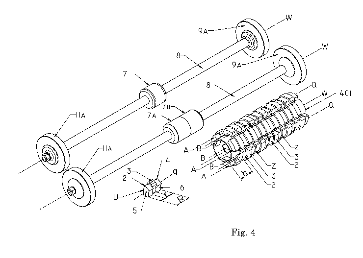
- Figure 4 shows a perspective view of some components of the linear motor
of Figure la and lb;
- Figures 5a - 5c show a front, above and perspective view, respectively, of a
compressor obtainable according to the present invention;
- Figure 5d shows a sectional view taken along the plane A-A of Figure 5b;
- Figures 6a - 6b show a sectional view of the linear motor configured as
actuator;
- Figures 7a - 7c show a side, front and perspective view of an actuator
driven by the linear motor;
- Figures 8a - 8c schematically show the operation of a distribution valve
driven by the linear motor with a permanent magnet;
- Figures 9a - 9c show a side, front and perspective view of an embodiment
of distribution valve driven by the linear motor;
- Figures 10a - 10c schematically show the operation of a distribution valve
driven by a linear motor with two permanent magnets;
- Figures 1 la - 11c show a side, front and perspective view of an
embodiment of a distribution valve operated by the linear motor.
In the following, identical numbers indicate identical or similar parts; and
the letters N and S indicate respectively North and South magnetic poles.
As a first application of the motor we refer to a compressor.
In Figure la there is shown in cross-section a compressor in a first phase of
an operation cycle. The compressor comprises the electromagnetic linear motor,
which comprises a stator 1 constituted by a plurality of electromagnets 2 (see
also Fig. 2).
Each electromagnet 2 comprises a core U on which are wound reels or
windings 3. In particular, the core U comprises a central linear segment 4,
with
an axis q, from the ends of which extend orthogonally to said axis q two polar
expansions 5 parallel to each other. The central linear segment and the two
polar
expansions 5 together form a ferromagnetic core in the shape of a "C" or a "U"
or
a "horseshoe". Preferably, the polar expansions 5 are recessed in the shape of
an
CA 03000953 2018-04-04
WO 2017/072617 PCT/1B2016/056096
3
arc 6, in the part distal to said axis q, with a radius slightly greater than
the
diameter of the permanent magnet 7 that they will skim. The longitudinal
dimensions of the ferromagnetic core are determined by the length R between
the
extreme edges of the polar expansions and by the distance r between the inner
edges of the polar expansions (Pig. 4).
The electromagnets 2 are stacked to constitute a cylindrical chamber 100
with a longitudinal axis W, so that the stator 1 has a generally tubular
shape.
Preferably the electromagnets 2 are applied on the side walls of a hollow
cylinder
401 (Pig. 4) and provided with through-holes in which the expansions 5 are
inserted.
Within the stator 1 is placed a cylindrical permanent magnetic component 7
which is mounted to slide along the axis W. The stator 1 surrounds the
permanent magnet 7 with the electromagnets 2, whose magnetic poles, i.e. the
polar expansions 5, are arranged radially and orthogonally with respect to
said
component 7 and consequently extend radially and orthogonally relative to the
axis W. The arcuate shape of the expansions 5 facilitates their symmetric
distribution about, and to skim, the permanent magnet 7 (Pig. 4).
The electromagnets 2 are linearly packed and stacked with their axes q
aligned to form columns A, B with axis Q, so that the expansions 5 of a column
A
are offset along the axis W compared to those of another column B. Each
electromagnet 2 is arranged linearly with another electromagnet 2, with
coincident axes q, so that the respective expansions 5, the poles, form along
the
columns a longitudinal sequence parallel to the axis W. The poles of the
permanent magnet 7 are oriented along the axis W.
In other words, there are columns of electromagnets 2 placed radially side by
side, arranged around the permanent magnet 7, and each column with axis Q
parallel to the axis W (axis of the stator 1, and thus longitudinal axis of
the
chamber 100). The electromagnets 2 when powered generate respective magnetic
poles that are placed in a row radial and parallel to the axis W and,
consequently,
to the permanent magnetic component 7 which they have to skim. The magnetic
field closes from an N pole to an S pole hitting the permanent magnetic
component 7 and the axis W.
In particular, the linear motor comprises at least a first plurality of
electromagnets 2 with related coils 3 with the cores' axes q linearly arranged
to
CA 03000953 2018-04-04
WO 2017/072617 PCT/1B2016/056096
4
form one of the columns A with axis Q. In the example shown (fig. 1, 4) there
are
indicated five electromagnets 2, and at least a second plurality of
electromagnets
2, with relative coils 3, with the core axes q placed lined up to form one of
the
columns B with axis Q. The bases of the columns A, B are offset from each
other
by a distance h in a direction parallel to the axis W.
The electromagnets 2 constituting the columns are linearly arranged with
coincident axes q to constitute an axis Q parallel to the axis W, with a
spacing Z
between the poles of each adjacent electromagnet. The spacing Z may vary
according to design and operational requirements.
The electromagnets 2 are preferably identical to each other, regardless of the
column they belong to.
The electromagnets 2 of a column A are arranged staggered along the axis W,
with respect to the electromagnets 2 of an adjacent column B, by a distance h.
The order of magnitude of the offset h between the columns A and B may vary
according to design and operational requirements.
In the example illustrated in Figure 4 there are visible a total of three
columns A and three columns B, five electromagnets 2 with axis Q, arranged
offset to each other by the distance h - in an alternating manner parallelly
to the
axis W.
The electromagnets 2 of a first column A are electrically powered and biased
in sequence, simultaneously or alternately to the electromagnets 2 of a second
column B staggered with respect to the first by the distance h.
In the following description, any spatial reference will refer to the spatial
arrangement as shown in the accompanying figures.
In Figure la is shown a first phase is shown of a complete compression cycle
of a fluid. By suitably biasing the electromagnets 2 of the various columns A
and
B, as will be better described below, one determines the displacement of the
permanent magnet 7 to the direction indicated by arrow D1 along the axis W.
The permanent magnet 7 is keyed on a stem 8 connected at the two ends
respectively to a first plunger 9a and a second plunger 1 la placed, in this
case,
symmetrically with respect to the permanent magnet 7; in the example each
plunger 9a, lla is placed at a respective end of the stem 8.
In particular the first plunger 9a is inserted airtightly in a first cylinder
9b,
and the second plunger ha is inserted watertightly in a second cylinder 11b.
CA 03000953 2018-04-04
WO 2017/072617 PCT/1B2016/056096
When the permanent magnet 7 moves upwards, moving in the direction of
arrow D1, a vacuum is created in the lower part 9c of the first cylinder 9b,
below
the first plunger 9a, leading to a depression and consequent suction of fluid
through a first suction opening 10a intercepted by a non-return suction valve.
At the same time, the fluid aspirated in the previous cycle and contained in
the top part 9d of the first cylinder 9b, above the first plunger 9a, is
compressed
and pushed through a first delivery opening 10b, intercepted by a non-return
delivery valve which communicates with a storage tank under pressure.
Symmetrically, the second plunger 11a, dragged by the displacement of the
permanent magnet 7, moves in the direction of arrow D1 causing a depression in
the bottom part 11c of the second cylinder 11b, under the second plunger 11a,
leading to a suction of fluid through a second suction opening 12a intercepted
by
a non-return-suction valve.
At the same time the fluid previously sucked and contained in the upper
part lid of the second cylinder 11b, above the second piston 11a, is
compressed
and pushed through a second delivery opening 12b, intercepted by a non-return
delivery valve that communicates with the storage tank under pressure.
In Figure lb a second phase of the complete cycle is shown, that of the
return. Here by appropriately biasing the electromagnets 2 of the various
columns A and B the downwards displacement of the permanent magnet 7 is
determined, to the direction indicated by the arrow D2.
The first plunger 94 by moving to the direction of arrow D2 determines a
depression in the top part 9d of the first cylinder 9b, resulting in a suction
of
fluid through a third suction opening 13a intercepted by a non-return suction
valve.
The previously-sucked fluid and contained in the lower part 9c of the first
cylinder 9b is compressed and pushed through a third discharge opening 13b
intercepted by a non-return delivery valve that communicates with the storage
tank under pressure.
Symmetrically, the second plunger 11a, dragged by the displacement of the
permanent magnet 7, moves to the arrow direction D2 causing a depression in
the top part lid of the second cylinder 11b, resulting in a suction of fluid
through a fourth suction opening 14a intercepted by a non-return suction
valve.
CA 03000953 2018-04-04
WO 2017/072617 PCT/1B2016/056096
6
At the same time the fluid previously sucked and contained in the lower part
11c of the second cylinder llb is compressed and pushed through a fourth non-
return delivery valve 14b that communicates with the storage tank under
pressure.
For each complete cycle, a displacement upwards in the direction D1 and a
displacement downwards in the direction D2, the compressor compresses a
volume of fluid equal to the volume of one of the two cylinders 9b, llb less
the
volume of a plunger 9a, lla multiplied by four:
Vcycle = (Vcylinder ¨ Vplunger) * 4, where V stands for volume (e.g. in m3).
This taking into account that the first and the second cylinder 9b, llb have
an identical volume, and that the first and the second plunger 9a, 1 la have
an
identical volume.
A small volume occupied by the stem 8 must be subtracted from Vcycle.
The capacity of the compressor, usually expressed in cubic meters per
minute, will be determined by Vcyde times the frequency of cycles per second
multiplied by sixty:
Capacity (m3/min) = (Vcycle * cycles/sec) * 60
A compressor as described and configured with two pistons is able to
compress a volume of fluid equal to that compressed by a reciprocating
compressor, moved by a rotary motor, with four pistons. The number of pistons
being equal and with the same size, it can compress a double quantity of
fluid.
In Figure 2a the start of the operating cycle of the electromagnetic linear
motor is schematically represented, which moves the compressor, in which two
columns A and B are highlighted, constituted by three electromagnets 2 and
relative coils 3 spaced by spacing Z. Such columns are alternately offset from
each other by the distance h.
For sake of simplicity, there are indicated columns A and B consisting of
three electromagnets 2.
Despite the electromagnets 2 being power-supplied individually, in order to
reduce the number of connections necessary for the motor's operation, the
coils 3
of the electromagnets 2 of each column are preferably connected in series with
each other. The power-supply of the individual coils takes place by applying
voltage to the terminals T of the coils 3. It can be observed that the series
CA 03000953 2018-04-04
WO 2017/072617 PCT/1B2016/056096
7
connection allows to power-supply three electromagnets with only four
terminals
instead of six.
In this example the movable magnetic component is represented by a single
cylindrical permanent magnet 7.
Figure 2a represents the beginning of the cycle in the direction D1, upwards
in the figure, that for sake of simplicity we call "forward".
The electromagnet Bl, of column B, is electrically powered with direct or
pulsed DC current, with a polarity such as to magnetize it with a magnetic
field
having the same polar orientation of the permanent magnet 7. To obtain this
object, for example an electronic control unit (not shown) is used connected
to the
windings 3. We will denote schematically the biasing mode with the symbols +
B1
- to indicate the positive pole applied to the lower terminal T of the coil
and the
negative pole to the upper terminal.
In this way, the S pole of the electromagnet B1 and the S pole of the
permanent magnet repel; similarly, the N pole of the electromagnet and the N
pole
of the permanent magnet repel. Instead the N poles of opposite sign of the
upper
pole of the electromagnet and the lower S pole of the permanent magnet 7
attract.
The permanent magnet 7 at the end of the previous cycle is moved upwards
relative to the electromagnet Bl. The permanent magnet 7 receives a double
thrust by the poles S-S and N-N and an attraction by the S-N poles upwards in
the direction Dl.
The permanent magnet 7 has preferably a length along the axis W equal to
the distance that there is between the opposite edges of the polar extensions
5
measured parallelly to the same axis W or distance R.
The thrust, and therefore the force to compress the fluid, is proportional to
the size of the electromagnets 3, the characteristics of the windings of the
coils,
the diameter of the permanent magnet 5, the applied voltage and resulting
adsorbed amperage.
After a time in the order of milliseconds, see the right side of Figure 2a,
completed the shift s 1, there is determined the new position of the permanent
magnet 7 resulting by the attraction between the S pole of the permanent
magnet
7 and the N pole of electromagnet Bl.
After this first period of time, see figure 2b, the electronic control unit,
set to
the linear motor's control, suspends power to the reel B1 and simultaneously
CA 03000953 2018-04-04
WO 2017/072617 PCT/1B2016/056096
8
powers the electromagnet Al biasing it + Al -, as in the previous phase, in
the
same the direction of the permanent magnet 7. The latter is now slightly
offset
from the electromagnet Al, and is further forced to move in the direction D1
coming in a new position shown at the right of Figure 2b in which the S pole
of
the permanent magnet 7, attracted by N pole of electromagnet Al, aligns with
the
latter having made a shift s2.
In figure 2c and 2d there are indicated the successive displacements s3 and
s4, and relative biasings, that occur with similar mode when polarizing
alternatively the electromagnets 2 of columns A and B.
In Figure 2d is represented the last displacement s4 which completes half of
the cycle.
Although the linear motor can work simply by setting a timer on and
alternating the power supply of the various electromagnets, it is preferable
to
insert two electromagnetic or photoelectric sensors 21 and 22 to signal when
the
permanent magnet 7 reaches the end of the stator 1 as shown in figure 2d and
2h.
Figure 2e shows the beginning of half return-cycle in the back direction D2,
opposite to the direction Dl. The coil A3 in column A is biased and, similarly
to
the forward cycle, the power supply of the electromagnets of the column A and
B
is alternated arriving at the end of the cycle, the latter being represented
in
Figure 2h.
With the sensor 22 the control unit detects the completion of the cycle and
starts a new cycle as in Figure 2a.
The operation described so far may take place by appropriately timing the
biasing sequence of the coils of the electromagnets 2 by the control unit. In
the
calibration phase of the system one must determine at what interval such
sequence should take place and what voltage to use according to the operating
pressure of the compressor.
The control unit preferably comprises means for varying the voltage and
frequency of the power-supply of the windings on the basis of variable
operating
needs. From Figure 3a to Figure 3h there is shown a variant of the linear
motor
with a stator identical to that reported in Figures 2a - 2h, but wherein the
movable permanent magnetic component is made no longer by one but by two
permanent magnets 7a, 7b. The magnets 7a, 7b are stacked and juxtaposed by
CA 03000953 2018-04-04
WO 2017/072617 PCT/1B2016/056096
9
the poles of equal polarity (in the illustrated example the poles N-N are
close
together).
The stator 1 is equal to the first variant with the columns A and B offset by
a
distance h from each other. In this case the mode changes with which the
biasing
of the electromagnets 3 takes place by means of the central unit since,
instead of
biasing only one magnet at a time, two adjacent magnets for each column are
biased at a time, that is, a pair of electromagnets at a time.
In figure 3a there is biased the pair of electromagnets B1 and B2, with mode
+ B1 - B2 +, so that the poles that are created match those of the two
permanent
magnets 7a, 7b. Even in this case, the permanent magnets, at the end of the
previous cycle, are slightly displaced compared to the electromagnets. This
determines between the various poles a quadruple thrust S-S-NN- NN S-S
between poles of the same sign, and a triple attraction S-S-NN NN between
poles
of opposite sign, for the permanent magnets to the direction Dl.
In the right part of Figure 3a, the two permanent magnets 7a, 7b have
reached the point of stability, in that the poles of opposite sign, S poles of
the
lower permanent magnet and N-N poles of the electromagnets B1 and B2 and N-N
poles of the permanent magnets and the electromagnet B2, attract and line up
having resulted in a shift sl.
Similarly to what has been already seen in Figures 2a- 2h, at this point,
figure 3b, the control unit suspends power-supply to the pair of
electromagnets
B1 and B2, and simultaneously biases the pair of electromagnets Al and A2,
with
mode + Al-A2 +, of the column A that cause the quadruple thrust and the triple
attraction of the permanent magnets thereby causing the shift s2.
In figure 3c, 3d are indicated the successive displacements s3 to s4, and
relative biasings, that occur with similar mode polarizing alternately upwards
a
pair of electromagnets of each of the columns A and B alternately.
Figure 3d shows the last shift s4 that completes half of the cycle detected by
sensor 21.
Similarly to what has been already seen in figures 2a-2h the return cycle
starts from Figure 3e and completes in Figure 3h detected by the sensor 22.
The latter double permanent magnet configuration shown in Figures 3a-3h
allows obtaining a greater thrust-force and thus higher heads than the
configuration with only one permanent magnet, shown in figures 2a-2h.
CA 03000953 2018-04-04
WO 2017/072617 PCT/1B2016/056096
According to the same principle, one may also use more than two stacked,
adjacent permanent magnets.
At top of figure 4 there is represented the upper movable part of the
electromagnetic linear motor, which drives the compressor, consisting of a
single
permanent magnet 7, the two pistons 9a, 11a and the stem 8 on which they are
fixed and, immediately below, the movable part in the case constituted by two
permanent magnets 7a and 7b with axis W.
In the lower part of Figure 4 on the left there is represented the single
electromagnet 2 with core U in the shape of a U or C, with relative coil 3,
the axis
q of the straight segment 4, the polar expansions 5 with an arc-recessed apex
6,
the overall distance R and the distance r between the poles. To the right, the
hollow cylinder or tube 401, with axis W, fixing six columns A and B with axis
Q,
each consisting of five electromagnets stacked with a spacing Z, staggered
from
each other in pairs by the distance h.
Note that, in the case of six columns, the corresponding columns are
arranged in a tripod fashion with respect to the axis W thereby privileging
axial
and non-eccentric thrusts during operation. In the case of four columns, the
homologous columns will be facing each other as will be seen later.
For a continuous and reliable operation the compressor may preferably
envisage the use of cooled oil for the simultaneous cooling of the
electromagnets 2
and the compression cylinders 9b, 11b, as well as the lubrication of the stem
8
and the bearing bushes 15 within which the stem 8 slides.
With reference to Figures 5a - Sc, there is shown respectively a front, above
and perspective view of one embodiment of compressor according to the present
invention.
In the abovementioned figures 5a - Sc there is shown an oil inlet 51 for the
cooling and lubricating and the relative outlets 52, the four non-return
delivery
valves 10b, 12b, 13b and 14b, the second non-return inlet valve 12a (the other
three not being visible in the figures), as well as an electrical connector 53
for the
power supply of the electromagnets 2.
In figure 5d there is shown a sectional view, made along the plane A of figure
3b, in which there are visible:
- the electromagnets 2 with the respective windings 3,
- the chamber 100,
CA 03000953 2018-04-04
WO 2017/072617 PCT/1B2016/056096
11
- a first free gap 54 for the cooling oil of the electromagnets 2, an oil
communication channel 55,
- a second free gap 56 for the cooling and lubrication oil of the bushings 15
(symmetrically arranged) and of the stem 8,
- a further oil communication channel 58 in communication with
- a third gap 59 for the cooling the compression cylinders 9b and 1 lb in
which the pistons 9a and 1 la slide.
In figure 6a and 6b an actuator is shown in two operation phases. The
actuator comprises the linear motor described above, wherein, though, the
compressor's pistons are replaced by an additional component 61 adapted for
moving objects or mechanical members.
With reference to Figures 7a - 7c, there is shown respectively a side, front
and perspective view of an embodiment of an actuator with piston rod 8 and
component 61.
With reference to Figures 8a - 8d, the operation of a distribution valve for
reciprocating engines driven by the linear motor is schematically shown, where
two columns A and two columns B are constituted of a single electromagnet Al
and Bl, and the movable part is represented by one permanent magnet 7.
In the example of Figure 8a the control unit supplies two electromagnets Al,
facing each other with respect to the axis W, by biasing them with the same
polarity of the permanent magnet 7 while it biases the electromagnets B1 with
polarity opposite to the permanent magnet 7, so that the N pole of the
permanent magnet 7 aligns S - N - S with both poles S of the electromagnets Al
and B 1. In the right part of figure 8a we see the new position of the
permanent
magnet determined by the displacement s 1 and the consequent opening of the
valve's head at position Hl.
At this point, Figure 8b, the control unit maintains the electromagnet Al
powered while inverting the biasing of the electromagnets B 1. This entails a
further downward displacement s 1 of the permanent magnet with the new
alignment S - N - S and the complete opening of the valve at position H2.
The closure occurs with a reversed biasing mode.
With this configuration, the biasing of the electromagnets differs from what
is described for the compressor and actuator, showing that the power supply
and
CA 03000953 2018-04-04
WO 2017/072617 PCT/1B2016/056096
12
biasing mode of the electromagnets is dependent upon the number of
electromagnets and the offset h between the columns.
In figures 9a - 9d there is represented an embodiment of a distribution valve
for reciprocating engines. In Figure 9a the complete valve 90 is visible with
the
stem 8 and the mushroom head 81; in figure 9b the side view of the stator 91
with two columns A and two columns B, each constituted of an electromagnet 2
with winding 3, offset by the distance h. Figure 9c is a perspective view of
the
same stator and figure 9d shows the movable part constituted of the permanent
magnet 7 with the stem 8 and the mushroom valve 81.
With reference to Figures 10a - 10d, the operation is schematically shown of
a distribution valve for reciprocating engines driven by the linear motor,
where
the two columns A and the two columns B, offset by the distance h, are
constituted respectively of two electromagnets which are spaced apart by the
spacing Z, and the movable part is represented by a double permanent magnet 7a
and 7b with mutually opposite poles S-S. In this case the offset distance h
between the columns A and B is less than that used in the motor equipping the
previously described compressor and actuator, while the spacing Z between the
poles of adjacent electromagnets is greater.
In the example of Figure 10a a control unit power-supplies two
electromagnets Al and A2 of the column A, opposite to each other relative to
the
axis W, by biasing them with mode + Al-, + A2- while the electromagnets of the
two columns B are not power-supplied. The N poles of the permanent magnet
attracted by the S poles of the electromagnets and the S poles attracted by
the N
poles determine the new position of the permanent magnet visible on the right
of
Figure 10a with consequent displacement sl and opening of the valve at
position
Hl.
At this point, Figure 10b, the control unit suspends the power supply of the
columns A and supplies the electromagnets of the column B, opposite one
another relative to the axis W, by biasing them in mode +B1-, +B2-. The poles
of
the permanent magnet align in the same way of figure 10a. This entails a
further
downward movement s2 and the complete opening of the valve head at position
H2.
CA 03000953 2018-04-04
WO 2017/072617 PCT/1B2016/056096
13
The closure, Figure 10c, occurs by biasing again +A- the electromagnets A
and subsequently +B- the electromagnets B of Figure 10d until the complete
closure of the valve.
Also in this case it is noted that the biasing mode of the electromagnets
depends on the length of the columns A and B, the spacing Z between the poles
of the electromagnets that constitute the columns, the offset h between
columns
A and B and the number and shape of the permanent magnetic component used.
In the specific case of Figure 10a the offset distance h between the columns
and
the spacing Z between the poles of the electromagnets are equal.
For the motor, in general:
- the number of columns of electromagnets and/or in a column may vary;
and/or
- preferably, to a column of electromagnets corresponds in the stator a
homologous column of electromagnets placed in a diametrically opposite
position
with respect to the axis W. If the columns are four: a column A is opposed to
a
column A and column B is opposed to a column B. If the columns are six, three
columns are to be placed in a tripod fashion each oriented towards the axis W
and the same applies for the columns B, and so for more higher numbers of
columns. This way the central permanent magnet receives thrusts or attractions
that compensate each other while not being subjected to eccentric but only
concentric forces; and/or
- with stators of appropriate size not only two columns A and B but more
columns, all mutually offset, may be provided;
- the longitudinal offset h, parallel to the axis W, between heterologous
columns may vary based on design and operational requirements; and/or
- the spacing Z between the poles of the electromagnets constituting the
columns may vary depending on design and operational requirements; and/or
- the central permanent magnetic component may be constituted of a single
permanent magnet or by two or more permanent magnets adjacent to one
another with poles of same sign; and/or
- the central permanent magnetic component may be made from some
permanent magnets adjacent to one another with poles of opposite sign spaced
from each other; and/or
- the two expansions 5 of an electromagnet are preferably identical; and/or
CA 03000953 2018-04-04
WO 2017/072617 PCT/1B2016/056096
14
- the radius of curvature 6 of the two expansions 5 is slightly greater than
the diameter of the permanent magnet; and/or
- the biasing of the electromagnets may depend on:
the shape of the core of the electromagnets, and in particular the distance r
between the expansions 5,
the spacing Z between the polar expansions of the electromagnets which
make up the columns;
the magnitude of the offset h between columns;
the length of the permanent magnet;
the fact that the permanent magnetic component is constituted of a single
permanent magnet or consists of several magnets stacked with opposed poles or
with alternating poles in such case spaced;
- application needs, and all the listed components may vary.