Note: Descriptions are shown in the official language in which they were submitted.
CA 03001468 2018-04-09
WO 2017/072479
PCT/GB2016/053180
1
WATER GAS SHIFT PROCESS
This invention relates to water-gas shift processes.
The water gas shift process is well established as a means to increase the
hydrogen content
and/or reduce the carbon monoxide content of synthesis gases produced by steam
reforming,
partial oxidation and gasification of hydrocarbon and carbonaceous feedstocks.
The reaction
may be depicted as follows.
H20 + CO H2 + CO2
The reaction is mildly exothermic and a favourable equilibrium is obtained at
low temperatures.
To achieve acceptable conversion for many uses however, the water-gas shift
process is
carried out in two or more stages using different catalysts. Thus iron-
containing catalysts have
found widespread use as so-called high-temperature-shift (HTS) catalysts in
conjunction with
medium temperature shift (MTS) and low temperature shift (LTS) catalysts,
which are typically
based on copper, depending on the process requirements. Typically, the HTS
catalyst is
provided as a fixed bed in a first shift vessel and the MTS or LTS catalysts
as fixed beds in a
second shift vessel downstream of the first shift vessel. Because of the
exothermic nature of
the water-gas shift reaction, some cooling is generally applied to the part-
shifted gas between
the first and second shift vessels.
The useful life of these catalysts is largely determined by poisoning by
sulphur and halogen
species carried forward in the feed. In particular copper-containing catalysts
are susceptible to
poisoning by chloride species, such as HCI, present in the feed gas.
The ability of the copper-containing catalyst to withstand the impact of
chloride poising can be
improved by the addition of appropriate levels of alkali compounds. However,
there is a
potential for soluble species to be washed out or redistributed within the
catalyst bed during
upset conditions that lead to condensation.
Attempts have been made to place dedicated, insoluble, guard materials at the
inlet of the LTS
bed to capture incoming chloride species. For example, US3922337 discloses a
process for
producing hydrogen comprising contacting carbon monoxide with steam over a
solid material
which is more basic than zinc oxide and then over a low temperature shift
catalyst. The guard
material in this case was an alkalised alumina, or preferably a low-
temperature shift catalyst
bed in two parts, the inlet part of which contains alkali above the limit
normally acceptable for
low-temperature shift catalysts.
CA 03001468 2018-04-09
WO 2017/072479
PCT/GB2016/053180
2
However, these solutions have not proven as effective under modern operating
conditions. In
particular, as operators seek to run the LTS catalysts at conditions close to
the dew point, there
is a need for a process that reduces the risk of soluble components being re-
deposited in the
copper containing catalysts.
Accordingly, the invention provides a process for increasing the hydrogen
content of a
synthesis gas mixture comprising hydrogen, carbon oxides and steam, comprising
the steps of:
(i) passing the synthesis gas mixture at an inlet temperature in the range
300-450 C over a
first water-gas shift catalyst disposed in a first shift vessel to form a
first shifted gas
mixture, and
(ii) passing the first shifted gas mixture at an inlet temperature in the
range 170-300 C over a
second water gas shift catalyst disposed in a second shift vessel to form a
second shifted
gas mixture,
wherein the second water-gas shift catalyst comprises copper and the first
shift vessel contains
a sorbent material for capturing halogen contaminants disposed downstream of
the first water
gas shift catalyst.
The invention departs from the normal practice in which chloride guard beds
are not placed in
the first shift vessel due to concerns that they would not be effective. The
invention
overcomes the problems of the prior art processes. In particular, the risk of
condensation and
resulting contamination of the second shift catalyst is avoided.
The synthesis gas in the present invention may be any synthesis gas comprising
hydrogen and
carbon oxides, for example one containing hydrogen, carbon monoxide and carbon
dioxide
formed by the catalytic steam reforming, autothermal reforming or secondary
reforming of
hydrocarbon feedstocks such as natural gas or naphtha, or by the gasification
of carbonaceous
or biomass feedstocks such as coal or biomass. Nitrogen may be present in the
synthesis gas
mixture. The carbon monoxide content of the synthesis gas fed to the first
water-gas shift
catalyst is suitably 5 to 30 mole% on a dry gas basis but more reactive
synthesis gases having
carbon monoxide contents up to about 70 mole A, on a dry-gas basis, may be
used. By "dry
gas basis" we mean the composition of the gas mixture disregarding the steam
content.
The synthesis gas is preferably provided by steam reforming a hydrocarbon
stream comprising
methane.
The synthesis gas may be cooled if necessary to the inlet temperature for the
first water gas
shift vessel. Any suitable heat exchanger may be used but typically cooling
may be performed
using a waste heat boiler, optionally followed by one or more heat exchangers
that may be
used to heat water or process gas streams.
CA 03001468 2018-04-09
WO 2017/072479
PCT/GB2016/053180
3
The synthesis gas requires sufficient steam to allow the water-gas shift
reaction to proceed.
Whereas synthesis gases derived from processes such as steam reforming may
contain
sufficient steam, reactive synthesis gases generally are deficient in steam
and steam must be
added. Where steam addition is required, the steam may be added by direct
injection or by
another means such as a saturator or steam stripper. The amount of steam
should desirably
be controlled such that the total steam: synthesis gas volume ratio in the
synthesis gas mixture
fed to the first water-gas shift catalyst is in the range 0.3:1 to 4:1,
preferably in the range 0.3:1
to 2.5:1.
The process is preferably operated at elevated pressure in the range 1-100 bar
abs, more
preferably 15-50 bar abs.
The synthesis gas mixture is passed at an inlet temperature in the range 300-
450 C over a first
water-gas shift catalyst disposed in a first shift vessel to form a first
shifted gas mixture. The
first water gas shift catalyst may therefore be a high temperature shift
catalyst. For high
temperature shift catalysts, the inlet temperature is preferably 300-380 C and
more preferably
310-350 C so that the performance of the catalyst over an extended period is
maximised. The
shift process in the first shift vessel is preferably operated adiabatically
without cooling of the
catalyst bed, although if desired some cooling may be applied for example by
passing cooling
water under pressure through tubes disposed in the catalyst bed. The exit
temperature from
the first shift vessel is preferably 500 C, more preferably 475 C to maximise
the life and
performance of the catalyst.
The first shifted gas mixture may be cooled if necessary to the inlet
temperature of the second
shift vessel. Cooling may be by means of any suitable heat exchanger. For
example, cooling
may be applied by raising steam or heating water or by interchange with a feed
gas to the shift
process or another gas stream, such as a hydrocarbon feed stream or a product
gas stream
from the shift process or a downstream process.
The first shifted gas mixture is passed at an inlet temperature in the range
170-300 C over a
second water gas shift catalyst disposed in a second shift vessel to form a
second shifted gas
mixture. The first water-gas shift catalyst and the second water-gas shift
catalyst are different.
In the present invention, the second water-gas shift catalyst comprises
copper, which in use is
in a reduced state.
The second water-gas shift catalyst may be a copper-containing low-temperature
shift catalyst.
The second water-gas shift catalyst may be operated adiabatically in a low
temperature shift
process or cooling may be applied in an isothermal shift process.
CA 03001468 2018-04-09
WO 2017/072479
PCT/GB2016/053180
4
In a low-temperature shift process, a gas containing carbon monoxide
(preferably 4% v/v on
a dry basis) and steam (at a steam to total dry gas molar ratio typically in
the range 0.1 to 1.5)
is fed at typically an inlet temperature in the range 170-300 C, preferably
170-250 C, most
preferably 170-200 C to the shift vessel and passed over the copper-containing
catalyst in an
adiabatic fixed bed having an outlet temperature typically in the range 200 to
360 C at a
pressure preferably in the range 15-50 bar abs. The outlet carbon monoxide
content in the
second shifted gas stream is typically in the range 0.1 to 1.0%, especially
under 0.5% v/v on a
dry basis.
In so-called isothermal shift, a copper-containing catalyst is used in contact
with heat exchange
surfaces. The coolant conveniently is water under such a pressure such that
partial, or
complete, boiling takes place. A suitable pressure is 15 to 50 bar abs and the
resulting steam
can be used, for example, to drive a turbine or to provide process steam for
shift, or for an
upstream stage in which the shift feed gas is generated. The water can be in
tubes surrounded
by catalyst or vice versa. The inlet temperature for the water-gas shift
catalyst may be in the
range 200-300 C and the exit temperature from the isothermal shift catalyst
may be higher or
lower than the inlet temperature as desired.
Any suitable water-gas shift catalysts that are suitably active at the inlet
temperatures of the
first and second water-gas shift vessels may be used.
The first water gas shift catalyst in the first shift vessel may be a high-
temperature shift catalyst
comprising one or more iron oxides stabilised with chromia and/or alumina and
which may
optionally contain zinc oxide and one or more copper compounds. Conventional
chromia-
promoted magnetite catalysts may be used. Iron oxide/chromia shift catalysts
are
conventionally made by precipitation of iron and chromium compounds (that
decompose to the
oxides upon heating) from a solution of iron and chromium salts by the
addition of a suitable
alkaline reactant, e.g. sodium hydroxide or carbonate. The resulting
precipitate is then
washed, dried, and calcined and tableted to form catalyst precursor pellets.
The precursor
preferably has an iron oxide content (expressed as Fe203) of 60 to 95% by
weight. Preferably
the iron to chromium atomic ratio in the precursor is in the range 6 to 20,
particularly 8 to 12.
The precursor may contain oxides of other metals, e.g. aluminium, manganese,
or, especially,
copper. Particularly preferred precursors have an iron to copper atomic ratio
of 10:1 to 100:1.
Prior to use for the shift reaction, the pellets are subjected to reduction
conditions wherein the
iron oxide is reduced to magnetite (Fe304) and any chromium trioxide present
reduced to the
sesquioxide, chromia (Cr203). This reduction is often carried out in the
reactor wherein the shift
reaction is to be effected. The activity of the catalyst may be significantly
increased by
incorporating into the catalyst precursor particles of aspect ratio of at
least 2 and a maximum
dimension of at least 5000A (500nm), and preferably less than 15000A (1500nm)
into the
CA 03001468 2018-04-09
WO 2017/072479
PCT/GB2016/053180
catalyst precursor pellets. Preferably the chromia-promoted magnetite catalyst
comprises
acicular iron oxide particles. Such catalysts compositions are described in
U55656566.
Alternatively, it may be desirable to at least partially replace the chromia
in the iron-based first
water-gas shift catalyst with alumina or another stabilising oxide. Zinc oxide
and copper may
5 desirably also be present. Such catalysts are described for example in
EP2237882.
Alternatively the first water-gas shift catalyst in the first shift vessel may
comprise a metal-
doped zinc oxide/alumina composition. For example, a suitable catalyst
contains oxides of zinc
and aluminium together with one or more promoters selected from Na, K, Rb, Cs,
Cu, Ti, Zr,
rare earth elements and mixtures thereof. Such catalysts are described for
example in
EP2924002.
The water gas shift catalyst in the second shift vessel may be any copper-
based water-gas shift
catalyst, but is preferably a catalyst comprising copper and zinc oxide. When
the shift catalyst
contains copper and zinc oxide, its proportions need not be changed from those
which have
been previously proposed or used, for example containing up to about 70% of
copper by metal
atoms of the total copper and zinc, especially 10-50% copper. Usually copper
is in excess of
zinc, especially up to a ratio of about 6: 1 by atoms, and commonly about 1.5
to 2.5. Suitable
shift catalysts and low temperature processes using them are described in UK
Patent 1131631.
Preferred second water-gas shift catalysts comprise copper, zinc oxide and
alumina.
Preparation methods for such catalysts are described, for example, in
EP2049249,
EP2599541, EP1487578, EP2240273 and EP2442904. As with the iron-containing
high
temperature shift catalysts, the copper-based water gas shift catalyst is
typically provided in
oxidic form and prior to use the copper oxide is reduced using a reducing gas
to copper metal.
This reduction is often carried out in the reactor wherein the shift reaction
is to be effected.
Preferably the first water-gas shift catalyst in the first shift vessel is a
high temperature shift
catalyst, more preferably an iron-containing high temperature shift catalyst.
Suitable high-
temperature water gas shift catalysts include KatalcoTM 71-5 and KatalcoTM 71-
6 available from
Johnson Matthey PLC.
Preferably the second water-gas shift catalyst in the second shift vessel is a
copper-containing
low-temperature shift catalyst. Suitable copper-containing low-temperature
water gas shift
catalysts include KatalcoTM 83-3 and KatalcoTM 83-3X available from Johnson
Matthey PLC.
Preferably, the water gas shift process is performed adiabatically in the
first and second shift
vessels.
CA 03001468 2018-04-09
WO 2017/072479
PCT/GB2016/053180
6
In the present invention the first shift vessel contains a sorbent material
for capturing halogen
contaminants disposed downstream of the first water gas shift catalyst. By the
term "sorbent"
we include adsorbent and absorbent.
The sorbent material may be as described in the aforesaid US3922337. Thus the
sorbent
material may be any solid material which is more basic than zinc oxide. The
solid material
more basic than zinc oxide conveniently can be a basic compound of any element
of Group IA
or Group IIA of the Periodic Table (other than beryllium) or of any other
element, such as
manganese, having a compound which is basic enough. Preferably the compound
should be
an oxide, hydroxide or a carbonate, so as not to introduce interfering by-
products into the
reaction system. Since the quantity of halogen present and the quantity needed
to poison the
catalyst are extremely small it is often sufficient to use an alkali metal or
alkaline earth metal
compound or adsorption complex of an inorganic polymer such as a clay, or even
an ion
exchange resin. Which basic compound is used depends on how the solid basic
material is
brought into contact with the gas containing carbon monoxide and steam. The
basic material is
very conveniently used as a composition in which it is supported on a carrier
material. The
carrier material preferably has a moderate specific surface (that is, 5-200 m2
/g). Thus, the
sorbent material preferably comprises at least one of sodium oxide, sodium
carbonate,
potassium oxide or potassium carbonate supported on a carrier material, such
as an alumina,
silica, titania, zirconia, ceria, magnesia or zinc oxide, or a mixture
thereof, or a refractory
cement such as a calcium aluminate or a magnesium aluminate. The alkali
concentration is
preferably in the range 0.1 to 10% by weight, more preferably 0.5 to 5% by
weight, calculated
as sodium oxide or potassium oxide.
A preferred sorbent material is an alkalised refractory cement material, such
as a sodium
oxide-containing or potassium oxide-containing calcium aluminate.
Alternatively, a sodium
oxide-containing or potassium oxide-containing alumina, such as alpha-alumina,
may be used.
Potassium-containing sorbent materials are preferred. The amount of potassium,
expressed as
K20, is suitably 0.5 to 5% wt.
Without wishing to be bound by theory it is believed that the alkali reacts
with the chloride
contaminants to form the alkali metal chloride. This has been found
surprisingly to be effective
at the exit conditions from the bed of first water-gas shift catalyst.
The sorbent material should be effective for capturing halogen, in particular
the chloride
contaminants present in first shifted gas mixture, such as HCI. Preferably the
chloride content
of the first shifted gas mixture is reduced from an amount in the range 1-100
ppbv to an amount
0.5ppbv.
CA 03001468 2018-04-09
WO 2017/072479
PCT/GB2016/053180
7
The presence of the sorbent material in the first shift vessel downstream of
the first shift
catalyst reduces the halogen contaminants in the feed to the copper-containing
second water-
gas shift catalyst thereby extending its life. The location of the sorbent
material in the hotter
first shift vessel reduces the risk of condensation on the sorbent material
and therefore reduces
the risk of contamination of the second water-gas shift catalyst by soluble
components therein.
Typically, the first shift vessel comprises a cylindrical shell with domed
ends. The vessel is
usually installed with the axis of the cylinder aligned vertically. An inlet
is placed at or near the
top of the vessel and an outlet at or near the bottom of the vessel, such that
the flow through
the vessel is downwards. In one arrangement, a perforate gas collector is
disposed around the
outlet to prevent leakage of the catalyst or bed support material through the
outlet. The gas
collector may be formed from a perforate plate, mesh or screen. Such gas
collectors may be
cylindrical or frusto-conical in shape. In another arrangement, the catalyst
bed is supported on
a perforate grid or screen that extends across the inside of the vessel
creating a void in the
domed end above the outlet.
In the present invention, the sorbent material is preferably disposed
immediately downstream
of the first water gas shift catalyst. A perforate mesh or screen may be
provided to separate
the first water-gas shift catalyst from the sorbent material to simplify
unloading. The support
material may be particulate or may comprise a sorbent material coated onto the
surface of a
ceramic or metal structure, such as a honeycomb. Preferably the sorbent
material is
particulate to simplify loading and unloading. Thus the sorbent material may
be a granulated,
pelleted or extruded material. Preferably, the sorbent material is a pelleted
or extruded
material.
In a preferred arrangement, with flow of the first shifted gas stream
downwards though the first
shift vessel, the first shift vessel preferably contains a fixed bed of a
particulate shift catalyst
physically supported on, i.e. on top of, a bed of sorbent material. The
sorbent material may
therefore be used as a bed support for the first water-gas shift catalyst. The
sorbent material
when used as a bed support may be used alone or may be used in combination
with one or
more conventional particulate ceramic bed support materials.
In one embodiment, first shift vessel comprises a bed of the first water-gas
shift catalyst
supported on a bed of sorbent material disposed around a gas collector, which
may be within a
domed end of the vessel.
In another embodiment, the first shift vessel comprises a bed of the first
water-gas-shift catalyst
supported on a bed of sorbent material, which in turn is supported on a mesh,
grid, or screen
extending across the inside of the first shift vessel.
CA 03001468 2018-04-09
WO 2017/072479
PCT/GB2016/053180
8
Preferably the bed of sorbent material is used in combination with an inert
ceramic bed support
material. The inert ceramic bed support material may be in the form of
spheres, rings or
irregular lumps. The ceramic bed support material is typically a low surface
area alpha alumina
material and is not an effective sorbent for halogen contaminants in the first
shifted gas
mixture. The inert ceramic bed support materials may include DYPOR 607,
KATALCOTm 92-1
and KATALCOTm 90-1 available in different sizes from Johnson Matthey PLC.
The first water-gas shift catalyst and the second water-gas shift catalyst are
preferably
particulate materials, such as cylindrical shapes, having a diameter or width
in the range 3-
10mm and an aspect ratio (i.e. length/diameter or width) in the range 0.5-2,
preferably 0.5-1.
In a preferred arrangement, the pressure drop through the sorbent material is
lower than the
pressure drop through the first water gas shift catalyst. The pressure drop
may be altered by
using particles of different size, structured catalysts, or by using designs
that provide a larger
voidage. Accordingly, a lower pressure drop may be achieved by using larger
particle sizes
and/or by providing the sorbent material in the form of a shaped particle
comprising two of
more flutes or channels and/or one or more through-holes. Thus the sorbent
material may
have a diameter or width in the range 5-200mm and be in the form of spheres,
rings, cylinders
or irregular lumps or honeycomb-like structures. Preferably the sorbent
material is provided as
a particulate or monolithic material. Particulate sorbent materials desirably
have diameters or
widths in the range 10-50mm an aspect ratio in the range 0.5-2.
In a preferred arrangement, the first shift vessel contains a particulate
first water-gas shift
catalyst and a particulate sorbent material having a larger particle size than
the first water-gas
shift catalyst and having two or more flutes or channels and/or one or more
through-holes.
Preferably the particulate sorbent material comprises 3-12 flutes and 1-10
through holes as this
offers stronger sorbent materials that are less likely to suffer from breakage
during use.
Especially preferred sorbent materials are in the form of a cylindrical 4-
hole, 4-fluted
quadralobe or a cylindrical 5-hole, 5-fluted pentalobe.
It has been found useful to provide the sorbent material in two or more
different forms to
enhance the flow of the first shifted gas through the sorbent material to the
outlet of the first
shift vessel. Thus the sorbent material may be provided in two or more zones,
preferably 2, 3
or 4 zones around the outlet, each zone having a different particle size
and/or voidage. A first
zone, adjacent the first water-gas shift catalyst, may have the same particle
size and/or
voidage or a larger particle size and/or voidage than the first water-gas
shift catalyst. A second
zone downstream of and adjacent the first zone may have a larger particle size
and/or voidage
than the first zone. If a third zone is provided downstream of and adjacent
the second zone,
this may have a larger particle size and/or voidage than the second zone.
Similarly, if a fourth
CA 03001468 2018-04-09
WO 2017/072479
PCT/GB2016/053180
9
or further zone is provided downstream of and adjacent the third zone, this
may have a larger
particle size and/or voidage than the third zone. The zones may be provided as
layers within
the first shift vessel. These layers may be supported on a grid, mesh or
screen or be disposed
around a gas collector.
In one arrangement the sorbent material is provided as fixed bed of particles
comprising one or
more horizontal layers above one or more annular layers disposed around a gas
collector
situated adjacent an outlet from the first shift vessel. The one or more
annular layers may
comprise either one or more inert ceramic bed support materials or a sorbent
material. The
annular layer may be divided into an inner annular layer adjacent the gas
collector and an outer
annular layer extending to the vessel wall. The inner annular layer may
comprise either an
inert ceramic bed support material or a sorbent material. In one embodiment,
the inner annular
layer is an empty space formed by perforate mesh or screen around the gas
collector. The
outer layer is preferably sorbent material. The particle size and/or voidage
of the sorbent
material and the inert ceramic bed support materials may be varied to enhance
the flow of the
first shifted gas to the gas collector and outlet from the first shift vessel.
The first shifted gas mixture, which is depleted in halogen contaminants by
the sorbent material
may be recovered from the first shift vessel and passed, with appropriate
temperature
adjustment if necessary to the second shift vessel. Temperature adjustment by
means of
cooling with water or suitable gas is preferred. In the first and second shift
vessels, carbon
monoxide in the gas mixture is converted over the water-gas shift catalysts to
carbon dioxide
with the formation of hydrogen.
The second shifted gas stream, which is enriched in hydrogen and depleted in
carbon
monoxide, may be subjected to one or more further shift stages, but this is
usually
unnecessary. Preferably the second shifted gas stream is used in conventional
downstream
processes. Hence, the shifted gas, without further shifting, may be cooled to
a temperature
below the dew point so that the steam condenses. The de-watered shifted gas
mixture may be
fed to methanol, dimethyl ether, Fischer-Tropsch wax, olefin and other
chemical syntheses
processes or may be subjected to a stage of CO2-removal to generate hydrogen
for ammonia
synthesis or the generation of electrical power as part of an IGCC process.
The Invention will now be further described by reference to the drawings in
which;
Figure 1 is a depiction of one process according to the invention; and
Figure 2 is a depiction of one arrangement of sorbent materials in a first
shift vessel.
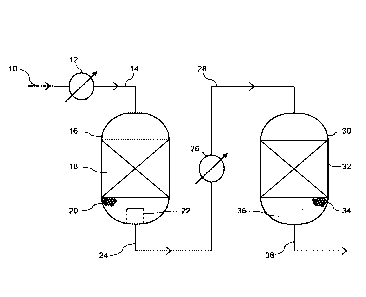
In Figure 1, a synthesis gas mixture 10 having a CO content in the range 5-30
mole% on a dry
gas basis and containing steam at a steam: synthesis gas volume ratio in the
range 1:1 to
CA 03001468 2018-04-09
WO 2017/072479
PCT/GB2016/053180
2.5:1, if fed to a heat exchanger 12 where the temperature is adjusted to a
temperature
between 300 and 450 C and passed via line 14 to an inlet at the top of a first
shift vessel 16
containing a first water gas shift catalyst 18. The first water-gas shift
catalyst 18 is in the form
of a fixed bed of a particulate high temperature shift catalyst. The
particulate high temperature
5 shift catalyst is suitably an iron-containing high temperature shift
catalyst in the form of
cylindrical pellets, such as KatalcoTM 71-5. The water-gas shift reaction
occurs as the
synthesis gas mixture is passed downwards through the bed 18 to convert a
portion of the CO
to CO2 and form hydrogen. The first shifted synthesis gas mixture passes from
the bed 18 to a
fixed bed of particulate sorbent material 20 disposed downstream of the first
water-gas shift
10 catalyst 18 and within the first shift vessel 16. The sorbent material
is suitably an alkalised
alumina in the form of 4-hole quadralobe pellets. The sorbent material is
effective at capturing
the halogen contaminants and reducing the chloride content of the first
shifted gas mixture. In
this embodiment, the sorbent material 20 supports the bed of first water-gas
shift catalyst 18
with the vessel 16. The sorbent material 20 may be divided into two or more
zones (not
shown), each having a different voidage and different pressure drop, that
enhance the flow of
the shifted gas through the bed 20. The sorbent material 20 is prevented from
leaking from the
vessel 16 by means of a gas collector 22 disposed about the outlet of the
vessel. The gas
collector 22 comprises a perforate member, such as a perforate screen or mesh
sized to
prevent the particles of sorbent material from passing through. The halogen-
depleted first
shifted gas mixture is recovered from the outlet of the first shift vessel 16
and fed via line 24 to
a heat exchanger 26 in which the temperature of the first shifted gas mixture
is adjusted to 170-
300 C. The temperature-adjusted, halogen depleted first shifted gas mixture is
passed from
the heat exchanger 26 via line 28 to an inlet at the top of a second shift
vessel 30 containing a
second water gas shift catalyst 32. The second water-gas shift catalyst 32 is
in the form of a
fixed bed of a particulate copper containing catalyst. The particulate copper-
containing catalyst
is suitably a copper-containing low temperature shift catalyst in the form of
cylindrical pellets,
such as KatalcoTM 83-3X. The water-gas shift reaction occurs as the first
shifted gas mixture is
passed downwards through the bed 32 to convert at least a portion of the
remaining CO to CO2
and form hydrogen. The second shifted gas mixture passes from the bed 32
though a
supporting bed of inert ceramic balls, pellets or lumps 34 disposed beneath
the second water-
gas shift catalyst 32 within the second shift vessel 30. The ceramic support
material may
suitably be high purity alumina spheres such as KatalcoTM 92-1, available from
Johnson
Matthey PLC. The ceramic support material may be divided into two or more
zones (not
shown), each having a different particle size and/or voidage, that enhance the
flow of the
shifted gas through the bed support material 34. The ceramic support material
34 is prevented
from leaking from the vessel 30 by means of a gas collector 36 disposed about
the outlet of the
vessel. The gas collector 36 may be the same type as that used in the first
shift vessel. The
second shifted gas 38, enriched in hydrogen and further depleted in carbon
monoxide, is
recovered from an outlet of the second shift vessel 30 and used in downstream
processes.
CA 03001468 2018-04-09
WO 2017/072479
PCT/GB2016/053180
11
In Figure 2 the bed of sorbent material 20 under the bed of first water-gas
shift catalyst 18 at
the bottom of the first shift vessel 16 is divided into four zones 40, 42, 44
and 46. The first and
second zones 40, 42 comprise horizontal cylindrical layers of particulate
sorbent materials.
The first zone 40 is disposed immediately beneath the first water gas shift
catalyst 18. The
second zone 42 is disposed immediately beneath the first zone 40. The third
and fourth zones
44, 46 are disposed as annular beds beneath the second zone 42. The third zone
44 is
disposed as an outer annular bed in contact with the vessel wall and the
fourth zone 46 as an
inner annular bed in contact with the gas collector 22. The first zone may be
separated from
the first water-gas shift catalyst 18 by a perforate mesh or screen (not
shown). If desired, the
first and second zones 40, 42 may be separated from each other by a perforate
mesh or
screen, but with a suitable grading of the particle size, this is not
necessary. The particle size
of the sorbent materials in the first and second zones may be the same, but in
a preferred
embodiment the particle size in the second zone 42 is larger than that of the
particles in the first
zone 40. The third zone 44 is separated from the fourth zone 46 by a perforate
mesh or screen
(not shown). Optionally, the second and third zones may also be separated by a
perforate
mesh or screen. The third zone 44 is filled with a particulate sorbent
material or particles of an
inert ceramic bed support material. The particles of sorbent material or inert
ceramic bed
support material may be the same size as the sorbent material in the second
zone 42 but in a
preferred embodiment the particle size in the third zone 44 is larger than
that of the particles in
the second zone 42. The fourth zone 46 may be filled with a particulate
sorbent material or
particles of an inert ceramic bed support material. The particles of sorbent
material or inert
ceramic bed support material may be the same size as the sorbent material in
the third zone 44
but in a preferred embodiment the particle size in the fourth zone 46 are
larger than that of the
particles in the third zone 44. In one embodiment, the fourth zone 46 is empty
such that there
is an empty space around the gas collector 22 defined by the perforate mesh or
screen, which
may be suitably reinforced. This arrangement offers a reduced overall pressure
drop though
the bed of sorbent material.
In use the first shifted gas mixture emerging from the first water gas shift
catalyst 18 passes to
the first zone 40 and then the second zone 42. The sorbent material in the
first and second
zones removes at least a portion of the halogen contaminants from the shifted
gas mixture at
the exit temperature of the first water-gas shift catalyst. The shifted gas
mixture then passes
through the third and fourth zones 44, 46 to the gas collector 22 and then to
the outlet of the
vessel 16.
The invention is further illustrated by reference to the following Examples.
CA 03001468 2018-04-09
WO 2017/072479 PCT/GB2016/053180
12
Example 1
A laboratory fixed bed reactor was charged with 50 ml of a potassium-doped
alumina sorbent
material containing 2% wt K20. A gas mixture mimicking a first shifted gas
mixture and
comprising (on a dry gas basis) 55%vol hydrogen, 25%vol nitrogen, 4%vol carbon
monoxide,
and 16%vol carbon monoxide and steam was passed through the sorbent material
for 25 days
at a flowrate of 13001/hr, a reactor temperature of 430 C, a pressure of 30
barg and a steam to
dry gas volume ratio of 0.5:1. The HCI concentration in the gas feed was
11.5ppbv. No
chloride was detected in the exit gas, using a Kitigawa gas test tube,
throughout the test period.
After the test was completed, the sorbent material was recovered and analysed
for Cl content.
The inlet portion contained 330ppm Cl and the exit portion 130ppm Cl. The
condensed water
was also collected and analysed for potassium content by ICP IES. No potassium
in the
condensate was observed. The results showed the effectiveness and stability of
the sorbent at
capturing the HCI under the exit conditions of a first shift vessel.
Example 2
Various arrangements according to Figure 2 were modelled to assess the overall
pressure drop
(dP) through the first shift vessel containing different particulate ceramic
support and sorbent
materials. The relevant support and sorbent data is shown in the following
tables:
Table 1 ¨ Ceramic support data
DYPOR 607 KATALCO 92-1 KATALCO 90-1
Code FB EC FD 92-1G 92-1K 90-1E 90-1H 90-1J
(Small) (Medium) (Large)
Diameter! 16.0 40.0 85.0 25.0 75.0 25-50 50-100 100-200
Width [mm]
Length 16.0 40.0 80.0
[mm]
No of through- 1 1 1
holes
hole Diameter 7.0 14.0 35.0
[mm]
Table 2 ¨ Sorbent material data
Sorbent material
Sorbent 1 Sorbent 2
Code
Diameter [mm] 13.0 16.0
Length [mm] 17.0 20.0
no. of holes 4 4
hole Diameter
[mm] 3.5 4.4
CA 03001468 2018-04-09
WO 2017/072479
PCT/GB2016/053180
13
DYPOR 607 is in the form of cylindrical rings, KATALCO 92-1 is in the form of
spheres and
Katalco 90-1 in the form of irregular lumps. Since the KATALCO 90-1 support
material is
made of irregular lumps, their size is given as a range (90-1E = 25-50 mm, 90-
1H = 50-100
mm, 90-1J = 100-200 mm). The sorbent materials, Sorbent 1 and Sorbent 2, were
in the form
of 4-holed, 4-fluted cylinders.
Shift Vessel (I)
A computer model of a first shift vessel (I) was based on high temperature
shift vessel
containing a particulate iron-based high temperature shift catalyst (Katalco
71-5/Katalco 71-6).
The conditions were as follows;
Flow 224.6 te/hr
Density 8.993 kg/m3
Viscosity 2.28x10⁻² cP
End ratio 4.426
h1 depth of zone 1(40) 76.2 mm
h2 depth of zone 2 (42) 25.4 mm
h3 depth of zone 3 (44) to top of collector (22) 100.0 mm
h4 height of collector (22) 528.6 mm
d1 diameter of collector (22) 1028.6 mm
d2 diameter of zone 4 (46) 1428.6 mm
d3 diameter of vessel (16) 4080.0 mm
Table 3 ¨ Pressure drop results of First Shift Vessel (I)
Comparative Example 2(a) Example 2(b) Example 2(c)
Example 2(d)
Sorbent in Sorbent in Sorbent in
Ceramic
zones 1 & 2 zones 1-3 zones 1-3
Sorbent in
Support in
and ceramic and ceramic and ceramic zones
1-4
Zones 1-4
support in support in support in
zones 3 & 4 zone 4 zone 4
Zone 1 90-1E Sorbent 1 Sorbent 1 Sorbent 1 Sorbent 1
Zone 2 90-1E Sorbent 1 Sorbent 1 Sorbent 1 Sorbent 1
Zone 3 90-1H 90-1H Sorbent 1 Sorbent 1 Sorbent 1
Zone 4 90-1J 90-1J 90-1J FD Sorbent 1
dP_support [bar] 0.027 0.029 0.050 0.037 0.167
dP_bed [bar] 0.181 0.181 0.181 0.181 0.181
dP_tot [bar] 0.208 0.210 0.231 0.218 0.348
dP_support [%] 13% 14% 22% 17% 48%
CA 03001468 2018-04-09
WO 2017/072479
PCT/GB2016/053180
14
In the comparative configuration, the support material has a pressured drop of
0.027 bar,
contributing 13% of the total pressured drop (catalyst bed + support).
If zones 1 and 2 are replaced by the chloride guard Sorbent 1 (Examples 2(a)),
the pressure
drop increases by a negligible amount (0.027 to 0.029 bar), and its
contribution to the total
pressure drop goes from 13% to 14%.
The amount of material that can be placed in zones 1 and 2 is limited;
therefore Example 2(b)
considers filling zone 3 as well with the chloride guard Sorbent 1. In this
case the support
pressure drop increases to 0.050 bar (22% of total), which is still deemed
acceptable.
When the material currently inside zone 4 is replaced by DYPOR 607 FD (Example
2(c)), then
the pressure drop is improved at 0.37 bar (17% of total).
Example 2(d) illustrates what would happen if the bottom of the first shift
vessel was filled with
the chloride guard Sorbent 1. In this case the pressure drop in the support
would be higher
than the other examples.
This example demonstrates that zones 1 and 2 may readily be filled with the
chloride guard,
and in case these zones are not large enough, a large additional volume of
zone 3 can be filled
with the chloride guard in the curved vessel bottom. In this case it is
preferred that the zone 4
material contains a ceramic support material of large particle size.
Shift Vessel (II)
A model of another first shift vessel (II) was based on high temperature shift
vessel containing
a particulate iron based high temperature shift catalyst (Katalco 71-5/Katalco
71-6). The
conditions were as follows;
Flow 213.7 te/hr
Density 8.731 kg/m3
Viscosity 2.25x10⁻² cP
End ratio 3.52
h1 depth of zone 1(40) 214.9 mm
h2 depth of zone 2 (42) 190.8 mm
h3 depth of zone 3 (44) to top of collector (22) 251.5 mm
h4 height of collector (22) 215.9 mm
d1 diameter of collector (22) 939.8 mm
d2 diameter of zone 4 (46) 1778.0 mm
CA 03001468 2018-04-09
WO 2017/072479
PCT/GB2016/053180
d3 diameter of vessel (16) 3886.2 mm
Table 4 ¨ Pressure drop results of First Shift Vessel (II)
Comparative Comparative Example Example Example Example
(2e) 2(f) 2(g) 2(h)
Ceramic Ceramic Sorbent in Sorbent in Sorbent in
Support in Support in Zones 1 & Sorbent in zones 1-4
zones 1-3;
Zones 1-4 Zones 1-4 2; ceramic Zones 1 & ceramic
support in 2; ceramic
support in
zones 3 & support in zone 4
4 zones 3 &
4
Zone 1 FB 92-1G Sorbent 1 Sorbent 1
Sorbent 1 Sorbent 1
Zone 2 EC 92-1G Sorbent 2 Sorbent 2 Sorbent 1
Sorbent 1
Zone 3 FD 92-1K EC FD Sorbent 1
Sorbent 1
Zone 4 FD 92-1K EC FD Sorbent 1 FD
dP_support [bar] 0.031 0.161 0.105 0.038 0.605 0.062
dP_bed [bar] 0.192 0.192 0.192 0.192 0.192 0.192
dP_tot [bar] 0.223 0.353 0.298 0.230 0.797 0.254
dP_support [%] 14% 46% 35% 17% 76% 24%
5
The comparative examples feature just support systems, and it can be seen that
the graded
support system gives a lower pressure drop.
Example 2(e) replaces zones 1 and 2 with the Sorbent 1 and Sorbent 2 chloride
guards, and it
10 uses DYPOR 607 EC in the bottom of the converter. The pressure drop
has clearly increased
from the first comparative examples but it is still lower than the solution
with the second
comparative example.
If a mesh is placed between zones 2 and 3 (Example 2f), allowing the bottom of
the vessel to
15 be filled with larger material, then the pressure drop goes back to
a value just slightly higher
than the first comparative example.
Example 2(g), where Sorbent 1 is placed in all 4 zones, produces a higher
pressure drop than
the comparative examples.
If a mesh screen is fitted around the gas collector (22) to define a zone 4
(46) and zone 4 is
filled with very large material (Example 2(h)), then the pressure drop goes
back to acceptable
levels, the rest of the vessel bottom still being completely filled with
chloride guard.