Note: Descriptions are shown in the official language in which they were submitted.
CA 03001577 2018-04-10
WO 2017/091299
PCT/US2016/056836
Skull-Mounted Deep Brain Stimulator
FIELD OF THE INVENTION
[0001] The present application relates to an implantable pulse generator
(IPG), such as a
Deep Brain Stimulator (DBS).
BACKGROUND
[0002] Implantable stimulation devices deliver electrical stimuli to nerves
and tissues for the
therapy of various biological disorders, such as pacemakers to treat cardiac
arrhythmia,
defibrillators to treat cardiac fibrillation, cochlear stimulators to treat
deafness, retinal
stimulators to treat blindness, muscle stimulators to produce coordinated limb
movement,
spinal cord stimulators to treat chronic pain, cortical and Deep Brain
Stimulators (DBS) to
treat motor and psychological disorders, and other neural stimulators to treat
urinary
incontinence, sleep apnea, shoulder subluxation, etc. The description that
follows will
generally focus on the use of the invention within a Deep Brain Stimulation
(DBS) system.
However, the present invention may find applicability with any Implantable
Pulse Generator
(IPG) or in any IPG system.
[0003] As shown in Figure 1, a DBS system includes an Implantable Pulse
Generator (IPG)
10, which includes a biocompatible device case 12 comprising titanium for
example. The
case 12 typically holds circuitry and a battery (not shown), which battery may
be either
rechargeable or primary in nature. The IPG 10 is coupled to electrodes 16 via
one or more
electrode leads 18 (two of which are shown). The proximal ends of the leads 18
include
electrode terminals 20 that are coupled to the IPG 10 at one or more connector
blocks 22
fixed in a header 24, which can comprise an epoxy for example. Contacts in the
connector
blocks 22 make contact with the electrode terminals 20, and communicate with
the circuitry
inside the case 12 via feedthrough pins 26 passing through a hermetic
feedthrough 28 to
allow such circuitry to provide stimulation to or monitor the various
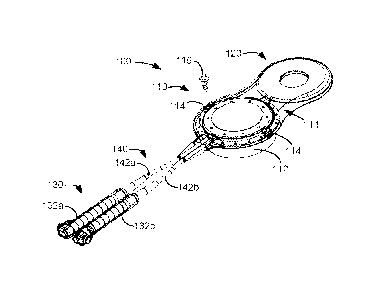
electrodes 16.
[0004] In a DBS application, as is useful in the treatment of Parkinson's
disease for example,
the IPG 10 is typically implanted under the patient's clavicle (collarbone),
and the leads 18
with electrodes 16 are implanted through holes drilled in the skull in the
left and right and
side of the patient's brain 32, as shown in Figure 2. Specifically, the
electrodes 16 may be
1
CA 03001577 2018-04-10
WO 2017/091299
PCT/US2016/056836
implanted in the subthalamic nucleus (STN), the pedunculopontine nucleus
(PPN), the Global
Pallidus Intema (GPI), and/or the Ventral Intermediate Nucleus (VIM). In this
regard, four
leads 18 may be necessary for full coverage, as discussed further in U.S.
Patent Application
Publication 2013/0184794. Thereafter, a tunnel is formed under the patient's
skin and fascia
(e.g., over the skull, behind the patient's ear, down the neck) to connect the
proximal ends of
the leads 18 to the IPG 10. As the distance from the skull holes to the IPG 10
is rather long,
extender leads 28 may be employed having receptacles 30 into which the
electrode terminals
20 of the leads 18 can be inserted. The extender leads 28 have their own
electrode terminals
(not shown) to allow connection to the connector blocks 22 in the IPG 10.
[0005] While DBS therapy employed in the manner shown can provide effective
neurostimulation therapy for a patient, the inventor sees room for
improvement. For one, the
extended distance between the IPG electronics (under the clavicle) and the
site of therapy
(the brain, near the top of the head) is inconvenient, as it requires a long
tunnel through the
patient. Further, if extender leads 28 are used, the possibility of a poor
electrical connection
between the electrode terminals 20 on the leads 18 and the receptacles 30 of
the extender
leads 28 can result in the disruption of neurostimulation therapy. Such
concerns have caused
the inventor to think of new solutions for implementing DBS therapy, and such
solutions are
disclosed herein.
SUMMARY OF THE INVENTIONS
[0006] A first example of an IPG comprises: a conductive housing comprising a
feedthrough
between a first cavity and a second cavity; a plurality of feedthrough pins
passing through the
feedthrough between the first cavity and the second cavity; a circuit board
comprising
electronic circuitry in the second cavity connected to each of the plurality
of feedthrough
pins; at least one electrode wire cable extending outwardly from the housing,
wherein each
electrode wire cable comprises a plurality of electrode wires coupled by
electrical
connections in the first cavity to some of the feedthrough pins; and a
connector block
connected to each at least one electrode wire cable, wherein each connector
block comprises
an opening configured to receive a lead for stimulating a patient's tissue,
wherein each of the
plurality of electrode wires in an electrode wire cable connected to a
connector block are
coupled to contacts in that connector block. The housing may comprise a
conductive top
cover and a conductive bottom cover, wherein the first cavity is defined
between the top
cover and the feedthrough, and wherein the second cavity is defined between
the bottom
2
CA 03001577 2018-04-10
WO 2017/091299
PCT/US2016/056836
cover and the feedthrough. The feedthrough, the top cover and the bottom cover
may lie in
planes that are parallel. The first and second cavities may be cylindrical.
The IPG may
further comprise an insulator between the electrical connections and the
feedthrough. The
circuit board may rest on a ledge of the housing inside the second cavity, and
an insulator
may be included between the circuit board and the ledge. The IPG may further
comprise a
charging coil antenna outside of the housing, wherein the charging coil
antenna is located in a
same plane as the housing, wherein the charging coil antenna is configured to
receive a
magnetic field to provide power to the electronic circuitry, and wherein the
charging coil
antenna is coupled by the electrical connections to other of the feedthrough
pins in the first
cavity. The IPG may also further comprise a battery, wherein power provided to
the
electronic circuitry comprises power provided to the recharge the battery. The
charging coil
antenna may encircle the housing, or may not overlap with the housing. The IPG
may further
comprise an overmold encompassing at least a part of the housing and the
charging coil
antenna. The IPG may also further comprise a data antenna outside of the
housing
configured to receive and/or transmit data to an external controller, wherein
the data antenna
is coupled by the electrical connections to other of the feedthrough pins in
the first cavity.
The housing may be circular, and the data antenna may be curved to follow at
least a portion
a periphery of the housing. The housing may comprise a cylindrical portion
configured to be
recessed in a hole in a patient's skull. The housing may further comprise at
least partial holes
configured to accept bone screws to allow the implantable pulse generator to
be affixed to a
skull of a patient when the cylindrical portion of the housing is recessed in
the hole in the
patient's skull. The at least one electrode wire cable may be flexible, and
there may be two
electrode wire cables and two connector blocks.
100071 A second example of an implantable pulse generator (IPG) comprises: a
conductive
housing; electronic circuitry within the housing; at least one electrode wire
cable extending
outwardly from the housing, wherein each electrode wire cable comprises a
plurality of
electrode wires connected to the electronic circuitry; and a connector block
connected to each
at least one electrode wire cable, wherein each connector block comprises an
opening
configured to receive a lead for stimulating a patient's tissue, wherein each
of the plurality of
electrode wires in an electrode wire cable connected to a connector block are
coupled to
contacts in that connector block. The IPG can further comprise a charging coil
antenna
outside of the housing, wherein the charging coil antenna is located in a same
plane as the
housing, wherein the charging coil antenna is configured to receive a magnetic
field to
3
84236691
provide power to the electronic circuitry. The IPG can further comprise a
battery, wherein
power provided to the electronic circuitry comprises power provided to the
recharge the
battery. The charging coil antenna may encircle the housing, or may not
overlap with the
housing. The IPG can further comprise an overmold encompassing at least a part
of the
housing and the charging coil antenna. The IPG can still further comprise a
data antenna
outside of the housing configured to receive and/or transmit data to an
external controller,
wherein the data antenna is coupled to the electronic circuitry. The housing
can be circular,
and the data antenna may be curved to follow at least a portion a periphery of
the housing.
The housing comprises a cylindrical portion configured to be recessed in a
hole in a patient's
skull, which housing may further comprise at least partial holes configured to
accept bone
screws to allow the IPG to be affixed to a skull of a patient when the
cylindrical portion of the
housing is recessed in the hole in the patient's skull. The at least one
electrode wire cable can
be flexible, and there can be two electrode wire cables and two connector
blocks.
[0007a] According to one aspect of the present invention, there is provided an
implantable
pulse generator, comprising: a conductive housing comprising a conductive top
cover, a
conductive bottom cover, and a feedthrough, wherein a first cavity is enclosed
between the
top cover and the feedthrough, and wherein a second cavity is enclosed between
the bottom
cover and the feedthrough, wherein the feedthrough, the top cover and the
bottom cover lie in
planes that are parallel; a plurality of feedthrough pins passing through the
feedthrough
between the first cavity and the second cavity; a circuit board comprising
pulse generator
circuitry in the second cavity connected to each of the plurality of
feedthrough pins; a battery
in the second cavity configured to provide power to the pulse generator
circuitry; at least one
electrode wire cable extending outwardly from the housing, wherein each
electrode wire cable
comprises a plurality of electrode wires coupled by electrical connections in
the first cavity to
some of the feedthrough pins; and wherein each at least one electrode wire
cable comprises a
connector block, wherein each connector block comprises an opening configured
to receive a
proximal end of a lead, the lead comprising a distal end including electrodes
for stimulating a
patient's tissue, wherein each of the plurality of electrode wires in an
electrode wire cable
connected to a connector block are coupled to contacts in that connector
block.
4
CA 3001577 2019-09-20
84236691
BRIEF DESCRIPTION OF THE DRAWINGS
[0008] Figure 1 shows an Implantable Pulse Generator such as a Deep Brain
Stimulator
(DBS), in accordance with the prior art.
[0009] Figure 2 shows the IPG of Figure 1 as implanted in a patient, in
accordance with the
prior art.
[0010] Figures 3A and 3B show an improved IPG as implanted in a DBS patient,
in
accordance with an example of the invention.
[0011] Figures 4A-4C show the improved IPG in isolation and in various view,
in accordance
with an example of the invention.
[0012] Figure 5 shows an exploded view of the components of the improved IPG,
in
accordance with an example of the invention.
[0013] Figures 6A-6D show various electrical connections with the improved
IPG, in
accordance with an example of the invention.
[0014] Figure 7A shows an underside of the housing of the improved IPG, while
Figures 7B
and 7C show cross sections through a feedthrough pin and a ground pin
respectively, in
accordance with an example of the invention.
[0015] Figure 8 shows components within a connection block section of the
improved IPG, in
accordance with an example of the invention.
4a
CA 3001577 2019-09-20
CA 03001577 2018-04-10
WO 2017/091299
PCT/US2016/056836
[0016] Figure 9 shows details of a Printed Circuit Board (PCB) within the IPG,
in
accordance with an example of the invention.
[0017] Figures 10A-10G show various steps in the construction of the improved
IPG, in
accordance with an example of the invention.
[0018] Figure 11 shows an alternative design for the improved IPG in which the
charging
coil encircles the housing, in accordance with an example of the invention.
DETAILED DESCRIPTION OF THE INVENTION
[0019] A first example of an improved DBS IPG device 100 is shown in Figure 3A
and 3B as
implanted in a patient, and in Figures 4A-4C in isolation and in perspective,
side, and top-
down views respectively. As shown in Figure 3A, viewing the top of a DBS
patient's head,
the IPG 100 is designed to lie generally flat against the patient's skull, and
preferably above
the patient's ear proximate to the temporal or parietal bones. Such placement
is preferable
because the skull in these locations is generally flat, therefore allowing the
IPG 100 to lay
relatively flat. However, because the IPG 100 is flexible at certain
locations, perfect flatness
of the skull is not required, as seen in the cross section of Figure 3B.
[0020] The IPG 100 is generally divided into four sections: an electronics
section 110, a
charging coil section 120, a connector block section 130, and an electrode
wire section 140.
Sections 130 and 140 are further comprised in this example of left and right
connector blocks
132a and 132b, each coupled to its own electrode wire cable 142a and 142b. In
this example,
each connector block 132/142 pair can couple to one of the eight-electrode
leads 18
illustrated earlier (Fig. 1). However, the number of connector block/electrode
wire cable
pairs is application specific, and can comprise one or more than two.
[0021] As shown in the cross section of Figure 3B, the IPG 100 is generally
flexible at the
connection 111 between the electronics section 110 and the charging coil
section 120, and
also at the electrode wire section 140, which as noted permits implantation of
the IPG 10
against the skull even if not perfectly flat. The charging coil section 120 is
also generally
flexible as it is largely comprised of silicone, as explained in detail later.
[0022] Electronics section 110 includes a conductive housing 112, which
includes the
electronics necessary for proper functioning of the IPG 100. As seen in the
various drawings,
housing 112 is generally cylindrical, and preferably comprises titanium. The
housing 112 is
designed to be mounted into a similarly shaped and sized hole 38 formed in the
patient's
skull 34, as shown in Figure 3B. The electronics section 110 further includes
one or more
CA 03001577 2018-04-10
WO 2017/091299
PCT/US2016/056836
screw holes 114 (e.g., two as shown) that proceed at least in part through the
housing 112,
and that receive bone screws 116 (Fig. 4A; only one screw shown) to allow the
IPG 100 to be
firmly secured to the skull 34 once the subassembly 112 is positioned in the
hole 38. In
Figure 3B, the hole 38 in the skull 34 for accepting the housing 112 proceeds
only partially
through the thickness of the skull 34, but in other examples may proceed all
the way through
to the dura (not shown) surrounding the brain 32. Notice from Figure 3B that
the IPG 100 is
fully implanted between the skull 34 and the skin/fascia 40 on top of the
skull.
[0023] Before securing of the IPG 100 to the skull 34, the implanting
physician will have
drilled one or more holes 36 in the skull 34 as shown in Figure 3A, and will
have inserted the
distal ends of leads 18 with the electrodes 16 into appropriate locations in
the brain 32, as
discussed earlier. The leads 18 once properly placed can be secured in holes
36 by the
physician using standard means, such as by cementing or plugging. Thereafter,
and once the
physician has verified the effectiveness of neurostimulation therapy using
standard DBS
surgical equipment (not shown), the IPG 100 can be secured to the skull 34 as
described.
Thereafter, proximal ends of the leads 18 with the electrode terminals 20
(Fig. 1) can be
inserted into the connector blocks 132a and 132b of the IPG's connector block
assembly 130.
In this example, both left and right leads 18 are used, and so the 1PG 100
includes two
connector blocks 132a and 132b in its assembly 130, although as noted earlier
this number is
variable. Leads 18 may be much shorter than those described in conjunction
with the prior
art, and extender leads (28, Fig. 2) are not required. Leads 18 may have some
slack along the
skull 34 as they proceed from the connector block assembly 130 to the holes
36.
[0024] IPG 100 is thus implanted much closer to the site of therapy¨a few
inches rather than
a foot or more¨and doesn't require a long tunnel through the patient. Further,
this shortened
distance renders communications 100 between the 'PG and the implanted
electrodes 16 less
complicated and more reliable. Further, the IPG 100 is small in size and
volume, as the
example dimensions depicted in Figures 4B and 4C show. Notice importantly that
the
electronics section 110 and charging coil section 120 only extended a small
distance (e.g., 3.3
mm) above the skull 34's surface when implanted. This low profile is
facilitated by the fact
that housing 112 of the electronics section 110 is implanted significantly
below the skull's
surface (e.g., 5.6 mm) in skull hole 38. The connector block assembly 130 also
has a relative
small profile (e.g., 3.8 mm), and thus the entire IPG 100 is easily
accommodated under the
patient's skin/fascia 40.
6
CA 03001577 2018-04-10
WO 2017/091299
PCT/US2016/056836
[0025] Figure 5 shows an exploded view of various components of the IPG 100,
which are
now identified and briefly explained. The function and purpose of these
components will
also be explained in conjunction with Figures 10A-10G, which illustrate
sequential steps in
the construction of the IPG 100.
[0026] Starting from the top of Figure 5 is a silicone overmold 150 which
serves to integrate
the electronics 110 and charging coil sections 120, and to provide soft
surfaces for portions of
the IPG 100 that might come into contact with a patient's tissue/fascia 40.
Screw holes 114
referred to earlier are seen in the overmold 150, as well as partially formed
in a lip 161 of the
housing 112. Alternatively, if lip 161 is larger or the bone screws 116 (Fig.
4A) smaller,
screw holes can be fully formed in the lip. Top cover 152, preferably
comprising titanium, is
eventually laser welded to the top of the housing 112, and includes two slots
153 to allow for
the passage of cabling to the electrode wire section 140 and to antennas 154
and 196, as
explained further below. Top cover 152 and a feedthrough 164 portion of the
housing 112
create a cavity 201 (Figs. 7B & 7C) in which electrical connections 180
(described below)
can be housed. The overmold 150 may further include a hole 159 to allow the
grounded
housing at top cover 152 to be tied to the patient's tissue 5.
[0027] Charging coil section 120 includes a charging coil antenna 154 within a
silicone
overmold 156, which is encompassed within overmold 150 during assembly. The
charging
coil antenna 154 is used to receive a magnetic field from a power source
external to the
patient (not shown), and is preferably used to charge the IPG 100's battery
170.
Alternatively, the IPG 100 may include a primary (non-rechargeable) battery
170, in which
case charging coil antenna 154 would be unnecessary. Battery 170 is preferably
coin shaped
as shown to better integrate with a circular printed circuit board 168 within
the housing 112.
However, IPG 100 may also lack a battery 170, and instead be designed to
continually
receive a magnetic field at charging coil antenna 154 from the external power
source to
provide the IPG the power it needs to function. In one example, battery 170 is
rechargeable,
with a capacity of 59 mAh.
[0028] Bi-directional data communications with the IPG 100 is facilitated by
the use of a
short-range RF antenna 196 that may include its own silicone overmold 198.
Data antenna
196 is preferably configured as a dipole antenna. The data antenna 196 is
preferably
positioned outside of the top cover 152 and housing 112, and is preferably
curved to follow at
least a portion of the circular contour of the periphery of the top cover 152.
Positioning the
data antenna 196 outside of conductive components such as the top cover 152
and the
7
CA 03001577 2018-04-10
WO 2017/091299
PCT/US2016/056836
housing 112 keeps such components from attenuating communications to and from
the
antenna 196. In one example, data antenna 196 can operate pursuant to a
Bluetooth
communications protocol, although other short-range RF protocols could be used
as well,
such as Zigbee, MICS, WiFi, etc. Alternatively, data communications can be
enabled via
magnetic fields received and transmitted from the charging coil antenna 154,
in which case
data antenna 196 may be unnecessary. Further details concerning external
devices with
which the IPG 100 can communicate, such as external chargers for providing
power (via a
magnetic field), patient external controllers, and clinician programmers, are
disclosed in U.S.
Patent Application Publication 2015/0360038.
[0029] Various electrical connections 180 are established inside the
electronics section 110,
including connections to the electrode wire section 140 and to the antennas
154 and 196.
Such signals ultimately attach to various feedthrough pins 188, as described
in further detail
with reference to Figures 6A-6D. A cable retainer clip 158 and an antennas
retainer clip 160,
both preferably formed of poly ether ether ketone (PEEK) and held within the
overmold 150,
secure connections to the electrode wire cables 142a and 142b and to the wires
associated
with antennas 154 and 196. As best shown in Figure 7C, a wedge at the bottom
of the clips
158 and 160 press fits into holes 177 formed on the lip 161 of the housing
112.
[0030] An insulator disk 162, also preferably formed of PEEK, intervenes
between the
electrical connections 180 and a feedthrough 164 formed in a top surface of
the housing 112.
The insulator disk 162 and the feedthrough 164 contain holes 163 and 165
respectively to
accommodate the passage of the feedthrough pins 188 therethrough, which pins
188 may
comprise titanium or copper for example. Holes 171 in the feedthrough 164
(e.g., two,
although more or less could be used) are configured to receive ground pins
190, as discussed
subsequently. The lip 161 of the housing 112 is encompassed within the
silicone overmold
150 during assembly, as best seen in Figures 7B and 7C. In the example shown
the
feedthrough 164 is integral with the housing 112 and the two are formed as one
piece.
However, this is not strictly necessary, and feedthrough 164 could for example
be welded
into place within the housing 112.
[0031] A printed circuit board (PCB) 168 is located below the feedthrough 164
inside of the
housing 112, and may carry battery 170 (if present) to power the IPG 100. The
top of the
PCB 168 can include an insulator ring 166, preferably formed of Kapton'TM,
with holes 167
and 173 allowing the feedthrough pins 188 and the ground pins 190 respectively
to pass
therethrough. The feedthrough pins 188 and the ground pins 190 connect to the
PCB 168 at
8
CA 03001577 2018-04-10
WO 2017/091299
PCT/US2016/056836
holes 169 and 175 respectively. A bottom cover 172 is laser-weldable to the
bottom of the
housing 112. This creates a cylindrical and hermetically sealed cavity 199
(Figs. 7B & 7C)
bounded by the parallel planes of the feedthrough 164 and the bottom cover 172
and the
circular sidewalls of the housing 112 in which the PCB 168 and battery 170 can
be safely
located. Note that housing 112 complete with its top cover 152 and bottom
cover 172 may
also be referred to as the -housing."
[0032] Figures 6A-6D show further details of the electrical connections 180
with the housing
112 removed for easier viewing. Electrode wires 182 from the electrode wire
cables 142a
and 142b (e.g., 8 wires in each) and antenna wires 181 from the data antenna
198 and the
charging coil antenna 154 (e.g., four wires, comprising the ends of the
antennas) are
connected to conductive terminals 184 formed in one or more substrates 200. As
shown in
Figure 6C, four substrates 200a-d are used in this example, with substrate
200a connecting to
the electrodes wires in electrode wire cable 142a; 200b connecting to the
electrode wires in
electrode wire cable 142b; 200c connecting to the ends of the charging coil
antenna 154; and
200d connecting to the data antenna 196.
[0033] As best seen in Figure 6D, the conductive terminals 184 may comprise
crimps (tie
bars) formed in conductive traces 206 in the substrates 200, which are crimped
(bent) over
the ends of the wires 181 and 182. Traces 206 in turn lead to contacts 186
that connect to the
feedthrough pins 188 that are eventually connected to the IPG's PCB 168. In
the example
shown, contacts 186 have a cross shape through which the ends of the
feedthrough pins 188
can be pressed to provide electrical and mechanical connections, although
these connections
may also later be soldered or laser welded. Still referring to Figure 6D, the
substrates 200a-d
can in one example comprise a metal lead frame that is dipped in silicone 205
to cover and
insulate the traces 206. Once the silicone 205 has cured, the silicone over
the crimps 184
may be excised, and holes 204 may then be formed (e.g., by laser ablation) to
disconnect the
various traces 204 in the lead frame from each other.
100341 Such means of establishing electrical connections 180 is not strictly
necessary, and
other variations can be made. For example, the substrates 200 may instead
comprise more
typical PCBs, and may be consolidated into a single substrate, although
forming them in
pieces (200a-d) facilitates IPG construction as shown later. Connection of the
wires 181, 182
and feedthroughs 188 to the substrates 200 can also be made in other ways, for
example, by
soldering.
9
CA 03001577 2018-04-10
WO 2017/091299
PCT/US2016/056836
[0035] Referring to Figures 6A and 6B, each feedthrough pin 188 ultimately
connects to its
corresponding node (at holes 169) on the PCB 168. Each feedthrough pin 188 is
further
surrounded by a ceramic bead 194 and a tube 192 preferably formed of
KryoflexTM ceramic.
The ceramic beads 194 and tubes 192 are located within holes 165 in the
feedthrough 164
(Fig. 5), although again the housing 112 and its feedthrough 164 is not shown
in Figures GA
or 6B for clarity. Once the ceramic beads 194 and tubes 192 are positioned
with the holes
165, and the feedthrough pins 188 are positioned therethrough, they are
sintered (melted) to
form a hermetic seal around the feedthrough pins 188. As well as providing a
good hermetic
seal for the feedthrough pins 188, the ceramic beads 194 and tubes 192 are
serve to insulate
the feedthrough pins 188 from the conductive body of the housing 112, which is
preferably
grounded by the ground pins 190, as explained further below.
[0036] Further details of how the feedthrough pins 188 and ground pins 190
pass through
feedthrough 164 and connect to the PCB 168 are shown in Figures 7A-7C. First,
note in
Figure 7A that the underside of the housing 112 includes a ledge 240. The top
surface of the
PCB 168 will rest against this ledge 240, with insulator disk 166 intervening
to prevent to
two from shorting, as shown in Figures 7B and 7C. Figures 7B and 7C
respectively show
cross sections through a feedthrough pin 188 and a ground pin 190. Notice in
Figure 7B how
the sintered ceramic bead 194 and tube 192 insulates the feedthrough pin 188
from shorting
to the conductive material of the housing 112. By contrast, no such insulation
occurs around
ground pin 190 as shown in Figure 7C, as it is desirable that the ground pin
190 pass ground
from the PCB 168 electronics 244 to the conductive material of the housing
112. Notice
further that the feedthrough pins 188 in Figure 7B are affixed to the PCB 168
in holes 169
and to appropriate corresponding PCB signals using conductive epoxy joints
242. Ground
pins 190 meet with a ground signal on the PCB at conductive retaining springs
179 at the
holes 175 in PCB 168. Ground pins are further connected to the housing 112 at
conductive
joints 246, as shown in Figure 7C. In an alternative embodiment, ground pins
190 may short
to the body of the housing 112 without penetrating fully through the body, and
thus holes 171
may not proceed through to the top cavity 201. This alternative may be
preferred so that
hermeticity of cavity 199 at the location of the ground pins 190 is not
compromised.
[0037] Figure 8 shows further details of the connector block section 130, with
some of the
components of connector block 132b removed for easier viewing. Covering the
components
of the connector blocks 132a and 132b is an overmold 210, which may be made of
silicone
for example. The proximal end of a lead 18 with its electrode terminals 20
(Fig. 1) is inserted
CA 03001577 2018-04-10
WO 2017/091299
PCT/US2016/056836
in an opening 213 of a lock 212 which can receive a set screw (not shown) at
perpendicular
port 214 to hold the lead 18 in place after it is fully inserted to an end
stop 222 in one of the
connector blocks. Each of the electrode terminals 20 when fully inserted will
meet with a
corresponding spring contact 220 formed of a deformable conductive material.
Each spring
contact 220 is encased in a conductive housing 218, and insulating seals 216
intervene
between adjacent conductive housings 218 to prevent them from shorting.
Although not
shown, electrode wires 182 from the electrode wire cables 142a and 142b
proceed between
the overmold 210 and the insulating seals 216, and each wire connects to a
corresponding
conductive housing 218/spring contact 220 at gaps 224 between the seals 216.
[0038] Figure 9 shows the underside of the PCB 168, and the electronics 244 it
carries. The
battery 170 is on the top side of the PCB 168 and thus not in view in Figure
9, but its solder
holes 234 can be seen. Note that the battery 170 and electronics 244 can be
reversed on the
PCB 168 with the former on the underside and the latter on the top side, or
the battery 170
and electronics 244 could be distributed on the PCB 168 in other fashions.
Further, note that
the IPG 100 need not include a battery in a continuous power example as
discussed earlier.
[0039] The IPG 100 can operate as described in various manners in U.S. Patent
Application
Publication 2013/0184794, and Figure 9 shows many of the components discussed
in that
publication, including: a microcontroller 250; an Application Specific
Integrated Circuit
(ASIC) 252, which among other details provides output currents to the
electrodes 16; DC-
blocking capacitors 254 through which output currents are routed on the way to
electrodes
16; etc. Also shown is a Bluetooth integrated circuit 256, which connects to
the data antenna
196 (Fig. 5) and provides modulation and demodulation circuitry to assist in
wireless data
transmission and reception. Other electronics 244 such as voltage regulators,
temperature
measuring circuitry, timing crystals, etc., are not shown for simplicity.
Notice that the
feedthrough pins 188 and their receiving holes 169 are shown along with the
conductive
epoxy 242 used to mechanically and electrically couple the feedthrough pins to
the PCB 168.
Likewise, ground pins 190 and their receiving holes 175 are shown along with
the retaining
springs 179 used to mechanically and electrically couple the ground pins to
the PCB 168.
[0040] With components of the IPG 100 explained, attention can be turned to
the manner in
which the IPG 100 is assembled with reference to Figures 10A-10G. Assembly
starts as
shown in Figure 10A by affixing the feedthrough pins 188 and ground pins 190
through the
feedthrough 164 of the housing 112. Ceramic beads 194 and tubes 192 are placed
in holes
165 in the feedthrough, and the feedthrough pins 188 are placed through their
centers.
11
CA 03001577 2018-04-10
WO 2017/091299
PCT/US2016/056836
Ground pins are placed through holes 171, and conductive joints 246 are
applied. Thereafter,
the subassembly is heated to sinter the ceramic beads 194 and tubes 192 and
the conductive
joints 246, thus sealing all feedthrough 164 holes 165 and 171 with good
hermiticity.
[0041] Next, and referring to Figure 10B, the insulator disk 162 is placed
over the
feedthrough 164, with feedthrough pins 188 sticking through the disk's holes
163 (Fig. 5).
Thereafter, substrates 200a and 200b are positioned in place by pressing the
feedthrough pins
188 through its cross-shaped contacts 186. The electrode wire cables 142a and
142b are
affixed to the lip 161 of the housing 112 using cable retainer clip 158, i.e.,
by press fitting the
clip through one of the lip's holes 177 (see Fig. 7C). It is preferable that
the connector blocks
132a and 132b of the connector block assembly 130, the electrode wire cables
142a and 142b
of the electrode wire assembly 140 and the substrates 200a and 200b be
preassembled prior to
coupling to the housing 112. For example, connector block 132a (not shown in
Fig. 10B) is
connected to one end of the electrode wires 182 in electrode wire cable 142a,
while the other
ends are connected to substrates 220a via conductive terminals (crimps) 184 as
explained
earlier. However, pre-preparation of such subassemblies is not strictly
required.
[0042] Referring next to Figure 10C, substrates 200c and 200d are positioned
in place
similarly to the substrates 200a and 200b of Figure 10B, thus coupling antenna
wires 181 to
the assembly. Substrate 200c can be placed and connected first, and is
preferably
preassembled including charging coil antenna 154 and its overmold 156. Then
substrate
200d can be placed, again preferably preassembled with data antenna 196 and
its overmold
198. Overmold 198 may overlie overmold 156 at the location of antenna retainer
clip 160,
which is fastened to the lip 161 of the housing 112. If necessary the
connections between the
feedthrough pins 188 and the contacts 186 can be soldered or laser welded at
this point.
[0043] Next, and referring to Figure 10D, the top cover 152 is positioned in
place, and laser
welded to the housing 112. Notice that the data antenna 196 and its overmold
198 remain
outside of the top cover 152. with laser welding occurring below them. Note
also that
connection 111 between the main electronic housing and the charging coil
antenna 154
remains flexible as it only includes the silicone overmold 156 and the
flexible ends of the
wires of the charging coil 154. As described earlier, flexibility at
connection 111 assists in
allowing the IPG 100 to conform to the contour of the patient's skull.
[0044] Next, overmold 150 can be formed over and encompass at least a part of
the housing
and charging coil sections, as shown in Figure 10E, with lip 161 of the
housing 112 and
edges of charging coil overmold 156 being encompassed by the overmold 150 (see
Figs. 7B
12
CA 03001577 2018-04-10
WO 2017/091299
PCT/US2016/056836
& 7C). Note that overmold 150 need not encompass the entirety of the top cover
152,
although it could. At this point, leak testing can be performed to ensure that
cavity 201
formed between the top cover 152 and the feedthrough 164 of the housing 112 is
suitably
hermetic. Electrical testing may also be performed by connecting a tester to
the feedthrough
pins 188 and ground pins 190 exposed on the underside of the assembly to
ensure that no
unwanted short or open circuits have occurred in the electrical connections
180.
[0045] Next, the insulator disk 166 is positioned on ledge 240 on the
underside of the
housing 112 as explained earlier (see Figs. 7B & 7C), and then the fabricated
PCB 168 is
placed over disk 166, as shown in Figure 10F. Placement of the PCB 168
includes ensuring
that the feedthrough pins 188 and ground pins 190 pass through holes 169 and
175 on the
PCB 168. At that point, conductive epoxy joints 242 can be added to the
feedthrough pins
188, and possibly also to the conductive retaining springs 179 through which
the ground pins
190 pass. Such contact points can alternatively be soldered. Thereafter,
bottom cover 172 is
laser welded to the underside of the housing 112, as shown in Figure 10G, thus
forming
hermetic cavity 199 (see Figs. 7B & 7C). Hermetic and electrical testing may
then occur
again, with electrical testing occurring by way of wireless communication with
the data
antenna 196.
[0046] Notice that the cylindrical cavities 199 and 201 are formed using a top
cover 152,
feedthrough 164, and bottom cover 172 that lie in planes that are parallel.
Cavity 199
(between the feedthrough 164 and the bottom cover 172) and cavity 201 (between
the
feedthrough 164 and the top cover 152) are both hermetic, but note that the
hermeticity of
cavity 199 is preferably superior. This is because cavity 199 is bounded by
welds and by the
sintered ceramic beads 194 and tubes 192, thus providing excellent hermeticity
for the PCB
168, its electronics 244, and the battery 170. The hermeticity of cavity 201
by contrast is not
as strong. This is because slots 153 (Fig. 5) in the top cover 152 provide a
potential path for
ingress, even if blocked by the electrode cable wires 142a and 142b, the
overmolds 156 and
198, and/or overmold 150. Nonetheless, hermeticity in cavity 201 is not as
crucial in cavity
199 contains the electronics 244.
[0047] To this point, IPG 100 has been illustrated as having a separate
electronics section
110 and charging coil section 120 that are non-overlapping. That is, the
sections 110 and 120
are next to each other, and charging coil section 120 lie in a small plane as
the housing 112.
This is beneficial because it frees the charging coil 154 of conductive
structures that might
interfere with the receipt of magnetic fields, or cause unnecessary heating.
13
CA 03001577 2018-04-10
WO 2017/091299
PCT/US2016/056836
[0048] Nonetheless, such a configuration is not strictly necessary, and Figure
11 shows an
alternative construction for an IPG 100' in which electronics section 110 is
effectively
located in the center of the charging coil section 120. Specifically, IPG 100'
includes a
combined electronics and charging coil section 110' in which the charging coil
154' and its
overmold 156' encircle the housing 112. Construction is otherwise similar to
that illustrated
earlier for IPG 100, and many of the components can remain unchanged, such as
the
connector block section 130, and the electrode wire section 140. However, the
shape of
overmold 150' is now generally circular to match the circular shape of the
outer charging coil
154'/overmold 156'. Nonetheless and as before, the housing 112 may still be
implanted
within a hole 38 in the skull 34 (see Fig. 3B), and fastened there by bone
screws 116 passing
through screw holes 114. Moreover, the IPG 100' is useable on portions of the
skull that are
not flat, because electrode wire cables 142a and 142b are still flexible.
Further, the charging
coil overmold 156' and overmold 150', being silicone, can also deform to some
degree.
[0049] While the invention herein disclosed has been described by means of
specific
embodiments and applications thereof, numerous modifications and variations
could be made
thereto by those skilled in the art without departing from the scope of the
invention set forth
in the claims.
14