Note: Descriptions are shown in the official language in which they were submitted.
= = CA 03001747 2018-04-12
Constant Pressure Switch Apparatus and Water Heating System
Technical field
The present application relates to the technical field of a water heater, in
particular relates to a constant pressure switch apparatus and a water heating
system.
Background technology
Water heater has become one of the necessary household equipments, which can
provide not only hot water for bath but also hot water for use in kitchen.
However, no
matter how the water heater is mounted, there is generally a water pipe
between the
water heater and each water consuming point. When there is no water demand at
the
water consuming point for a long time, the hot water in the water pipe will
gradually
cool down, and at the next time when there is a water demand at the water
consuming
point, especially at the time of the next bath, the water coming out first is
the cold
water. This not only causes great waste of water resources, but also brings
uncomfortable bathing experience to the user. According to an estimation of
investigations, in a residential building of ten floors, the length of the
above
mentioned pipeline is more than 5 meters in average. Take the diameter of the
pipeline
as 20mm, the cold water discharged before having a bath each time by each
household is about 1.6 litres. If each household uses the gas water heater for
twice
every day in average, then the water wasted by one household every year is
about
1150 litres. If the whole residential building has 300 households, then the
total amount
of water wasted in one year reaches up to 345 tons.
In order to improve the degree of comfort of bathing for users while saving
water
resources, the researchers have tried to develop a technique of preheating and
circulating the cold water in the pipeline using a circulating pump. The
relevant prior
art discloses a water heating system, which adds a circulating pump and a
return
pipeline inside the water heater, and thereby pumps the cooled water in the
pipeline
' 84255662
connecting the water consuming point and the water heater back to the water
heater to be
preheated, and in this way, the user can use hot water in time at the water
consuming point. In the
water heating system, a one-way valve is provided between the return pipeline
and the hot water
pipeline. In a case of normal water use, the one-way valve is in an off state,
and only when the
circulating pump is started to perform the preheating and circulation, the one-
way valve is opened
to communicate the return pipeline with the hot water pipeline, so as to
finish the cyclic heating.
However, at present, the employed one-way valve usually uses a spring as a
reset mechanism.
When the water heater controls the circulating pump to open the one-way valve
with a certain
initial pressure, the spring will generally be compressed, and thus the
resilience acting on a
blocking mechanism will increase. In order to prevent the problem of pressure
relief springback
formed after the one-way valve is opened, the circulating pump needs to
increase the pressure
constantly to maintain the open state of the one-way valve, so as to ensure a
stable return water
circulation, and this has a high requirement for the circulating pump.
Besides, some times the water pressures of the cold water pipeline and the hot
water pipeline
will have fluctuations, which cause a situation where the pressure difference
between two sides of
the one-way valve is greater than its initial open pressure. Even if the
pressure difference is
maintained for a short time, the above one-way valve will still be opened in
this case, which will
cause cold and hot water to form series flow, resulting in a waste of heat
energy.
Summary
In view of the deficiencies of the prior art, the present application provides
a constant
pressure switch apparatus and a water heating system, so as to solve at least
one of the above
technical problems.
An aspect of the present application provides a constant pressure switch
apparatus,
comprising:
a first body inside of which a flow passage is provided, the flow passage
having an inlet and
an outlet;
a first blocking member and a sucking member configured to be magnetically
attracted to
2
CA 3001747 2019-08-08
84255662
each other;
the first blocking member having a blocking position and a communicating
position that are
spaced apart with a preset distance; the first blocking member being able to
move towards the
communicating position when a pressure difference between both sides of the
first blocking
member in a direction from the inlet to the outlet is greater than an
attraction force between the
first blocking member and the sucking member;
the first blocking member being able to move towards the blocking position
when a pressure
difference between both sides of the first blocking member in a direction from
the inlet to the
outlet is less than an attraction force between the first blocking member and
the sucking member.
Another aspect of the present application provides a water heating system,
comprising: a
water heater;
a water inlet and a water outlet which are connected to the water heater;
a water inlet pipe in communication with the water inlet;
a water outlet pipe in communication with the water outlet;
a water return pipe of which a first end is in communication with the water
inlet pipe and a
second end is in communication with the water outlet pipe;
the water inlet pipe, the water heater, the water outlet pipe and the water
return pipe form a
circulation loop; the circulation loop is provided with a circulation pump;
a water mixing valve in communication with the water outlet pipe; the water
mixing valve is
disposed downstream the second end of the water return pipe;
a constant pressure switch apparatus which is close to the water mixing valve
and disposed
on the water return pipe; the constant pressure switch apparatus including:
a first body inside of which a flow passage is provided, the flow passage
having an inlet and
an outlet; the inlet being in communication with a water outlet pipe and the
outlet being in
communication with the water return pipe;
a first blocking member and a sucking member configured to be magnetically
attracted
3
CA 3001747 2019-08-08
= =
CA 03001747 2018-04-12
to each other, the sucking member is located between the water outlet pipe and
the
inlet;
the first blocking member having a blocking position and a communicating
position that are spaced apart with a preset distance: the first blocking
member being
able to move towards the communicating position when a pressure difference
between
both sides of the first blocking member in a direction from the inlet to the
outlet is
greater than an attraction force between the first blocking member and the
sucking
member;
the first blocking member being able to move towards the blocking position
when a pressure difference between both sides of the first blocking member in
a
direction from the inlet to the outlet is less than an attraction force
between the first
blocking member and the sucking member.
By using a blocking member and a sucking member that can be magnetically
attracted to each other, and by using the relationship that the size of
magnetic force is
negatively correlated with distance, the constant pressure switch apparatus
provided
in the present application enables the attraction force between the blocking
member
and the sucking member to reduce gradually in the process when the blocking
member moves from the blocking position to the communicating position. Thus,
when the blocking member moves for a preset distance to reach the
communicating
position, the attraction force between it and the sucking member will reduce.
Although a certain pressure relief will be formed after the flow passages are
communicated, the water pressure after the pressure relief can still maintain
the
blocking member at the communicating position. Therefore, in the present
application, the circulating pump can maintain a communicated state of the
flow
passage without increasing the pressure, thereby forming a stable return
pipeline.
Meanwhile, the blocking member in the present application can open the
constant pressure switch apparatus only when it moves for a preset distance to
reach
the communicating position, therefore, the pressure difference between two
sides of
the blocking member needs to be maintained for a period of time to be greater
than
the attraction force between the blocking member and the sucking member. Thus,
the
4
CA 03001747 2018-04-12
problem of the series flow of cold and hot water caused by fluctuations of
water
pressures of the cold water pipeline and the hot water pipeline can be
effectively
avoided.
Referring to the description and figures in the following, the specific
embodiments of the present invention are disclosed in detail, which have
pointed out
the modes in which the principles of the present invention can be employed. It
should
be understood that, the embodiments of the present invention is not limited
correspondingly in scope. Within the scope of the spirit and clauses of the
appended
claims, the embodiments of the present invention include a lot of
modifications,
amendments and equivalents.
The features described and/or illustrated with respect to one embodiment may
be
used in one or more other embodiments in the same or similar manner in
combination
with the features in other embodiments or in substitution of the features in
the other
embodiments.
It should be emphasized that, the term "include/contain", when used herein, is
taken to specify the presence of stated features , integers , steps or
components but
does not preclude the presence or addition of one or more other features ,
integers ,
steps , components
Brief Description of the Drawings
In order to explain more clearly the Examples in the present invention or the
technical solutions in the prior art, the following will briefly introduce the
figures
needed in the description of the Examples or the prior art. Obviously, figures
in the
following description are only some Examples of the present application, and
for a
person skilled in the art, other figures may also be obtained based on these
figures
without paying creative efforts.
Fig. I is a schematic diagram of a constant pressure switch apparatus provided
by one embodiment of the present application;
CA 03001747 2018-04-12
Fig. 2 is a section view of the constant pressure switch apparatus shown in
Fig.
1;
Fig. 3 is an explosive view of the constant pressure switch apparatus shown in
Fig. 1;
Fig. 4 is a schematic diagram of a constant pressure switch apparatus provided
by another embodiment of the present application;
Figs. 5a and 5b are schematic diagrams of a constant pressure switch apparatus
provided by another embodiment of the present application;
Figs. 6a and 6b are schematic diagrams of a constant pressure switch apparatus
provided by another embodiment of the present application;
Fig. 7 is a diagram of a water heating system resetting the water return pipe
of
the present application;
FIG 8 is a diagram of a water heating system in which part of a cold water
pipe
is used as a water return pipe of the present application;
FIG. 9 is an exploded diagram of an integral structure of a temperature
control
part and a constant pressure switch apparatus of the present application;
FIG 10 is a sectional diagram of an integral structure of a temperature
control
part and a constant pressure switch apparatus of the present application.
Detailed Description
In order to enable the persons skilled in the art to better understand the
technical
solutions in this application, clear and comprehensive description will be
made to the
technical solutions in the embodiments of this application in the following in
combination with the figures in the embodiments of this application,
obviously, the
embodiments described herein are only part of the embodiments of the
application
rather than all the embodiments of the application. Based on the embodiments
of the
present application, all other embodiments obtained by ordinary skilled
persons in the
6
= =
CA 03001747 2018-04-12
field without paying creative efforts should pertain to the extent of
protection of the
present invention.
What needs to be explained is that, when an element is referred to as being
"provided on" another element, it can be directly on the other element or
intervening
elements may also be present. When an element is considered to be "connected
with"
another element, it may be directed connected to the other element or
intervening
elements may also be present at the same time. The terms "perpendicular",
"horizontal", "left" and "right" used herein and similar expressions are only
for the
purpose of illustration but are not intended to represent only one embodiment.
Unless otherwise defined, all technical and scientific terms used herein have
the
same meaning as commonly understood by those skilled in the art to which this
invention belongs. The terminology used in the description of the invention
herein is
for the purpose of describing particular embodiments only and is not intended
to limit
the invention. As used herein, the term "and / or" includes any and all
combinations of
one or more of the associated listed items.
Referring to Figs. 1 to 6b, the figures illustrate a constant pressure switch
apparatus 100 provided by an embodiment of the present application. The
constant
pressure switch apparatus 100 comprises: a first body 1 inside which a flow
passage
is provided; the flow passage 10 has an inlet 11 and an outlet 12; a first
blocking
member 30 and a sucking member 20 that can be magnetically attracted to each
other;
a first blocking member 30, the first blocking member 30 having a blocking
position
and a communicating position that are spaced apart with a preset distance; the
first
blocking member 30 being able to move towards the communicating position when
a
pressure difference between both sides of the first blocking member in a
direction
from the inlet 11 to the outlet 12 is greater than an attraction force between
the first
blocking member 30 and the sucking member 20; the first blocking member 30
being
able to move towards the blocking position when a pressure difference between
both
sides of the first blocking member in a direction from the inlet 11 to the
outlet 12 is
less than an attraction force between the first blocking member 30 and the
sucking
7
CA 03001747 2018-04-12
member 20.
In use, the outlet 12 of the flow passage 10 is communicated with a cold water
pipeline or a return pipeline, and the inlet 11 of the flow passage is
communicated
with a hot water pipeline. When the return water is not heated, the first
blocking
member 30 is located at the blocking position, and the flow passage 10 of the
first
body 1 is in a blocked state. The circulating pump is opened when the return
water is
heated, and based on the pressure provided by the circulating pump, the first
blocking
member 30 moves towards the communicating position when a pressure difference
between both sides of the first blocking member 30 in a direction from the
inlet 11 to
the outlet 12 is greater than an attraction force between the first blocking
member 30
and the sucking member 20.
Based on the magnetic suction effect between the first blocking member 30 and
the sucking member 20, along with the movement of the first blocking member
30,
the first blocking member 30 becomes more and more distant from the sucking
member 20. Since the size of magnetic force is negatively correlated with
distance,
the attraction force between the first blocking member 30 and the sucking
member 20
will gradually reduce. When the first blocking member 30 moves for a preset
distance
to reach the communicating position, the flow passage 10 is opened to
communicate
the circulating waterway. At this time, although a certain degree of pressure
relief
exists at the communicating position, since the attraction force between the
first
blocking member 30 and the sucking member 20 is also reduced due to the
increased
distance therebetween, the circulating pump can maintain the communicated
state of
the flow passage 10 without increasing the pressure, thereby forming a stable
return
pipeline. The circulating pump stops working when the heating of the return
water is
finished, the pressure difference between the two sides of the first blocking
member
30 disappears, and the first blocking member 30 will be attracted again to the
blocking position by means of the attraction force between the first blocking
member
30 and the sucking member 20, and thus the cold water pipeline and the hot
water
pipeline are separated again.
8
CA 03001747 2018-04-12
As can be seen from the above description, by using the first blocking member
30 and the sucking member 20 that can be magnetically attracted to each other,
and by
using the relationship that Ihe size of magnetic force is negatively
correlated with
distance, the constant pressure switch apparatus 100 provided in this
embodiment
enables the attraction force between the first blocking member 30 and the
sucking
member 20 to reduce gradually in the process when the first blocking member 30
moves from the blocking position to the communicating position. Thus, when the
first
blocking member moves 30 for a preset distance to reach the communicating
position,
the attraction force between it and the sucking member will reduce. Although a
certain
pressure relief will be formed after the flow passage 10 is communicated, the
water
pressure after the pressure relief can still maintain the first blocking
member 30 at the
communicating position. Therefore, in this embodiment, the circulating pump
can
maintain a communicated state of the flow passage 10 without increasing the
pressure, thereby fonning a stable water return.
Meanwhile, the first blocking member 30 in this embodiment can open the
constant pressure switch apparatus 100 only when it moves a preset distance to
reach
the communicating position, therefore, the pressure difference between the two
sides
of the first blocking member 30 needs to be maintained for a period of time to
be
greater than the attraction force between the first blocking member 30 and the
sucking
member 20. Thus, the problem of series flow of cold and hot water caused by
fluctuations of the water pressures of the cold water pipeline and the hot
water
pipeline can be effectively avoided.
Continuing to refer to Fig. 2, in the constant pressure switch apparatus 100
provided in this embodiment, when the first blocking member 30 is located at
the
blocking position, the attraction force between the first blocking member 30
and the
sucking member 20 can serve as an open pressure for the constant pressure
switch
apparatus 100. As long as the pressure difference formed by pressures provided
by the
circulating pump is greater than the open pressure of the constant pressure
switch
apparatus 100, the circulating pump can stably open the constant pressure
switch
9
Cl. 03001747 2018-04-12
apparatus 100 without constantly pressurizing.
In this embodiment, the first body 1 has a plurality of forms of shapes and
structures which can be matched with the shapes and constructions of the flow
passage 10, so the present application will not make any limitation to this.
Of course,
the first body 1 can be tubular as a whole so as to be adapted to the
constructions of
the cold and hot water pipelines in a room. The flow passage 10 of the first
body 1 has
an outlet 12 and an inlet 11 between which there may be a single passage, or
there
may be a plurality of passages, or there may be a situation where a main
passage and
branches exist together. Meanwhile, the cross section of the flow passage 10
may
have a lot of shapes, such a circular shape, a polygonal shape or other
irregular
shapes. Thus, this embodiment only needs to ensure that the flow passage 10
can
allow flow of water, and this embodiment also will not make any limitation to
the
specific shape and construction of the flow passage 10. Besides, the material
of the
first body 1 is nonmagnetic material or material which is not magnetically
attractahle,
preferably, the first body 1 may be of plastic.
In this embodiment, the first blocking member 30 and the sucking member 20
can be magnetically attracted to each other, wherein, only at least one of the
first
blocking member 30 and the sucking member 20 needs to have magnetism. Take a
situation where the first blocking member 30 has magnetism as an example, the
first
blocking member 30 may be formed of a magnetic substance (material) and may
also
be an electromagnet, considering that there are multiple kinds of magnetic
substances,
there are also multiple modes in which the first blocking member 30 has
magnetism.
Preferably, on the basis that the magnetic attraction force is mutual, at
least one of the
sucking member 20 and the first blocking member 30 can be formed of a magnetic
material. That is to say, the sucking member 20 and the first blocking member
30 may
both be formed of magnetic materials: and the two may also be formed in such a
way
that only one of them is formed of a magnetic material, while the other only
needs to
be formed of a material that is attracted to the element made of the magnetic
material,
such as an iron component. Preferably, the magnetic material may be
ferromagnetic
to
Cl. 03001747 2018-04-12
material.
In this embodiment, the first blocking member 30 and the sucking member 20
may have a plurality of positions. For example, the first blocking member 30
and the
sucking member 20 may be provided inside the flow passage 10 of the first body
I.
may be provided outside the flow passage 10 of the first body 1, and may also
be
provided on a wall of the flow passage 10 of the first body 1 (as a part of
the wall); of
course, the first blocking member 30 and the sucking member 20 may also be set
in
such a way that one of them is located outside the first body 1 while the
other is
located inside the flow passage 10, and in such a way that one of them is
located on
the wall of the flow passage 10 of the first body 1 while the other is located
inside/outside the First body 1, or, they may be set in other position forms.
It can be
seen that in this embodiment, the positions of the first blocking member 30
and the
sucking member20 can be set flexibly and have many forms, with only a need to
ensure that the first blocking member 30 can block the flow passagel 0 at the
blocking
position and can open the flow passage 10 at the communicating position.
Meanwhile,
since the range of action of the magnetic force is wide, the relative position
between
the first blocking member 30 and the sucking member 20 can also be set
flexibly, for
example, the first blocking member 30 and the sucking member 20 may or may not
contact each other at the blocking position.
What needs to be explained is that, the first blocking member 30 and the
sucking
member 20 may also have a plurality of shapes, so the present application
still does
not make any limitation to this. For example, when the first blocking member
30 is
located inside the flow passage 10, the first blocking member 30 may have a
shape
that is matched with the shape of the cross section of the flow passage 10,
and when
the sucking member 20 is located outside the first body 1, the shape of the
sucking
member 20 is not subjected to any limitations, with only a need of ensuring
that it can
attract the first blocking member 30 magnetically. Besides, when the first
blocking
member 30 is located outside the first body 1, the shape of the first blocking
member
30 is not subjected to any limitations either, with only a need of ensuring
that the first
it
CA 03001747 2018-04-12
blocking member 30 blocks the flow passage 10. To be specific, the first
blocking
member 30 may be a plate first body, a block first body, a cover first body or
other
structures, and the cross section thereof may also be circular, polygonal or
irregular
shaped: the sucking member 20 may be annular and plate-like, and may be a
block
first body or other structures.
The first blocking member 30 has a blocking position and a communicating
position, the blocking position and the communicating position are spaced
apart with
a preset distance. Under the function of the preset distance, the first
blocking member
30 needs to move for the preset distance to reach the blocking
position/communicating position. Meanwhile, when the first blocking member 30
moves from the communicating position to the blocking position, the distance
between it and the sucking member 20 is gradually decreasing, correspondingly,
when
the first blocking member 30 moves from the blocking position to the
communicating
position, the distance between it and the sucking member 20 is gradually
increasing.
The blocking position and the communicating position may be fixed positions,
the first blocking member 30 blocks the flow passage 10 at the blocking
position, and
opens the flow passage 10 (the flow passage 10 is in a communicated state) at
the
communicating position. The moving process of the first blocking member 30 can
be
understood as a transition process from being blocked to being opened, that
is, it is
permitted to have slight water leakage in the moving process of the first
blocking
member 30, and the influence of the slight water leakage on the pressure
difference
between the two sides of the first blocking member 30 is very weak. The flow
passage
is in a fully opened state when the first blocking member 30 is in the
communicating position, and at this time, the pressure relief (pressure drop)
is very
obvious compared with the pressure relief caused by the above mentioned water
leakage, meanwhile, the amount of water flow is also larger.
What needs to be explained is that, the preset distance at which the blocking
position and the communicating position are spaced apart can enable the first
blocking
member 30 to still keep a blocked state of the flow passage 10 when the first
blocking
12
Cl. 03001747 2018-04-12
member 30 at the blocking position is slightly moved, in contrast, the
blocking
mechanism in the prior art will open the flow passage 10 when there is a
movement.
Therefore, the constant pressure switch apparatus 100 provided in this
embodiment
can effectively avoid the phenomenon of series flow of cold and hot water, and
thus
has better stability.
The blocking position and the communicating position of the first blocking
member 30 may be spaced apart at a preset distance in a direction of motion of
water
flow in the flow passage 10. Take connection of the cold and hot water
pipelines as an
example, the inlet 11 of the flow passage 10 may be connected with the hot
water
pipeline, and the outlet 12 may be connected with the cold water pipeline, so
as to
adapt to the cyclic heating process of the water flow flowing from the hot
water
pipeline to the cold water pipeline. In other words, the blocking position may
be
located upstream the communicating position in the cyclic heating loop of the
water
heating system.
The blocking position can be provided with a stopper, so as to stop and limit
the
first blocking member 30 in the moving process thereof. There may be a
plurality of
setting manners and constructions for the stopper, so the present application
will not
make any limitation to this. For example, the stopper may be provided inside
the flow
passage 10 and may also be provided outside the flow passage 10; it may
connect the
first body 1 and may also not connect the first body 1 but connect other
support
structures. Of course, the set positions of the stopper and the first blocking
member 30
need to be in a certain collaboration relationship, for example, as shown in
Figs. 5a
and 5b, the first blocking member 30 slides outside the flow passage 10, at
which time
the stopper can be provided on an outer wall of the first body 1; or, as shown
in Figs.
6a and 6b. the first blocking member 30 is provide inside the flow passage 10,
at
which time the stopper can be provided on an inner wall of the first body I.
To be specific, the first body 1 is provided with a baffle 40 adjacent to the
communicating position. The first blocking member 30 stops moving when it
reaches
to the baffle 40. This embodiment does not make any limitation to the specific
shape
13
CA 03001747 2018-04-12
of the baffle 40, which may be a construction of which a cross section is
circular,
polygonal or irregular shaped. The position of the baffle 40 may also be
provided on
an outer wall of the first body 1 (outside the flow passage 10), and it may
also be
provided on an inner wall of the first body 1 (inside the flow passage 10),
and this
embodiment also does not make any limitation to this.
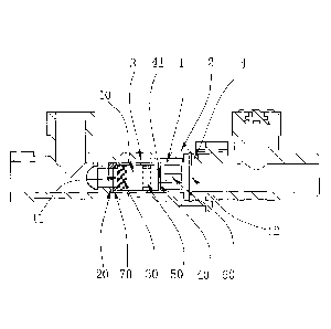
On the constant pressure switch apparatus 100 shown in Figs. 2 and 3, the
baffle
40 may be located inside the flow passage 10. At this time, although the first
blocking
member 30 can slide in the flow passage 10 (of course, the first blocking
member 30
may also rotate around a pivot as shown in Figs. 6a and 6b), the shape of the
cross
section of the first blocking member 30 is matched with that of the flow
passage 10.
For example, the cross section of the flow passage 10 is circular, polygonal
(such as in
a square and rectangle shape) or in any other shapes, and the cross section of
the first
blocking member 30 is also circular, polygonal or in any other shapes.
The first blocking member 30 moves towards the baffle 40 under the impact of
water flow (or under the effect of the pressure difference between the two
sides
thereof), and after the first blocking member 30 moves to the baffle 40, it is
stopped
and limited by the baffle 40 and then stops moving. The position of the baffle
needs to
be selected properly, it is adjacent to the communicating position, and the
baffle 40
limits the first blocking member 30 to the communicating position, so as to
perform
the return water circulation. In consideration that if the baffle 40 is in a
closed
construction, the first blocking member 30 and the baffle 40 will have water
remained
therebetween when the first blocking member 30 moves towards the communicating
position, which results in that the first blocking member 30 cannot be located
completely in the communication position, therefore, the baffle 40 can be
provided
with a first through-hole 41. The first through-hole 41 can completely drain
out the
water between the baffle 40 and the first blocking member 30, so as to
facilitate the
first blocking member 30 to completely expose the discharge hole on the wall
of the
first body 1, and thus the flow passage 10 is in a fully opened state.
In order to facilitate movement of the first blocking member 30 in the flow
14
CA 03001747 2018-04-12
passage 10, a certain distance may present between an outer edge of the first
blocking
member 30 and the flow passage 10, which distance will form slight water
leakage in
the moving process of the first blocking member (which has been described in
the
above). In order to prevent the first blocking member 30 from turning over
under the
impact of water flow and being unable to work normally, the first blocking
member
30 can have a preset thickness in an extension direction of the flow passage
10. Based
on this preset thickness, the first blocking member 30 will not turn over when
moving
in the flow passage 10, and thus can reach the communicating position or can
return
to the blocking position stably.
Continuing to refer to Figs. 2 and 3, a side wall of the first body 1 is
provided
with a second through-hole 50 and a third through-hole 60 which are in
communication with the flow passage 10, and the baffle 40 is located between
the
second through-hole 50 and the third through-hole 60. The second through-hole
50
and the third through-hole 60 are arranged in an extension direction of the
flow
passage 10, in other words, one of the second through-hole 50 and the third
through-hole 60 is a hole from which water flow flows out, while the other one
is a
hole from which the water flow enters. In Fig. 2, the second through-hole 50
is the
hole from which the water flow flows out, the third through-hole 60 is the
hole from
which the water flow enters, and the second through-hole 50 is located
upstream of
the third through-hole 60. Preferably, in order to drain the water flow stably
and
rapidly, a plurality of second through-holes 50 and third through-holes 60 are
distributed evenly on the side wall of the first body 1 in a circumferential
direction
thereof. The present application does not make any limitation to the specific
shapes of
the second through-hole 50 and third through-hole 60. They may be circular
holes,
may be polygonal holes, and may also be irregular shaped holes.
Take the case shown in Fig. 3 as an example, the second through-hole 50 and
the
third through-hole 60 may both be of rectangular structures, and the sides in
a water
flow direction are their long sides. The width of the second through-hole 50
may be
narrower so as to prevent the problem that the first blocking member 30 is
easy to turn
CA 03001747 2018-04-12
over when it is too wide. The overall area of the third through-hole 60 is
larger than
that of the second through-hole 50, and thus an intensity of the side at which
the third
through-hole 60 is located (relative to the baffle 40) is weaker than that of
the side at
which the second through-hole 50 is located. Thus, in some cases, the side at
which
the third through hole 60 is located will be deformed anterior to the side at
which the
second through-hole 50 is located, thereby protecting the side at which the
second
through-hole 50 is located, so as to achieve the purpose of extending the
usage life of
the whole constant pressure switch apparatus 100.
What needs to be explained is that, there are multiple discharge methods
between
the second through-hole 50 and the third through-hole 60, such as setting an
outer
pipe 2 outside to form a sealed chamber by which the second through-hole 50
and the
third through-hole 60 are communicated, besides, a plurality of grooves
recessed from
inside to outside may be provided on the wall of the flow passage 10. It can
be seen
that there are multiple discharge methods between the second through-hole 50
and the
third through-hole 60 in this embodiment, so the present application will not
make
any limitation to this. Meanwhile, this can indicate that: when the first
blocking
member 30 is located at the communicating position, there may be multiple
modes for
the communicating mechanism of the flow passage 10 of the constant pressure
switch
apparatus 100. The embodiments of the present application only function for
schematically illustrating, and are not !imitative to the present application
as should
be understood.
Besides, referring to Fig. 4, a side wall of the first body 1 is provided with
a
fourth through-hole and a fifth through-hole which are in communication with
the
flow passage 10. The communicating position is located between the fourth
through-hole and the fifth through-hole. The outer wall of the first body 1 is
provided
with a communicating pipeline 5 which communicates the fourth through-hole
with
the fifth through-hole. The communicating pipeline 5 allows flow of water
flowing
from the fourth through-hole to the fifth through-hole. and it may be a tube
in
particular. Wherein, the shapes and constructions of the fourth through-hole
and the
16
Cl. 03001747 2018-04-12
filth through-hole can be set with reference to the second through-hole 50 and
the
third through-hole 60 in the above, and descriptions thereof will be omitted
herein.
In the above embodiment, the first body 1 of the constant pressure switch
apparatus 100 may be connected with the cold and hot water pipelines. Besides,
as
shown in Figs. 2 and 3, the constant pressure switch apparatus 100 may also
comprise
an outer pipe 2 which is provided outside the first body 1, while the sucking
member
20 is provided inside the outer pipe 2 and outside the first body 1. Two ends
of the
outer pipe 2 are respectively connected to the cold water pipeline and the hot
water
pipeline, and can be set coaxially with the first body 1 (which is shown as a
tubular
structure in Fig. 3). To be specific, an inner wall of the outer pipe may be
sealingly
connected with the two ends of the first body I respectively, thereby forming
an
annulus 3 communicating the second through-hole 50 with the third through-hole
60
between the first body 1 and the outer pipe 2. When the first blocking member
30 is
located at the communicating position, the circulating waterway realizes
passage
discharge by means of the annulus 3. The outer pipe 2 can be formed by two
detachable parts as shown in Fig. 3, thereby facilitating installation of the
first body 1
in the outer pipe 2. The two parts of the outer pipe 2 can both be three-way
type
structures, so as to provide a cold water outlet end and a hot water outlet
end.
Further, the constant pressure switch apparatus 100 may also comprise a fixing
member 4, the sucking member 20 is adjacent to the inlet 11, the fixing member
4 is
adjacent to the outlet 12 and is capable of extending at least partially into
the outer
pipe 2 to fix the first body I in the outer pipe 2, and the blocking position
includes a
position where the first blocking member 30 abuts the sucking member 20. The
fixing
member 4 may have many constructions, such as a screw, a bolt, and a
connecting
pipe. and the like. Preferably, the fixing member can employ a connecting pipe
to
connect and fix the first body 1 and the outer pipe 2 as shown in Fig. 3. An
end of the
connecting pipe extends into the outer pipe 2, while the other end is in
sealing contact
with an end of the outlet 12 of the first body, and the two are tightly
connected by a
clip.
17
CA 03001747 2018-04-12
Continuing to refer to Figs. 2 and 3, the sucking member 20 is located inside
the
outer pipe 2 and is located outside the first body 1, and it is in a circular
construction
as a whole with an outer diameter larger than the diameter of the flow passage
10. The
inner wall of the outer pipe 2 is provided with steps, and the sucking member
20 can
be located between an end face of the first body I and the steps. By means of
the
abutment of the top of the first body 1, the sucking member 20 can be tightly
clamped
between the first body 1 and the steps. The first blocking member 30 is
attracted by
the sucking member 20 and fits to it, and at this time, the first blocking
member 30
blocks the central through-hole of the sucking member 20, thereby finishing
the
blocking of the flow passage 10. A gasket 70 is provided between the sucking
member
20 and the first blocking member 30 and has a preset thickness. By setting
this gasket
70, on the one hand, it can improve the sealing effect when the first blocking
member
30 and the sucking member 20 fit each other, on the other hand, the open
pressure of
the constant pressure switch apparatus 100 can be controlled according to the
thickness of the gasket 70.
Please refer to Figs. 5a and 5b, which show another preferred embodiment of
the
present application. In this embodiment, the flow passage 10 runs through the
first
body 1. The constant pressure switch apparatus 100 also comprises an outer
pipe 2
(not shown) which is provided outside the first body 1. The first blocking
member 30
is a sleeve with one end closed and having a through-hole at a side wall, the
first
blocking member is sleeved at the end of the outlet 12 of the first body 1 and
its side
wall is located between the first body I and the outer pipe. When the pressure
difference is greater than the attraction force between the first blocking
member 30
and the sucking member 20, the through-hole 31 can be in communication with
the
outlet 12: when the pressure difference is less than the attraction force
between the
first blocking member 30 and the sucking member 20, the first blocking member
30
can block the outlet 12. In this embodiment, the first blocking member 30 may
be of
an annular structure, which is fixedly sleeved on the outer wall of the first
body 1. The
first blocking member 30, the first body 1 and the outer pipe can all be set
coaxially
18
CA 03001747 2018-04-12
=
with respect one another, and the first blocking member 30 can slide along the
axis. In
an opened state of the circulating pump, the first blocking member 30 is
pushed by
water to slide, and then communicates with the flow passage 10 after sliding
for a
preset distance, and therefore the water flow is discharged from the through-
hole 31.
Mier the cyclic water return and heating, the sucking member 20 attracts the
first
blocking member 30 to slide to the blocking position, at this time, the
through-hole 31
is shielded by the wall of the first body 1, and thus the communicated state
of the flow
passage 10 is shutoff. Of course, in this embodiment, the number of the
through-hole
31 may be plural, and the through-holes 31 may also be distributed evenly in a
circumferential direction of the first blocking member 30.
Please refer to Figs. 6a and 6b, which show another feasible embodiment of the
present application. In this embodiment, the flow passage 10 runs through the
first
body 1. At least the part of the flow passage 10 adjacent to the outlet 12 is
arc shaped.
The first blocking member 30 is fixed at the arc shaped flow passage 110 of
the first
body I by a positioning member and can move around the positioning member
along
the arc shaped flow passage 110. When the pressure difference is greater than
the
attraction force between the first blocking member 30 and the sucking member
20, the
first blocking member 30 can move along the arc until the inlet 11 is in
communication with the outlet 12; when the pressure difference is less than
the
attraction force between the first blocking member 30 and the sucking member
20, the
first blocking member 30 can block the flow passage 10. In this embodiment,
the
sucking member 20 may be a stop block type construction, and is located
fixedly in
the flow passage 10. The first blocking member 30 may be a plate first body
with one
end connected on the wall of the flow passage 10 via a rotation shaft. In this
embodiment, in the opening process of the flow passage 10, one end of the
first
blocking member 30 needs to move for a certain distance along the arc shaped
flow
passage 110 to open the flow passage 10, so, the constant pressure switch
apparatus
100 provided in this embodiment can effectively avoid the phenomenon of series
flow
of cold and hot water, and thus has better stability.
19
CA 03001747 2018-04-12
It can be seen that, in the present application, the constant pressure switch
apparatus 100 provides a lot of schematic and preferred embodiments to support
the
claims of the present application, however, it should be understood that the
above
embodiments should not have limitations to the present application. Any
changes
made by the persons skilled in the art based on the present applicant should
fall into
the protection scope of the present application without lacking the essence
provided
by the present application.
Another embodiment of the present application also provides a water heating
system, comprising: a water heater having a water inlet and a water outlet; a
water
inlet pipe connected to the water inlet; a water outlet pipe connected to the
water
outlet; a cold water pipe in communication with the water inlet pipe; a water
mixing
valve connected between the cold water pipe and the water outlet pipe; a pump
in
communication with the water inlet pipe or the water outlet pipe; a constant
pressure
switch apparatus connected between the cold water pipe and the water outlet
pipe in
parallel with the water mixing valve.
The constant pressure switch apparatus comprises: a first body inside which a
flow passage is provided, the flow passage having an inlet and an outlet; the
inlet
being in communication with the water outlet pipe and the outlet being in
communication with the cold water pipe: a first blocking member and a sucking
member that can be magnetically attracted to each other, the sucking member is
located between the water outlet pipe and the inlet; a first blocking member,
the first
blocking member having a blocking position and a communicating position that
are
spaced apart with a preset distance; the first blocking member being able to
move
towards the communicating position when a pressure difference between both
sides of
the first blocking member in a direction from the inlet to the outlet is
greater than an
attraction force between the first blocking member and the sucking member; the
first
blocking member being able to move towards the blocking position when a
pressure
difference between both sides of the first blocking member in a direction from
the
inlet to the outlet is less than an attraction force between the first
blocking member
= 84255662
and the sucking member.
Please refer to Figs. 7 and 8, which show another embodiment of this
application that
provides a water heating system. The water heating system comprises: a water
heater 1; a water
inlet and a water outlet which are connected to the water heater 1; a water
inlet pipe 2 in
communication with the water inlet ; a water outlet pipe 3 in communication
with the water outlet;
a water return pipe 4 of which a first end 41 is in communication with the
water inlet pipe 2 and a
second end 42 is in communication with the water outlet pipe 3; the water
inlet pipe 2, the water
heater 1, the water outlet pipe 3 and the water return pipe 4 form a
circulation loop; the circulation
loop is provided with a circulation pump 5; a water mixing valve 6 in
communication with the
water outlet pipe 3; the water mixing valve 6 is disposed downstream the
second end 42 of the
water return pipe 4; a constant pressure switch apparatus which is close to
the water mixing
valve 6 and disposed on the water return pipe 4.
The constant pressure switch apparatus includes: a first body inside which a
flow passage is
provided, the flow passage having an inlet and an outlet; the inlet being in
communication with
the water outlet pipe and the outlet being in communication with the water
return pipe; a first
blocking member and a sucking member that can be magnetically attracted to
each other, the
sucking member is located between the water outlet pipe and the inlet; the
first blocking member
having a blocking position and a communicating position that are spaced apart
with a preset
distance; the first blocking member being able to move towards the
communicating position when
a pressure difference between both sides of the first blocking member in a
direction from the inlet
to the outlet is greater than an attraction force between the first blocking
member and the sucking
member; the first blocking member being able to move towards the blocking
position when a
pressure difference between both sides of the first blocking member in a
direction from the inlet to
the outlet is less than an attraction force between the first blocking member
and the sucking
member.
In order to simplify the pipeline structure and reduce the usage amount of the
piping material,
the constant pressure switch apparatus is adjacent to the water mixing valve.
The cold water and
hot water are mixed by the water mixing valve and then flow out, the mixing
ratio of the cold
water and hot water can be controlled by the water mixing valve, and thereby
the temperature of
the discharged water is controlled.
21
CA 3001747 2019-08-08
CA 03001747 2018-04-12
In this embodiment, the shapes, constructions and acting modes of the constant
pressure switch apparatus can all be set with reference to the constant
pressure switch
apparatus provided in the above mentioned embodiments, and descriptions
thereof
will be omitted.
The inventor also found the following problems when using existing water
heater: the prior art disposes a water return pipe between a water outlet pipe
and a water inlet
pipe of the water heater, and disposes a circulation pump on a circulation
loop composed of the
water heater, the water outlet pipe and the water return pipe. When the user
wants to use water, the
circulation pump is opened in advance to drive water in the circulation loop
for a circulation
preheat, and draw cold water between the water consuming point and the water
mixing valve back
to the water heater for heating. This manner requires re-laying the water
return pipe, but according
to studies, most users buy the water heater after a decoration, and very few
users mount the water
return pipe in advance. So the technical solution that requires re-laying the
water return pipe limits
the popularization of the technique.
Another solution existed in the prior art to solve the above technical problem
is to provide a
pipeline connected in parallel with the water mixing valve of the water
consuming point and
disposed between the water outlet pipe and the cold water pipe supplying cold
water to the water
consuming point, so that the water heater, the water outlet pipe, the parallel
pipeline and the cold
water pipe form a circulation pipeline. This solution sufficiently utilizes
the original cold water
pipe in the user's house, without re-laying the water return pipe, and the
construction is simple and
convenient. But when the above solution is adopted, water in the cold water
pipe is continuously
heated during circulation after the user starts the preheat circulation
function. If temperature of
water in the cold water pipe is too high, water flowing out of the water
mixing valve will be hot
after the user opens the water mixing valve at the water consuming point, and
there is a risk of
scalding the user.
In order to solve the above problem, please refer to Figs. 7 and 10, One
embodiment of this
application provides a water heating system100. this system 100 comprises: a
water heater I; a
water inlet and a water outlet which are connected to the water heater 1; a
water inlet pipe 2 in
communication with the water inlet; a water outlet pipe 3 in communication
with the water outlet;
22
CA 03001747 2018-04-12
a water return pipe 4 of which a first end 41 is in communication with the
water inlet pipe 2 and a
second end 42 is in communication with the water outlet pipe 3: the water
inlet pipe 2. the water
heater I. the water outlet pipe 3 and the water return pipe 4 form a
circulation loop: the circulation
loop is provided with a circulation pump 5; a water mixing valve 6 in
communication with the
water outlet pipe 3; the water mixing valve 6 is disposed downstream the
second end 42 of the
water return pipe 4; a temperature control part 7 which is close to the water
mixing valve 6 and
disposed on the water return pipe 4; the temperature control part 7 can cut
off communication
between the water outlet pipe 3 and the water return pipe 4 when temperature
of water flowing
through the temperature control part 7 reaches a predetermined temperature.
The water heater 1 is
one of a gas water heater, an electric water heater. and a heat-pump water
heater. Preferably, the
water heater is a gas water heater.
In a specific embodiment, the water return pipe 4 is a pipeline additionally
disposed between
the water outlet pipe 3 and the water inlet pipe 2; the water return pipe 4
has the first end 41 in
communication with the water outlet pipe 3, and the second end 42 in
communication with the
water inlet pipe 2; the water return pipe 4 is provided with the temperature
control part 7 that is
close to the water mixing valve 6; the temperature control part 7 cuts off
communication between
the water outlet pipe 3 and the water return pipe 4 when temperature of water
flowing through the
temperature control part 7 exceeds a predetermined temperature. By disposing
the temperature
control part 7 in the water return pipe 4, it prevents temperature of water in
the water return pipe 4
from being too high, energy resources from being wasted, and the user from
suffering unnecessary
loss.
In a specific embodiment, the water return pipe 4 is composed of a parallel
pipeline 9 where
at least pan of the cold water pipe 8 and the water mixing valve 6 are
connected in parallel; the
cold water pipe 8 has the first end in communication with the water mixing
valve 6, and the
second end in communication with the water inlet pipe 2; the parallel pipeline
9 has the first end in
communication with the water outlet pipe 3, and the second end in
communication with the cold
water pipe 8; the temperature control part 7 is disposed in the parallel
pipeline 9, or the cold water
pipe 8 close to the water mixing valve 6. In this embodiment, when a cold
water segment between
the water heater and the water consuming point is to be solved, the water
return pipe 4 does not
need to he re-disposed, and the temperature control part 7 is disposed in the
parallel pipeline 9
23
CA 03001747 2018-04-12
composing the water return pipe 4, or the cold water pipe 8 close to the water
mixing valve 6; the
temperature control part 7 cuts off communication between the water outlet
pipe 3 and the cold
water pipe 8 when temperature of water flowing through the temperature control
part 7 exceeds
the predetermined temperature, so as to prevent the temperature in the cold
water pipe 8 from
being too high. Preferably, the temperature control part 7 is disposed on the
parallel pipeline 9. If
temperature of water in the cold water pipe 8 is too high. water flowing out
of the water mixing
valve 6 will be too hot when the user starts to use water at the water
consuming point, and there is
risk of scalding the user.
Referring to Figs. 9 and 10. the temperature control part 7 of this
application comprises: a
second body 71; a first inlet 72 and a first outlet 73 that are disposed on
the second body 71; a
second blocking member 74 that is movably disposed on the second body 71; the
second blocking
member 74 has a first position where the first inlet 72 can be communicated
with the first outlet 73
and a second position where the first inlet 72 can be separated from the first
outlet 73; a
thermosensitive element 75 disposed on the second body 71 and capable of
driving the second
blocking member 74 to move to the second position at the predetermined
temperature. Preferably,
the thermosensitive element 75 is disposed downstream the first inlet 72.
Further, the second body
71 is further provided with an elastic reset element 76 which applies a force
toward the first
position to the second blocking member 74. Specifically, the second blocking
member 74 may be
disposed inside or partially inside the second body 71, or partially outside
the second body 71.
which is not limited herein.
In a specific embodiment, the temperature control pan 7 may be a first one-way
valve which
can he opened in a direction from the first inlet 72 to the first outlet 73.
The application of the
embodiment is convenient, only requiring a one-way valve having the
thermosensitive element 75.
When sensing that the temperature of water in the water return pipe or flowing
into the cold water
pipe 8 is too high, the thermosensitive element 75 drives the second blocking
member 74 to block
communication between the first inlet and the second inlet, and then cut off
communication
between the water outlet pipe 3 and the water return pipe 4, so as to prevent
the temperature of
water in the water return pipe 4 from continuously rising. In this embodiment,
the second blocking
member 74 may be a valve core.
Referring to Figs. 9 and 10, in a specific embodiment, the second body 71 is
hollow and
24
CA 03001747 2018-04-12
tubular, the second blocking member 74 is disposed in the second body 71, the
second blocking
member 74 comprises a first surface 741, a second surface 742 and a side wall
that has a
predetermined thickness; the first inlet 72 is disposed on a side wall of the
second body 71, one
end of the second body 71 that faces the water outlet pipe 3 is at least
partially sealed; the second
blocking member 74 comprises a first through hole 743 which runs through the
first surface 741
and the second surface 742; a first position of the second blocking member 74
is between the first
inlet 72 and the first outlet 73, and when the second blocking member 74 is at
the first position,
the first through hole 743 communicates the first inlet 72 with the first
outlet 73; when the second
blocking member 74 is at a second position, the side wall of the second
blocking member 74
blocks the first inlet 72. The second blocking member 74 may also be a solid
construction. When
the second blocking member 74 is a solid construction, the first position of
the second blocking
member 74 is located upstream the first inlet 72, and the second position of
the second blocking
member 74 is located between the first inlet 72 and the first outlet 73.
In a specific embodiment, referring to Figs. 9 and 10, the circulation
pipeline is provided with
a second one-way valve which may be disposed upstream the temperature control
part 7. and
which may be integrated with or separated from the temperature control part 7.
The second
one-way valve may he an ordinary one-way valve, or a constant pressure switch
valve. Preferably,
the second one-way valve is a constant pressure switch valve 12. In a specific
embodiment, the
constant pressure switch valve 12 is disposed in the parallel pipeline 9 and
located upstream the
temperature control part 7. The constant pressure switch valve 12 comprises: a
valve body 121
(The valve body 121 is similar to the first body structure of the constant
pressure switch
apparatus)which is provided with a flow channel therein: the flow channel has
a second inlet 123
and a second outlet 124: a second blocking member 125 and an attractable
member 126 which can
be magnetically attractive to each other; the second blocking member 125 has a
blocking position
for partitioning the second inlet 123 from the second outlet 124 and a
communicating position for
communicating the second inlet 123 with the second outlet 124, which are
spaced apart by a preset
distance; when a difference between pressures at two sides of the second
blocking member 125 in
a direction from the second inlet 123 to the second outlet 124 is lamer than
an attractive force
between the second blocking member 125 and the attractable member 126, the
second blocking
member 125 can move toward the communicating position; when a difference
between pressures
CA 03001747 2018-04-12
at two sides of the second blocking member 125 in a direction from the second
inlet 123 to the
second outlet 124 is smaller than an attractive force between the second
blocking member 125 and
the attractable member 126, the second blocking member 125 can move toward the
blocking
position. The second blocking member 125 cannot open the constant pressure
switch valve 12
unless moving for a preset distance, so it is impossible to open the constant
pressure switch
valve 12 unless the difference between pressures at two sides of the second
blocking member 125
shall be remained to be larger than the attractive force between the second
blocking member 125
and the attractable member 126 for a period of time, so as to effectively
avoid the problem of
cross-flow of cold and hot water caused by the water pressure fluctuation in
the cold water pipe 8
and the water outlet pipe 3. Specifically, the constant pressure switch valve
12 and the temperature
control part 7 form an integral structure. Further, the valve body 121 and the
second body 71 form
an integral structure. The second outlet 124 is disposed on a side wall of the
valve body 121; a
baffle plate 127 is disposed between the valve body 121 and the second body
71; the second outlet
123 and the first inlet 72 are disposed at two sides of the baffle plate 127,
respectively: a second
through hole may be disposed in the baffle plate 127 to drain water remained
between the baffle
plate 127 and the second blocking member 125, so as to reduce the running
resistance of the
second blocking member 125. A housing 13 may be disposed outside the integral
structure of the
valve body 121 and the second body 71, and the housing 13 may be a part of the
parallel pipeline
9: the attractable member 126 is close to the second inlet 123, and disposed
in the housing 13
while located outside the valve body 121; the second blocking member 125 is
disposed in the
valve body 121. In order to fix the integral structure of the valve body 121
and the second body
71 in the housing 13, a fixing member 14 close to the first outlet 73 is
further comprised. The
fixing member 14 can at least partially extend into the housing 13 to fix the
second body 71 and
the valve body 121 within the housing 13, a gap is disposed between the
integral structure of the
second body 71 and the valve body 121 and an inner wall of the housing 13; the
gap is a channel
for communicating the second outlet 124 and the first inlet 72; the fixing
member 14 is provided
with a flow channel therein, and the first outlet 73 is in communication with
the flow channel
within the fixing member 14. A portion of the fixing member 14 that extends
into the housing 13
is in threaded connection to the housing 13. During the implementation. the
length of an integral
unit composed of the housing 13 and the fixing member 14 may be adjusted
through the number
26
=
Cl. 03001747 2018-04-12
of turns of the threads to match the actual mounting. In addition, besides the
threaded connection,
other feasible embodiment includes: the portion of the fixing member 14 that
extends into the
housing 13 is provided with a first boss 141 and a second boss 142 that extend
towards the
housing 13 and are spaced by a preset distance, the second boss 142 is
disposed downstream the
first boss 141, the housing 13 is provided with a third boss 143 that extends
toward a center of the
housing 13 and has a predetermined thickness at a position of the housing 13
that is close to the
first outlet 73, the third boss 143 is provided with an opening through which
the first boss extends
141, the first boss 141 is rotated by a predetermined angle after extending
through the opening so
that the third boss 143 can be located between the first boss 141 and the
second boss 142. Further,
the preset distance between the first boss 141 and the second boss 142 is
larger than a preset
thickness of the third boss 143. Since the preset distance between the first
boss 141 and the second
boss 142 is larger than the preset thickness of the third boss 143, the fixing
member 14 has a
certain movable range, and through this movable connection mode, the purpose
of adjusting the
length of an integral unit composed of the housing 13 and the fixing member 14
can also be
achieved.
Any numeral values cited herein includes all values of the lower values and
the
upper values from the lower limiting value to the upper limiting value, in
increments
of one unit, provided that there is a separation of at least two units between
any lower
value and any higher value. For example, if the value illustrating the number
or
process variable (such as temperature, pressure and time, etc.) of a component
is from
1 to 90, preferably from 20-80, and more preferably from 30 to 70, then the
purpose is
to explain that the Description also explicitly enumerates values such as 15
to 85, 22
to 68, 43 to 51 and 30 to 32. For values which are less than one, one unit is
considered
to be 0.0001, 0.001, 0.01 or 0.1 as appropriate. These are only examples of
what is
specifically intended, and all possible combinations of numerical values
between the
lowest value and the highest value enumerated, are all expressly stated in the
Description in similar ways.
Unless otherwise stated, all numerical ranges include the endpoints and all
numbers that fall between the endpoints. The use of "about" or "approximately"
in
27
84255662
=
connection with a range applies to both ends of the range. Therefore, "about
20 to 30" is intended
to cover "about 20 to about 30", inclusive of at least the specified
endpoints.
The term "substantially formed of ..." describing combinations should include
the
determined elements, components, parts or steps as well as other elements,
components, parts or
steps that do not affect the basic novel features of the combination in
substance. The use of the
terms "contain" or "include" to describe the combinations of elements,
components, parts or steps
herein also give rise to the embodiments constituted substantially by these
elements, components,
parts or steps. The term "may" as used herein is intended to explain that any
attribute included by
the "may" as described is selectable.
Plural elements, components, parts or steps can be provided by a single
integrated element,
component, part or step. Alternatively, a single integrated element,
component, part or step might
be divided into separate plural elements, components, parts or steps. The
disclosed "a" or "an"
used for describing elements, components, parts or steps do not exclude other
elements,
components, parts or steps.
It is to be understood that the above description is intended to be
graphically illustrative and
not restrictive. Many embodiments and applications other than the examples
provided would be
apparent to those of skill in the art upon reading the above description
Therefore, the scope of the
present teaching should be determined not with reference to the above
description but should,
instead, be determined with reference to the appended claims, along with their
full scope of
equivalents. The omission in the foregoing claims of any aspect of subject
matter that is disclosed
herein is not a disclaimer of such subject matter, nor should it be regarded
that the inventors did
not consider such subject matter to be part of the disclosed inventive subject
matter.
28
CA 3001747 2019-08-08