Note: Descriptions are shown in the official language in which they were submitted.
-1-
WEAR RESISTANT STUDS FOR VEHICLES
BACKGROUND OF THE INVENTION
1. Field of Invention
The present invention relates generally to studs for tracked vehicles and in
particular to wear resistant studs for use in tracked vehicles and methods for
forming wear resistant studs.
2. Description of Related Art
Tracked vehicles are useful in many areas where softer ground would impede
the movement of wheeled vehicles. Disadvantageously, due to the lower
ground pressure such tracks may suffer from reduced traction on the ground
and particularly on frozen ground or ice.
Previous attempts to provide studs in tracked vehicles have not need
satisfactory. In particular, many such studs have bred embedded or passed
through the track and commonly formed of steel. Such steel studs however
are known to wear quickly when used on pavement or asphalt are well.
Tungsten carbide is a material which is known to have excellent wear
properties but is brittle and therefore not suitable for forming the entire
stud.
Additionally tungsten carbide is not commonly able to be welded and is
therefore commonly brazed to an underlying metal. However, brazing is
known to be weaker than welding.
SUMMARY OF THE INVENTION
According to a first embodiment of the present invention there is disclosed a
method for forming a wear resistant stud for a vehicle comprising providing an
elongate threaded stud member having a top surface, locating a body of
tungsten carbide on the top surface, surrounding the body of tungsten carbide
with a weld pool and while the weld pool is hot, slowly cooling the weld pool.
CA 3002190 2018-04-19
-2-
The slowly cooling step may comprise applying heat to the weld pool through
friction. The slowly cooling step may comprise applying a rotating wire brush
to the weld pool. The weld pool may completely cover the body of tungsten
carbide and the top surface.
According to a further embodiment of the present invention there is disclosed
a
wear resistant stud for a vehicle comprising an elongate threaded stud
member having a top surface, a body of tungsten carbide on the top surface
and a weld pool surrounding the body of tungsten carbide and the top surface
of the stud member wherein the weld pool is slowly cooled from a hot applied
state
The top surface may be located on a head of the stud member. The stud
member may include a bottom collar adapted to retain a track of the vehicle
between the bottom nut and the head. The wear resistant stud may further
comprise a top collar adapted to retain the track between the top and bottom
collars.
The body of tungsten carbide may be located within a bore in the top surface
of the stud member. The top surface may be located on a top member having
at least two elongate threaded stud members extending substantially
perpendicularly therefrom. The top member may comprise a bar extending
perpendicularly between the at least to elongate threaded stud members.
The top member may comprise a triangular member extending along a plane
perpendicular to the at least to elongate threaded stud members.
The body of tungsten may comprise a length of tungsten carbide having a
length less than the top surface. The body of tungsten carbide may have a
triangular cross section. The weld pool may be slowly cooled with the use of
a rotary wire brush. The weld pool may cover the body of tungsten carbide
completely.
CA 3002190 2018-04-19
-3-
According to a further embodiment of the present invention there is disclosed
a
kit for forming a wear resistant member for a vehicle comprising at least one
stud comprising an elongate threaded stud member having a top surface, a
body of tungsten carbide on the top surface, a weld pool surrounding the body
of tungsten carbide and the top surface of the stud member wherein the weld
pool is slowly cooled from a hot applied state. The kit further comprises a
gripping body adapted to be located on an outside surface of the track and
having a bore therethrough corresponding to each stud, wherein the at least
one stud is operable to be passed through a corresponding bore in the
gripping body and the track so as to secure the gripping body to the track.
Other aspects and features of the present invention will become apparent to
those ordinarily skilled in the art upon review of the following description
of
specific embodiments of the invention in conjunction with the accompanying
figures.
BRIEF DESCRIPTION OF THE DRAWINGS
In drawings which illustrate embodiments of the invention wherein similar
characters of reference denote corresponding parts in each view,
Figure 1 is a side view of a track for use on tracked vehicle having a
plurality of studs formed according to a first embodiment of the
present invention.
Figure 2 is a perspective view of one of the studs of figure 1 being
passed
through the track of the vehicle.
Figure 3 is a side view of the stud of figure 1 being formed at a first
step
with a tungsten carbide element located on a top surface thereof.
Figure 4 is a side view of the stud of figure 1 being formed at a
second
step with a weld pool being formed around the tungsten carbide
element.
Figure 5 is a perspective view of an apparatus for forming elongate
portions of tungsten carbide into elements for use on the stud of
figure 1.
CA 3002190 2018-04-19
-4-
Figure 6a-6d are perspective views of studs for use in a tracked vehicle
according to further embodiments of the present invention.
Figures 7a-7b are perspective views of the studs for use in a tracked vehicle
according to further embodiments of the present invention.
Figure 8 is a perspective view of a stud according to a further
embodiment of the present invention at a first stage of being
formed.
Figure 9 is a perspective view of the stud of Figure 8 at a third
stage of
being formed.
Figure 10 is a perspective view of the stud of Figure 8 at a third stage of
being formed.
Figure 11 is a cross sectional view of the stud of Figure 8
positioned
through a track of a vehicle.
Figure 12 is a perspective view of a stud for adjusting the stud of
Figure 8.
Figure 13 is a side view of a wheel having a plurality of studs passed
therethrough.
Figure 14 is a cross sectional view of the wheel of Figure 13.
Figure 15 is a top plan view sectional view of section of track
having a
plurality of studs inserted therethrough.
DETAILED DESCRIPTION
Referring to Figure 1, continuous track 8 for use on a tracked vehicle is
shown
generally at 8 with at least one wear resistant stud 10 passed therethrough.
The stud 10 as illustrated further in Figure 2 comprises at least one elongate
threaded member 12 with top member 14 and bottom collar 20 adapted to
retain the track 8 therebetween when the threaded member 12 is passed
therethrough. The top member 14 includes a wear resistant body 30 as will
be further described below.
The threaded member 12 may comprise any elongate member extending
between top and bottom ends, 15 and 17, respectively wherein the top
member 14 is located at the top end 15. The threaded member may comprise
any suitable threaded member, however in practice it has been found that
CA 3002190 2018-04-19
-5-
grade 8 type fasteners have been particularly useful. The threaded member
12 may also be selected to have a diameter to provide a suitable strength to
the stud 10 according to known methods. In particular, it has been found that
diameters between 3/8 and 1 1/4 inch (10 and 32 mm) has been useful
although it will be appreciated that other sizes may be useful as well. The
top
member 14 may comprise a bolt head of the threaded member as illustrated
in Figure 2 or other structures adapted to provide a top surface as will be
further described below. The bottom collar 20 is threadably received on the
threaded member 12. As illustrated in Figure 3 the bottom collar 20 may be
formed with a planar member 22 and a cylindrical portion 24 extending
therefrom although it will be appreciated that other collar types may be
utilized
as well. Optionally, the threaded member 12 may also include a top collar 21
formed similar to and positioned on the threaded member in mirror to the
bottom collar as well as a washer 23 as is commonly known. The planar
member 22 may optionally include a plurality of key bores 26 extending
therethrough at a position adapted to receive a key or wrench for tightening
the bottom collar 20 on the threaded member 12. It will be appreciated that
any wrench type may be utilized as well such as by way of non-limiting
example, hex nuts or the like. The top member 14 may be a separate body
secured on the threaded member 12 or may optionally be co-formed with the
threaded member 12. The top member 14 defines a top surface 16 adapted
to have the wear resistant body 30 formed thereon as will be further described
below.
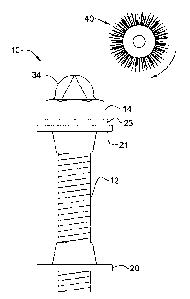
Referring to Figure 3, the wear resistant body 30 of the stud 10 is formed by
first locating a body of tungsten carbide 32 on the top surface 16 of the top
member 14. As illustrated in Figure 3, the body of tungsten carbide 32 has a
triangular cross section, although it will be appreciated that any other cross
section, such as, by way of non-limiting example, square, rectangular or round
may also be utilized. As illustrated in Figure 4, after the body of tungsten
carbide 32 has be located at the desired location a weld pool 34 may be
formed therearound so as to secure the body of tungsten carbide 32 to the top
surface 16. In particular, the weld pool 34 is formed to surround and cover
CA 3002190 2018-04-19
-6-
the tungsten carbide body 32 as well as matingly engage the top surface 16.
Thereafter, a rotary wire brush 40 is applied to the weld pool 34 to apply
heat
thereto and reduce the rate of cooling of the weld pool 34. It will be
appreciated that the slowed cooling of the weld pool 34 will assist with
adhesion between the weld pool and the tungsten carbide body as well as
reducing brittleness of the weld pool. After sufficient cooling, the wire
brush
40 is removed leaving the finished wear resistant body 30. It will be
appreciated that the amount of time necessary will be dependant upon the
size of the weld. By way of non-limiting example, it has been found that
slowly cooling through the use of the wire brush to a temperature of
approximately 1000 degrees Fahrenheit (500 degrees Celsius) has been
useful. In practice, it has been found that a MIG welding process utilizing
0.045" ER70S-6 welding wire and an argon/carbon dioxide shielding gas
blend with a carbon dioxide content of approximately 25% has been found to
be effective.
Turning now to Figure 5, an apparatus 50 for breaking lengths of tungsten
carbide into shorter lengths for use in the present wear resistant studs is
illustrated. The apparatus 50 comprises a bottom support plate 52 and a top
threaded press 58 adapted to apply a downward force to a length of tungsten
carbide stock 31 located on the support plate 52. The support plate 52
includes a gap 56 extending transverse to the tungsten carbide stock 31 at a
position aligned with the threaded press 58. In operation, the tungsten
carbide stock 31 may be located at a position corresponding to the length of
tungsten carbide stock 31 wished to be separated from the larger piece.
Thereafter, the threaded press 58 may be turned downward to engage upon
the tungsten carbide stock 31 and break it at the location of the gap 56. It
will
be appreciated that other methods of forming the tungsten carbide to the
desired length may also be utilized. As illustrated in Figure 5, the press 85
may include a sharpened end point adapted to apply a point load to the
tungsten carbide stock 31 above the gap 56.
CA 3002190 2018-04-19
-7-
Turning now to Figures 6a through 6d, alternative embodiments of wear
resistant studs are illustrated. In particular, as illustrated in Figure 6a,
the
wear resistant studs 10 may be passed through a t-bar 70 formed of first and
second channel sections, 72 and 74, respectively. As illustrated in Figure 15,
the first channel section 72 may be aligned with a lengthwise direction of the
track 8 wherein the second channel section 74 may be transverse to the track
8. Furthermore, a bar claw 76 may be formed with the top member 14 being
formed by a perpendicular bar 78 extending between a pair of threaded
members 12 as illustrated in Figure 6b wherein the bar claw 76 may be
positioned transverse or angularly relative to the track 8 as illustrated in
Figure 15. As illustrated in Figure 6c, a v-shaped claw 80 may be also be
formed with the top member formed in a triangular shape 82. It will be
appreciated that although a triangular shape is illustrated for the v-shaped
claw, any other shape such as, by way of non-limiting example, circular,
rectangular or irregular may also be utilized. Although the v-shaped claw 80
is illustrated in Figure 15 as having the threaded members 12 longitudinally
along the track, it will be appreciated that other orientations such as
transverse or diagonal on the track may also be utilized.
Turning now to Figures 7a through 7b, alternative embodiments of wear
resistant studs are illustrated. In particular, as illustrated in Figure 7a,
the
wear resistant studs 90 include an additional nut 92 below the top member 14
so as to space the wear resistant body 30 further from the track 8.
Additionally, for use on metal tracks, the wear resistant stud 94 as shown in
Figure 6b may include a self locking or nylock nut 96 below the top member
14 wherein a double nut 98 is provided to clamp the wear resistant stud 94 to
the back side of the track. In operation, a user may loosen the double nuts 98
and position the self locking nut 96 to provide a desired height to the wear
resistant body 30. Thereafter the double nuts 98 may then be retightened to
secure the stud to the track.
Turning now to Figures 8 through 10, an adjustable wear resistant stud 100 is
illustrated. The adjustable wear resistant stud 100 comprises an elongate
CA 3002190 2018-04-19
-8-
threaded member 102 member extending between top and bottom ends, 104
and 106, respectively. The top end 104 defines the top surface 108 and is
formed without a head portion and includes a bore 110 into the top surface
108. As illustrated, the bore 110 may be a hex socket or the like as are
commonly known. The body of tungsten carbide 32 is sized to fit within the
bore 110 in a lengthwise configuration as illustrated in Figure 8. Thereafter,
as illustrated in Figure 9, the weld pool 34 is formed around the body of
tungsten carbide 32 and the top surface 108 so as to cover the body of
tungsten carbide 32 as set out above. As illustrated in Figure 10, top and
bottom collars 21 and 20 may then be threadably located on the threaded
member 102 as set out above such that the top edge of the top collar 21 is
substantially aligned with the top end 104 of the threaded member.
Thereafter, a liquid weld 120 or other suitable liquid adhesive may be applied
to the top collar 21 and the weld pool so as to temporarily secure the top
collar at the top position.
In operation, the stud may be secured within the track as illustrated in
Figure
11 with reference to the embodiments of Figures 8-10. In particular a hole 6
may be bored through the track 8 by any known means and the threaded
member 102 passed therethrough with the top and bottom collars 21 and 20
secured to opposite ends to clamp the track 8 therebetween. Optionally, a
bushing 124, such as a disk of Teflon or other suitable material may be placed
between the top collar 21 and the track 8 to reduce wear. During operation of
the vehicle, it will be appreciated that the weld pool 34 will wear at a
faster
rate than the body of tungsten carbide 32 due to the weld pool being formed
of a softer material. In such events, the tungsten carbide 32 will then be
exposed providing a more wear resistant finish which is held in place by the
remaining weld pool therearound.
With reference to Figure 10, during a short period of operation, the liquid
weld
120 will be abraded away permitting the top collar 21 to be rotated relative
to
the threaded member. In such case, the height of the wear resistant body 30
may then be raised by loosening the bottom collar 20, and repositioning the
CA 3002190 2018-04-19
-9-
top collar 21 at the desired height after which the bottom collar 20 may then
be retightened. A socket 130 for use in loosening and tightening the top and
bottom collars 20 and 21 is illustrated in Figure 12 both on to the track and
also for use in assembling and torqueing the top and bottom collars to the
threaded member 12. The socket 130 includes a central bore 132 sized to
pass the wear resistant body 30 and the cylindrical portion 24 of the top or
bottom collar 21 or 20 therethrough and a plurality of pins 134 corresponding
to the locations of the key bores 26.
Turning now to Figures 13 and 14, a rubber wheel 150 may also be adapted
to receive the wear resistant studs disclosed above therein. In particular,
the
rubber wheel may be formed of first and second hubs, 152 and 154,
respectively secured together with nuts and bolts, 156 and 158, as are
commonly known. A solid rubber cylinder 160 may be disposed therearound
having an overhang portion 162 adapted to extend .beyond the first and
second hubs 152 and 154. The overhand portion 162 is selected to provide a
sufficient distance for the studs to pass through such as, by way of non-
limiting example, between 1 and 6 inches (25 and 152mm). It will also be
appreciated that the rubber cylinder will have a thickness selected to provide
sufficient strength to maintain the studs in contact with a ground surface. In
practice, it has been found that a thickness of between 2 and 4 inches (51 and
102 mm) has been useful although it will be appreciated that other
thicknesses may be useful as well. As illustrated, the wear resistant studs 10
may be passed through the overhang portion 162.
While specific embodiments of the invention have been described and
illustrated, such embodiments should be considered illustrative of the
invention only and not as limiting the invention as construed in accordance
with the accompanying claims.
CA 3002190 2018-04-19