Language selection

Search

Patent 3002333 Summary

Third-party information liability

Some of the information on this Web page has been provided by external sources. The Government of Canada is not responsible for the accuracy, reliability or currency of the information supplied by external sources. Users wishing to rely upon this information should consult directly with the source of the information. Content provided by external sources is not subject to official languages, privacy and accessibility requirements.

Claims and Abstract availability

Any discrepancies in the text and image of the Claims and Abstract are due to differing posting times. Text of the Claims and Abstract are posted:

  • At the time the application is open to public inspection;
  • At the time of issue of the patent (grant).
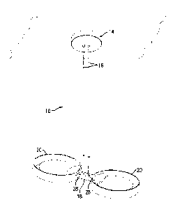
(12) Patent: (11) CA 3002333
(54) English Title: RING-SHAPED LIGHTS WITH EDGE EFFECT
(54) French Title: LUMIERES EN FORME D'ANNEAU A EFFET DE REBORD
Status: Deemed Expired
Bibliographic Data
(51) International Patent Classification (IPC):
  • F21V 17/06 (2006.01)
  • F21K 9/00 (2016.01)
  • F21S 8/06 (2006.01)
  • F21V 5/04 (2006.01)
(72) Inventors :
  • SONNEMAN, ROBERT A. (United States of America)
(73) Owners :
  • CONTEMPORARY VISIONS, LLC
(71) Applicants :
  • CONTEMPORARY VISIONS, LLC (United States of America)
(74) Agent: MBM INTELLECTUAL PROPERTY AGENCY
(74) Associate agent:
(45) Issued: 2020-02-11
(22) Filed Date: 2018-04-20
(41) Open to Public Inspection: 2018-10-27
Examination requested: 2018-04-20
Availability of licence: N/A
Dedicated to the Public: N/A
(25) Language of filing: English

Patent Cooperation Treaty (PCT): No

(30) Application Priority Data:
Application No. Country/Territory Date
15/499,300 (United States of America) 2017-04-27

Abstracts

English Abstract

A light for incorporating in a pendant includes a rim with an inner surface, a housing protecting a light source and a lens with major and minor lateral surfaces and top and bottom surfaces. Light beams from the light source (such an array of LEDs) enters the lens and hit the side of the rim. In addition, the light beams are refracted by dimples up and down from the lens.


French Abstract

Une lampe pour une intégration dans un pendentif comprend un bord ayant une surface interne, un boîtier protégeant une source de lumière et une lentille ayant des surfaces latérales principales et mineures et des surfaces supérieure et inférieure. Des faisceaux lumineux provenant de la source de lumière (un tel réseau de DEL) pénètrent dans la lentille et frappent le côté du bord. De plus, les faisceaux lumineux sont réfractés par des fossettes vers le haut et vers le bas à partir de la lentille.

Claims

Note: Claims are shown in the official language in which they were submitted.

THE EMBODIMENTS OF THE INVENTION FOR WHICH AN EXCLUSIVE
PROPERTY OR PRIVILEGE IS CLAIMED ARE DEFINED AS FOLLOWS:
1. A light, comprising:
a circular rim extending continuously about an axis and having an inner
surface
defining an internal space;
a housing attached to the inner surface of said rim such that said housing is
at least
substantially disposed within said internal space of said rim;
a light source disposed inside said housing and arranged to selectively
generate a beam
of light; and
a lens disposed and supported in said internal space of said rim by said
housing, said
lens having a first lateral surface and a second lateral surface delimiting an
outer periphery of
said lens, said first lateral surface being concave and transparent and being
positioned to
receive said beam of light and said second lateral surface being convex and
concentric with
said circular rim.
2. The light of claim 1, wherein said housing has a lateral opening and
said lens extends
though said lateral opening with said first lateral surface disposed adjacent
to said light
source.
3. The light of claim 2, wherein said lens includes a house engaging
member, said
housing engaging member being arranged in said housing.
4. The light of any one of claims 1 to 3, wherein said lens includes a top
surface and a
bottom surface.
6

5. The light of claim 4, wherein one of said top and bottom surfaces is
formed with
dimples intercepting at least a portion of said light beam and reflecting
light away from said
lens.
6. The light of any one of claims 1 to 5, further comprising a printed
circuit board with a
vertical surface and being disposed in said housing, said printed circuit
board being formed
with a plurality of LED lights directing light beams through said first
lateral surface into said
lens.
7. The light of any one of claims 1 to 6, wherein said lens second lateral
surface is
cylindrical.
8. A light, comprising:
a circular rim extending continuously about an axis and having an inner
surface;
a housing attached to the inner surface of said rim, inside said inner surface
such that
said housing is at least substantially disposed within an internal space of
said rim and
including a plurality of light sources arranged in an arcuate configuration;
and
a lens attached to said housing and including a major vertical surface having
a convex
shape and disposed concentrically with respect to said inner surface and
entirely within said
internal space and a minor surface having a concave shape complementary to the
arcuate
configuration of said light sources, said minor surface being transparent to
receive light from
said light sources,
wherein light beams from said light sources enters through said minor surface
and
travel to said major surface to generate an edge effect.
9. The light of claim 8, wherein said inner surface is reflective.
7

10. The light of claim 8 or 9, further comprising a printed circuit board
with said light
sources being disposed on said printed circuit board.
11. The light of any one of claims 8 to 10, wherein said light sources are
LEDs.
12. The light of any one of claims 8 to 11, wherein said lens includes an
upper and a lower
surface, said surfaces being formed with dimples directing light from said
light source
upwardly and downwardly from said lens.
13. The light of any one of claims 8 to 12, wherein said lens is formed
with ears attaching
said lens to said housing.
8

Description

Note: Descriptions are shown in the official language in which they were submitted.


RING-SHAPED LIGHTS WITH EDGE EFFECT
FIELD OF THE INVENTION
[0001] This invention pertains to a light or a pendant of several lights
having a frame, a lens
and a light source in the frame positioned to direct light from an edge of the
lens. The light
source includes preferably one or more high intensity LEDs.
BACKGROUND OF THE INVENTION
[0002] Designing lighting for a space has always been a challenge because the
lighting
equipment has to meet utilitarian, technical and esthetic needs. Thus, any
such endeavor is
successful only if technical, architectural and artistic skills are combined.
[0003] Several different types of ceiling lights are presently available,
including surface
mounted lights, recessed lights and hanging lights. The present invention
pertains to hanging
lights or other types of lights incorporating an edge effect.
SUMMARY OF THE INVENTION
[0004] The present disclosure is directed to a pendant that is supported from
a ceiling or a
wall that includes a light with a rim, a housing attached to the rim and a
lens extending within
the rim and receiving light from the light source in the housing. The light
source generates a
beam of light that enters edgewise into the lens and portions of it come out
through an outer
edge or major surface of the lens and hit the inner surface of the rim, while
other portions exit
through top and bottom surfaces of the lens.
1
CA 3002333 2018-04-20

[0005] In one embodiment, the housing has a lateral opening and the lens
extends though the
lateral opening adjacent to the light source.
[0006] In one embodiment, the lens includes a housing engaging member that is
trapped in
the housing to support the lens in position within the rim.
[0007] In one embodiment, lens includes a top surface and a bottom surface
with dimples
intercepting portions of the light beams entering the lens and projecting the
light upwardly
and downwardly with respect to the lens.
[0008] In one embodiment, a printed circuit board with a vertical surface is
disposed in the
housing. The printed circuit board includes with a plurality of LED lights
directing light
beams through the transparent surface into said lens. The rim and said lens
are generally
circular and concentric.
BRIEF DESCRIPTION OF THE DRAWINGS
[0009] Fig. 1 shows an orthogonal view of an embodiment of a pendant with two
lights
constructed in accordance with the present invention;
[0010] Fig. 2 shows atop view of one of the lights of Fig. 1;
[0011] Fig. 3 shows an exploded orthogonal view of one of the lights of Fig.
1;
[0012] Fig. 4 shows an orthogonal view of an embodiment of a lens of the light
shown in Fig.
3; and
[0013] Figs. 5A-5D show embodiments of pendants with one, three, four and nine
lights
respectively.
2
CA 3002333 2018-04-20

DETAILED DESCRIPTION OF EMBODIMENTS OF THE INVENTION
[0014] Fig. 1 shows a pendant 10 hanging from a canopy 14 that includes two
rods or wires
16 supporting and providing power to two lights 20 through a box 18.
[0015] As shown in Figs. 2 and 3, each light 20 includes a cylindrical rim 22.
This rim 22
may be made of aluminum or other light material and has an outer surface 24
and an inner
surface 26. At least the inner surface 26 (or at least a circumferential
portion thereof) may be
highly polished so that acts as a mirror. The outer surface 24 may also be
polished, or may
have a mat or a painted finish.
[0016] The rim 22 is further provided with a bracket 28 that is attached to
the outer surface 24
for mounting the rim 22 and light 20. For example, in Fig. 1 the bracket 28 is
disposed in the
box 18. On one side, the rim 22 is formed with an arcuate housing 30.
[0017] The light 20 further includes a lens 50.
[0018] As illustrated in Fig. 3, the housing 30 includes a base 32, an arcuate
circuit board 34
with an array of LEDs 36 and a cover 38. Connecters 40 extend from the circuit
board 34 to
the bracket 28 and are connected to wires to provide power to the circuit
board 34.
[0019] The cover 38 is attached to the base 32 by screws 42 or other
conventional means.
[0020] The base 32 includes an arcuate sidewall 44 rising upward to meet the
cover 38 and
further includes a radially extending arcuate lip 46.
[0021] The housing 30 further includes two front wall sections 48 (only one of
which is being
visible in Fig. 3) that each forms a chamber 48A with the ends of the circuit
board 34.
3
CA 3002333 2018-04-20

[0022] As shown in Fig. 4, the lens 50 is sized and shaped to fit inside the
inner surface 26 of
the rim 22. As seen in Fig. 2, preferably, the lens 50 is concentric with the
rim 22. The lens
50 has a top and bottom surface 52, 54 with one or both of these surfaces 52,
54 preferably
formed with a plurality of closely spaced shallow dimples 56. The dimples 56
could be
square, circular, or could have other shapes and could be arranged in an array
of rows and
columns that are equally spaced, or could be arranged randomly.
[0023] The lens 50 further includes a major convex surface 60 and a minor
concave surface
62 matching a curvature of the circuit board 34. Surfaces 60, 62 define the
sides of the lens
50. The convex surface 60 is preferably translucent. For example, the surface
60 can be
sandblasted so that it has milky or powdery appearance and can finished using
sand blasting
or other similar techniques. The minor surface 62 is preferably polished and
clear so that light
can enter into the lens 50. The minor surface 62 terminates laterally with two
ears 64. The
lens 50 is made of glass, plastic acrylic or other suitable light transmissive
material.
[0024] The light 20 is assembled by placing the lens 50 inside the rim 22 so
that its major
surface 60 is disposed in close proximity to the surface 26 and the minor
surface 62 is
disposed in close proximity to, and possibly even contact with the LEDs 36. In
this position,
a portion of the lens 50 is resting on lip 46. The ears 64 extend into the
respective chambers
48A. The cover 38 is then placed over the circuit board 34, sidewalls 48 and a
minor portion
of the lens 50 and the screws 42 are inserted through the cover 38 and engage
threaded holes
(not shown) to close the housing 30 to trap and hold the lens 50 in place.
[0025] When electric power is provided to the circuit board 34, the LEDs 36
are activated and
generate light beams through the minor surface 62 toward the major surface 60.
These beams
4
CA 3002333 2018-04-20

generate an edge effect within the lens 50. The beams hit and illuminate the
major surface 60
to provide an edge effect. The light passes through the major surface 60 of
the lens 50 and is
reflected by the inner surface 26 of the rim 22 with some of the beams also
passing through
the dimples 56 to provide an aesthetically pleasing distribution of light.
[0026] As discussed above, Fig. 1 shows a pendant 10 with two lights 20. The
lights 20 can
be used in other configurations as well. Fig. 5A shows a pendant 10A with a
single light 20
supported from a canopy 14A by a cable 16A. A hollow offset conduit 16B is
sized and
shaped to hold the light 20 from its side as shown so that the light 20 is
supported in a
horizontal position.
[0027] In Fig. 5B a pendant 10B is shown with three lights 20 arranged in a
triangular shape.
[0028] In Fig. 5C a pendant 10C is shown with four lights 20 in pairs along an
elongated box
18C.
[0029] In Fig. 5D a pendant 10D is shown with nine lights 20 disposed in a
pattern.
[0030] The light 20 may also be used in wall mounted pendants, sconces, etc.
[0031] Numerous modifications may be made to this invention without departing
from its
scope as defined the appended claims.
5
CA 3002333 2018-04-20

Representative Drawing
A single figure which represents the drawing illustrating the invention.
Administrative Status

2024-08-01:As part of the Next Generation Patents (NGP) transition, the Canadian Patents Database (CPD) now contains a more detailed Event History, which replicates the Event Log of our new back-office solution.

Please note that "Inactive:" events refers to events no longer in use in our new back-office solution.

For a clearer understanding of the status of the application/patent presented on this page, the site Disclaimer , as well as the definitions for Patent , Event History , Maintenance Fee  and Payment History  should be consulted.

Event History

Description Date
Letter Sent 2024-04-22
Inactive: Office letter 2024-03-28
Letter Sent 2023-10-20
Letter Sent 2023-04-20
Common Representative Appointed 2020-11-07
Change of Address or Method of Correspondence Request Received 2020-05-08
Inactive: COVID 19 - Deadline extended 2020-03-29
Grant by Issuance 2020-02-11
Inactive: Cover page published 2020-02-10
Pre-grant 2019-12-23
Inactive: Final fee received 2019-12-23
Common Representative Appointed 2019-10-30
Inactive: Filing certificate - RFE (bilingual) 2019-07-22
Request for Priority Received 2019-07-05
Notice of Allowance is Issued 2019-06-27
Letter Sent 2019-06-27
Notice of Allowance is Issued 2019-06-27
Inactive: Approved for allowance (AFA) 2019-06-25
Inactive: Q2 passed 2019-06-25
Amendment Received - Voluntary Amendment 2019-06-12
Inactive: Report - No QC 2018-12-14
Inactive: S.30(2) Rules - Examiner requisition 2018-12-14
Amendment Received - Voluntary Amendment 2018-11-22
Advanced Examination Determined Compliant - PPH 2018-11-22
Advanced Examination Requested - PPH 2018-11-22
Application Published (Open to Public Inspection) 2018-10-27
Inactive: Cover page published 2018-10-26
Letter Sent 2018-07-23
Inactive: Multiple transfers 2018-07-17
Inactive: Filing certificate - RFE (bilingual) 2018-05-04
Filing Requirements Determined Compliant 2018-05-04
Letter Sent 2018-05-01
Inactive: IPC assigned 2018-04-30
Inactive: First IPC assigned 2018-04-30
Inactive: IPC assigned 2018-04-30
Application Received - Regular National 2018-04-27
All Requirements for Examination Determined Compliant 2018-04-20
Request for Examination Requirements Determined Compliant 2018-04-20
Small Entity Declaration Determined Compliant 2018-04-20

Abandonment History

There is no abandonment history.

Fee History

Fee Type Anniversary Year Due Date Paid Date
Application fee - small 2018-04-20
Request for examination - small 2018-04-20
Registration of a document 2018-07-17
Final fee - small 2019-12-27 2019-12-23
MF (patent, 2nd anniv.) - small 2020-04-20 2020-04-06
MF (patent, 3rd anniv.) - small 2021-04-20 2021-03-22
MF (patent, 4th anniv.) - small 2022-04-20 2022-03-15
Owners on Record

Note: Records showing the ownership history in alphabetical order.

Current Owners on Record
CONTEMPORARY VISIONS, LLC
Past Owners on Record
ROBERT A. SONNEMAN
Past Owners that do not appear in the "Owners on Record" listing will appear in other documentation within the application.
Documents

To view selected files, please enter reCAPTCHA code :


To view images, click a link in the Document Description column. To download the documents, select one or more checkboxes in the first column and then click the "Download Selected in PDF format (Zip Archive)" or the "Download Selected as Single PDF" button.

List of published and non-published patent-specific documents on the CPD .

If you have any difficulty accessing content, you can call the Client Service Centre at 1-866-997-1936 or send them an e-mail at CIPO Client Service Centre.


Document
Description 
Date
(yyyy-mm-dd) 
Number of pages   Size of Image (KB) 
Representative drawing 2020-01-20 1 5
Description 2018-04-19 5 171
Abstract 2018-04-19 1 10
Claims 2018-04-19 3 73
Drawings 2018-04-19 8 168
Representative drawing 2018-09-24 1 5
Claims 2018-11-21 3 72
Claims 2019-06-11 3 78
Representative drawing 2018-09-24 1 5
Courtesy - Office Letter 2024-03-27 2 189
Commissioner's Notice - Maintenance Fee for a Patent Not Paid 2024-06-02 1 536
Acknowledgement of Request for Examination 2018-04-30 1 174
Filing Certificate 2018-05-03 1 204
Filing Certificate 2019-07-21 1 219
Commissioner's Notice - Application Found Allowable 2019-06-26 1 162
Commissioner's Notice - Maintenance Fee for a Patent Not Paid 2023-05-31 1 540
Courtesy - Patent Term Deemed Expired 2023-11-30 1 537
PPH supporting documents 2018-11-21 12 410
PPH request 2018-11-21 9 283
Examiner Requisition 2018-12-13 4 229
Amendment 2019-06-11 11 426
Request for priority 2019-07-04 3 80
Final fee 2019-12-22 2 62