Note: Descriptions are shown in the official language in which they were submitted.
CA 03002427 2018-04-18
WO 2017/070770
PCT/CA2015/051087
TITLE
Machine for Shaping Rectangular Wire Coil Heads and
Method Therefor
FIELD
[0001] The present disclosure relates to coils mounted to the stator
of electric machines. More specifically, the present disclosure is concerned
with a machine to shape the head of such coils when they are made of semi-
rigid rectangular wires.
BACKGROUND
[0002] Coils for electric machine made of a relatively large
rectangular wire are known in the art. For example, United States Patent No.
5,619,787 titled "Method for Mounting Conductor Sections onto a Stator Frame
of a Dynamoelectric Machine" and naming Pierre Couture et al. as inventors
describes such a coil and a method of fabrication of the coil. Figure 16 of
this
patent is particularly interesting since it illustrates a two-part mould used
to
form the head of the coil.
[0003] A drawback of the use of such a two-part mould to shape the
head of the coil is the inherent contact between the mould portions and the
rectangular wire forming the coil. Indeed, this contact may cause abrasion or
other defects of the rectangular wire insulation. Furthermore, different two-
part
moulds must be machined for different coil head shapes. Also, since the rotor
head and the terminal head do not have the same number of turns, the molds
for the two coil heads are not identical.
CA 03002427 2018-04-18
WO 2017/070770
PCT/CA2015/051087
2
[0004] United States Patent No. 8,209,851 titled "Machine for
Shaping Rectangular Wire Coil Heads and Method Therefor" and naming Caya
et al. as inventors describes a wire coil head-forming machine that aims at
solving the above-described drawback. However, as a new drawback, Caya's
machine forms multiple-turn wire coils that have a fuzzy demarcation between
each head and the legs (see Figure 1).
[0005] An object is therefore to provide a rectangular wire coil head
shaping machine that yields precisely formed heads.
SUMMARY
[0006] The problem of uncontrolled deformation on a head of semi-
rigid wire coil during forming thereof is solved by allowing free movement of
one leg of the coil in response to a relative movement of the legs of the coil
during the forming of the heads thereof.
[0007] More specifically, in accordance with an illustrative
embodiment, there is provided a machine for forming first and second heads of
a semi-rigid wire coil separated by first and second legs, the machine
comprising a frame; a first leg gripper mounted to the frame and including a
first
leg-receiving mechanism for receiving the first leg and a first leg-
restraining
mechanism that is movable relative to the first leg support between a first
resting position and a first gripping position that immobilizes the first leg
in the
first leg support. The machine also comprises a second leg gripper including a
second leg-receiving mechanism for receiving the second leg and a second
leg-restraining mechanism that is movable relative to the second leg support
between a second resting position and a second gripping position that
immobilizes the second leg in the second leg support; the first and second leg
grippers being mounted to the frame for at least one actuated movement of one
CA 03002427 2018-04-18
WO 2017/070770
PCT/CA2015/051087
3
of the first and second legs; and at least one head-forming element mounted to
one of the first and second leg grippers for contacting at least a portion of
one
of the first and second heads of the wire coil during the at least one
actuated
movement. The second leg gripper being further mounted to the frame so as to
allow free movement thereof towards the first leg gripper during the movement
of the second leg-restraining mechanism between the second resting position
and the second gripping position.
[0008] According to another aspect, there is provided a method for
forming first and second heads of a wire coil separated by first and second
legs, the method comprising: gripping the first leg; and gripping the second
leg
so as force at least one of the first and second heads into contact with at
least
one head-forming element while simultaneously allowing free movement of the
second leg towards the first gripped leg.
[0009] Other objects, advantages and features will become more
apparent upon reading the following non-restrictive description of illustrated
embodiments thereof, given by way of example only with reference to the
accompanying drawings.
BRIEF DESCRIPTION OF THE DRAWINGS
[0010] In the appended drawings:
[0011] Figure 1, which is labelled "Prior Art", is a top plan view of
a
coil made of semi-rigid rectangular wire according to the prior art;
[0012] Figure 2 is a perspective view of a multiple turn coil made of
a semi-rigid rectangular wire before any head-forming operation is done to it;
CA 03002427 2018-04-18
WO 2017/070770
PCT/CA2015/051087
4
[0013] Figure 3 is a front perspective view of a head-forming
machine according to an illustrative embodiment;
[0014] Figure 4 is a rear perspective view of the head-forming
machine of Figure 3;
[0015] Figure 5 is a front elevation view of the head-forming machine
of Figure 3;
[0016] Figure 6 is a top plan view of the head-forming machine of
Figure 3;
[0017] Figure 7 is a top perspective partly exploded view of the leg
grippers of the head-forming machine of Figure 3;
[0018] Figure 8 is a bottom exploded perspective view of the leg
grippers of Figure 7;
[0019] Figures 9 to 15 are front elevation close up views of the head-
forming machine of Figure 3, illustrating the operation thereof;
[0020] Figure 16 is a perspective view of the coil of Figure 2 after
its
heads having being formed by the machine from Figure 3; and
[0021] Figure 17 is a top plan view of the formed coil of Figure 16.
CA 03002427 2018-04-18
WO 2017/070770
PCT/CA2015/051087
DETAILED DESCRIPTION
[0022] Generally stated, the present disclosure is concerned with a
head-forming machine to form the heads of coils made of relatively large
rectangular wires. The resulting coils are configured to fit within the slots
of the
stator of an electric machine (not shown). The head-forming machine receives
a coil having unformed heads and apply controlled deformations thereto to
yield
properly shaped heads. The coil of wire is semi-rigid so as to be self-
supporting.
[0023] Figure 2 of the appended drawings illustrates a multiple-turn
coil 10 having a first head 12, often referred to as a rotor side head, and a
second head 14, often referred to as the terminal side head, both heads 12 and
14 being separated by straight legs 16 and 18 that are often referred to as
coil
sides. It is to be noted that the heads 12 and 14 of the coil 10 are generally
coplanar, thus unformed.
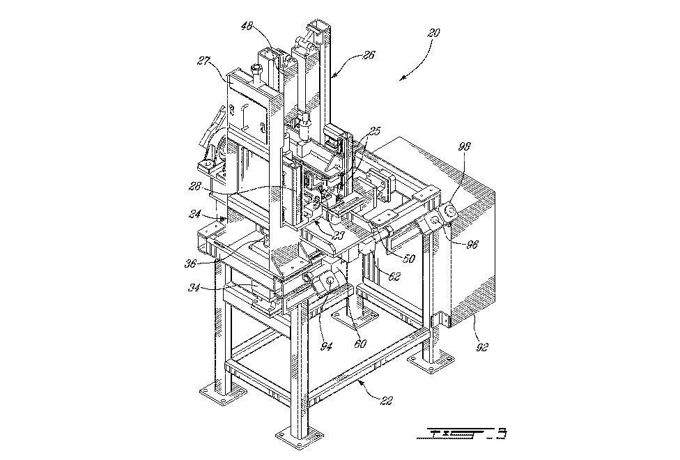
[0024] Turning now to Figures 3 to 6 of the appended drawings, a
head-forming machine 20 will be described. As will become more apparent
upon reading the following description, the head-forming machine 20 allows
receiving and transforming a wire coil having one or many turns of wire.
[0025] The head-forming machine 20 comprises first and second leg
grippers 23 and 25, respectively mounted to a frame 22 via first and second
mounting assemblies 24 and 26. The first and second leg grippers 23 and 25
include respective first and second leg-receiving mechanisms 38 and 74 and
respective first and leg-restraining mechanisms 40 and 76.
CA 03002427 2018-04-18
WO 2017/070770
PCT/CA2015/051087
6
[0026] The first mounting assembly 24 includes a fixed portion 27
fixedly secured to the frame 22 and a movable portion 28 slidably mounted to
the fixed portion 27 via corresponding sliding elements 30 and 32 (see
Figure 5).
[0027] As can be better seen from Figure 3, the movements
between the fixed portion 27 and the movable portion 28 are actuated by a
cylinder 34 mounted to the frame 22 and provided with a piston 36 connected
to the movable portion 28. It is to be noted that an adjustable stop 37 (see
Figure 5) limits the range of translation of the movable portion 28 with
respect
to the fixed portion 27.
[0028] As will now become more apparent, separating the leg
support in the two leg grippers 23 and 25, and slidably mounting the movable
portion 28 to the fixed portion 27, allow the relative movements of the two
leg
grippers 23 and 25 along a first direction. Moreover, as will be described
hereinbelow in more detail, positioning head-forming elements along the path
of the wire coil heads 12-14 during movement thereof will allow applying
controlled deformation thereto.
[0029] With references to Figures 4 and 5, the first leg-receiving
mechanism 38 is fixedly mounted to the movable portion 28 of the first
assembly 24 and the movable first leg-restraining mechanism 40 is slidably
mounted to the movable portion 28 via corresponding sliding elements 42
and 44. A piston 46 of a cylinder 48 interconnects the first leg-restraining
mechanism 40 to the movable portion 28 to selectively actuate the movements
of the first leg-restraining mechanism 40. The first leg-restraining
mechanism 40 is mounted to the movable portion for reciprocating movement
between a resting position and a restraining position, by which it prevents
the
CA 03002427 2018-04-18
WO 2017/070770
PCT/CA2015/051087
7
first leg 16 from moving in the first leg-receiving mechanism 38. The leg-
receiving mechanism 38 and the leg-restraining mechanism 40 will be
discussed in greater details hereinbelow.
[0030] With reference now to Figure 4 of the appended drawings,
the second mounting assembly 26 includes a supporting table 54, which is
slidably mounted to the frame 22 via corresponding sliding elements 50 and 52.
A cylinder 58, provided with a piston 56, also interconnects the frame 22 and
the table 54 to selectively actuate the sliding movements of the table 54 with
respect to the frame 22. As is better seen from Figure 5 of the appended
drawings, two adjustable stops 60 and 62 limit the course of the table 54. As
will be described hereinbelow in more detail, the sliding movement of the
table 54 allows the relative movement of the two symmetrical leg grippers 23
and 25 along a second direction.
[0031] A pivoting sub-assembly 72, which includes the second leg
gripper 25, pivotally mounts the table 54 to the frame 22, thereby extending
the
range of movements between the first and second leg grippers 23 and 25.
More specifically, the pivoting sub-assembly 72 is mounted to the table 54 via
a
shaft 68 secured to the table 54 via two pillow blocks 64 and 66. The shaft 68
defines a pivot axis 70.
[0032] The second leg support 74 is fixedly mounted to the pivoting
sub-assembly 72 and the movable second leg-restraining mechanism 76 is
slidably mounted thereto via corresponding sliding elements 78 and 80. A
cylinder 82 provided with a piston 84 actuates the movements of the second
leg-restraining mechanism 76 with respect to the second leg support 74.
CA 03002427 2018-04-18
WO 2017/070770
PCT/CA2015/051087
8
[0033] As can be better seen from Figure 4, an arm 86 is mounted to
the end of the shaft 68 and is connected to the piston 88 of a cylinder 90 to
thereby interconnect the arm 86 to the table 54. Accordingly, the cylinder 90
actuates the pivoting movement of the shaft 68 about the axis 70.
[0034] A controller 92 is operatively connected to the various
actuators of the machine 20 to control their operation. Furthermore, for
safety
reasons, two distanced start buttons 94 and 96 are provided to start the
machine 20. An emergency stop button 98 is also provided.
[0035] One skilled in the art will understand that the cylinders and
pistons described hereinabove may be pneumatic or hydraulic. Also, other
types of actuators can be used to actuate the mobile parts of the machine 20,
including without limitations motors, belts and pulleys, etc.
[0036] Figures 7 and 8 illustrate in greater details the coil
contacting
portions of the first and second leg-receiving mechanisms 38 and 74 and of the
first and second leg-restraining mechanisms 40 and 76.
[0037] The first leg-receiving mechanism 38 includes a support plate
100 provided with apertures 102, designed to secure the support plate 100 to
the first assembly 24, and smaller apertures 104 allowing elements to be
mounted to the support plate 100.
[0038] A flaring U-shaped bracket 106, configured and sized to
receive the first leg 16 of the coil 10, is mounted to the support plate 100
via
fasteners (not shown) secured to the apertures 104. The bracket 106 includes
an inner wall 110 and an outer wall 112. The distance between the inner and
CA 03002427 2018-04-18
WO 2017/070770
PCT/CA2015/051087
9
outer walls 110 and 112 is such that the first leg 16 may be received therein
in
a snugly fit manner.
[0039] The length and width of the bracket 106 is adapted to the
length and width of the leg 16. The top portion of the bracket 106 is also
flared
to ease the insertion of the first leg 16.
[0040] The first leg-restraining element 40 includes an elongated
wall 41 that is configured and sized for insertion between the inner and outer
walls 110 and 112 of the bracket 106 so as to contact the first leg 16 of the
coil 10 therein. The wall 41 is integral and perpendicular to a first
intermediary
support plate 134 that includes apertures 136 that allows securing the
intermediary support plate 134 to the movable portion 28 via a mounting plate
138 using fasteners (not shown).
[0041] As will be described hereinbelow in more detail by way of
reference to the operation of the machine 20, the wall 41 prevents adverse
movements of the first leg 16 of the coil 10 during forming of its heads 12-14
by
selectively restraining the leg 16 into the leg-receiving mechanism 38.
[0042] The first leg gripper 23 further includes first and second
head-
forming elements 114 and 116, each secured to a respective raised portion
118-120 of the support plate 100. The raised portions 118 and 120 are
positioned adjacent a respective longitudinal end of the U-shaped bracket 106.
[0043] According to another embodiment (not shown), the raised
portions 118 and 120 are omitted and the first and second head-forming
elements 114 and 116 are configured and sized to yield the configuration and
size of the combined elements they replace.
CA 03002427 2018-04-18
WO 2017/070770
PCT/CA2015/051087
[0044] The first leg gripper 23 also includes third and fourth head-
forming elements 124 and 125, which are secured to the mounting plate 138 so
as to be adjacent a respective longitudinal end of the wall 41. The elements
124 and 125 are further configured and sized to cooperate with the respective
first and second head-forming elements 114 and 116 to restrain the movement
and impart a predetermined form to a selected portion of the coil head 12 when
the gripper 23 is closed onto the leg 16 of the coil 10.
[0045] More specifically, the first head-forming element 114 includes
a groove 121 and the third forming element 124 includes a wall 123 that is
registered with the groove 121 when the first leg gripper 23 is closed. As
will be
described hereinbelow in more detail, this arrangement allows immobilizing a
selected part of the coil head 12 during one of the head-forming steps.
[0046] Moreover, each of the cooperating pairs of first and third
head-forming elements 114 and 124 and second and fourth head-forming
elements 116 and 125 defines a support flange against which a first half of
the
coil head 12 is pressed to cause a first controlled deformation thereof during
relative movement of the first and second leg grippers 23 and 25. The fourth
head-forming element 125 further includes a small triangular shape projection
129 defining an edge that extends downwardly from the element 125. As will
become more apparent hereinbelow, the projection 129 defines a low contact
front.
[0047] The second leg-receiving mechanism 74 includes a support
plate 126 and a flaring U-shaped bracket 128 mounted to the support
plate 126. The bracket 128 includes an inner wall 141 and an outer wall 143.
The top portion of the bracket 128 flares to facilitate the insertion of the
second
leg 18 and to cause the movement of the leg-receiving mechanism 74 as will
CA 03002427 2018-04-18
WO 2017/070770
PCT/CA2015/051087
11
be described hereinbelow. It is to be noted that the U-shaped bracket 128 is
taller than the U-shaped bracket 106 of the first leg-receiving mechanism 38.
As will be described hereinbelow in more detail, the two brackets are
positioned
and sized so that when their top openings are registered, the bottom of the
bracket 128 is deeper than the bottom of the other bracket 106.
[0048] As can be better seen from Figure 8, the second leg-
restraining mechanism 76 also includes an elongated wall 77 that is configured
and sized for insertion in the U-shaped bracket 128. The wall 77 is integral
and
perpendicular to an intermediary support plate 140 that includes apertures 142
that allows securing the intermediary support plate 140 to the mounting plate
135 using fasteners (not shown).
[0049] As will be described hereinbelow in more detail, the wall 77
allows preventing adverse movement of the second leg 18 of the coil 10 during
forming of its heads 12-14 by selectively restraining the leg 18 into the
second
leg-receiving mechanism 74.
[0050] Anyone or both of the first and second leg-restraining
mechanisms 40 and 76 can have other adequate forms for this function.
[0051] Turning briefly to figure 9 of the appended drawings, the
second leg-restraining mechanism 76 is so mounted to the end of the piston 84
that it may move laterally onto corresponding sliding elements (not shown). A
spring loaded return mechanism 81 ensures that the mechanism 76 returns to
the position illustrated in Figure 9 when not in use.
[0052] The second leg-receiving mechanism 74 further includes fifth
head-forming element 132 that is mounted to the support plate 126 so as to be
CA 03002427 2018-04-18
WO 2017/070770
PCT/CA2015/051087
12
adjacent one longitudinal end of the U-shaped bracket 106. The element 132
includes a groove 127 that acts as coil wire guide and restrainer.
[0053] The support plate 126 is further provided with two parallel
and
distanced rectangular wedge portions 130 that extends from the main
rectangular portion of the plate 126 on a side thereof, the reason of which
will
be described hereinbelow.
[0054] The second leg gripper 25 further includes sixth and seventh
head-forming elements 154 and 156 mounted to the plate 135 at opposite ends
of the wall 77. Each of the head-forming elements 154-156 includes a
respective protruding wall 158-160 that is provided with a notch 162. Each
notch 162 defines a coil wire guide when the second leg gripper 25 is closed
and the distal edges of the protruding walls 158 and 160 contact the support
plate 126. The sixth head-forming element 154 is configured and positioned to
cooperate with the fifth head-forming element 132 when the second leg gripper
25 is closed onto the second leg 18.
[0055] The shape, size, position and number of the head-forming
elements 114, 116, 124, 125, 132, 154 and 156 are configured to cause
predetermined deformations of the coil heads 12 and 14 upon actuating the
first
and second leg grippers 25 and/or 23 and the first and second mounting
assemblies 24 and 26.
[0056] According to the first illustrative embodiment, the head-
forming elements 114, 116, 124, 125, 132, 154 and 156 are removably
mounted to a respective support 100, 126, 134 and 140 via fasteners. This
allows adapting the machine 10 to other predetermined formation and/or
differently shaped coil. According to another embodiment (not shown), the
CA 03002427 2018-04-18
WO 2017/070770
PCT/CA2015/051087
13
head-forming elements are secured to the support plates adjacent the U-
shaped brackets 106 and 128 using other fastening means such as welding.
[0057] According to still another embodiment (not shown), the first
and second leg supports leg-receiving mechanisms 38 and 74 and first and
second leg-restraining mechanisms 40 and 76 are shaped with integral head-
forming elements.
[0058] Other mechanisms or elements than U-shaped brackets can
be used to receive and limit the movements of the wire coil legs.
[0059] Turning now to Figures 9 to 15, the operation of the machine
20 will be described.
[0060] Generally stated, the operation of the machine 20 includes
gripping the two legs 16 and 18 of the coil 10 and moving the legs 16-18
relatively to head-forming elements for contact therebetween to cause the
controlled and predetermined deformation of the heads.
[0061] Figure 9 illustrates the machine 20 immediately after the
unformed coil 10 has been inserted in the flaring U-shaped brackets 106
and 128 of the first and second leg-receiving mechanisms 38 and 74. It is to
be
noted that, at this stage, the first and second leg-restraining mechanisms 40
and 76 are in their resting position wherein the first and second legs 16 and
18
are unrestrained respectively in the first and second leg-receiving mechanisms
38 and 74. Also, in this preliminary position of the machine 20, the top of
the
second leg-receiving mechanism 74 is generally level with the top of the first
leg-receiving mechanism 38. Since the second leg flaring U-shaped
bracket 128 is taller/deeper than the first flaring U-shaped bracket 106, the
CA 03002427 2018-04-18
WO 2017/070770
PCT/CA2015/051087
14
second leg 18, inserted in the second U-shaped bracket is unrestrained when
the first leg 16 is positioned in the first U-shaped bracket 106. The second
leg
18 is also prevented to sit at the bottom 164 of the first U-shaped bracket
106
by the first and second head-forming elements 114 and 116 and rests
suspended therebetween.
[0062] Next, as shown in Figure 10, the first leg-restraining
mechanism 40 is lowered (see arrow 146) under the action of the piston 46,
placing the mechanism 40 in a gripping position. This movement is made
possible via the corresponding sliding elements 42 and 44. As can be seen
from this figure, the projection 129 forces and maintains a precise portion of
the
first leg 16 onto the second head-forming element 116. At the other end of the
coil 10, the low contact wall 123 forces and maintain another portion of the
first
end 16 onto the head-forming element 114. In the same continuous downward
movement, the wall 41 goes between walls 110 and 112 of the first U-shaped
bracket 106, and abuts the first leg 16 to thereby force and maintain the
first
leg 16 at the bottom 164 of the first leg-receiving mechanism 38, causing
first
controlled deformation of the coil 10.
[0063] As can be seen in Figure 10, the second leg 18 being
unrestrained by the second leg-restraining mechanism 76 when the first
restraining mechanism 40 is moved towards the first leg-restraining
mechanism 38, the above-described first deformations of the coil 10 does not
cause any uncontrolled deformation to the coil 10.
[0064] In the next step, illustrated in Figure 11, the second leg-
restraining mechanism 76 is lowered (see arrow 148) under the action of the
piston 84. This movement is made possible via the corresponding sliding
elements 78 and 80. As can be seen from this Figure, the second leg 18 abuts
CA 03002427 2018-04-18
WO 2017/070770
PCT/CA2015/051087
the inner wall 141 of the flaring U-shaped bracket 128. It will be understood
that further downward movement of the leg-restraining mechanism 76 causes
lateral movement of the second leg-receiving mechanism 74 towards the first
leg-receiving mechanism 38, as illustrated by arrow 150, thanks to the contact
between the second leg 18 and the inner wall 141. Accordingly, the alignment
between the second leg 18 and the flaring U-shaped bracket 128 is not
critical.
[0065] We can also see in Figure 11 that the coil head 14 is received
in the notch 162 of the protruding wall 160. The same is true for the
protruding
wall 158 (not shown).
[0066] Figure 12 shows the further downward movement of the
mechanism 76 (see arrow 148) until it reaches its gripping position. The
contact between the coil heads and the notches 162 and the other head-
forming elements causes controlled deformation of the coil head. It is to be
noted that the second leg-receiving mechanism 74 is kept free to move towards
the first leg-receiving mechanism 38 (see arrow 150) during the downward
movement of the leg-restraining mechanism 76. As mentioned hereinabove,
this movement is caused by the contact between the second leg 18 and the
inner wall 141. This free movement ensures that there is no undesired
deformation of the heads leading to a coil similar to the coil of the prior
art (see
Figure 1). Indeed, by allowing the free movement of the second leg-receiving
mechanism 74 during the movement of the leg-restraining mechanism 76, the
distance between the legs 16 and 18 is changed according to the deformation
of the heads, which prevents uncontrolled deformation as the one shown in the
prior art of Figure 1.
[0067] A portion of the leg-restraining mechanism 76 including the
second wall 77 is shown in dashed lines in Figure 12 to illustrate an
CA 03002427 2018-04-18
WO 2017/070770
PCT/CA2015/051087
16
intermediate state of the leg restraining mechanism 76. In this intermediate
state, the second wall 77 contacts the outer wall 143 of the U-shaped bracket
128 to thereby cause a lateral movement of the leg-restraining mechanism 76
(see arrow 152). One can note the elongation of the spring-loaded return
mechanism 81. Accordingly, the alignment between the second leg-restraining
mechanism 76 and the flaring U-shaped bracket 128 is not critical.
[0068] The downward movement of the second leg-restraining
mechanism 76 continues until the second leg 18 abuts the bottom of the flaring
U-shaped bracket 128 and is restrained by the second wall 77 therein. At this
point, which is illustrated in Figure 13, the transversal position of the
second leg
gripper 25 is locked by a mechanical stopping assembly 165 including a
cylinder 166, a piston 167 and a wedge head 168. Accordingly, when the
cylinder 166 is actuated, the piston 167 extends (see arrow 131) and forces
the
contact between the head 168 and the wedge portion 130 of the plate 126,
thereby preventing further movements of the plate 126 and of the elements of
the second leg gripper mounted thereto.
[0069] With reference to Figure 14, the second assembly 26 is then
pivoted with respect to the first assembly 24 (see arrow 170) under the action
of the piston 88 of the cylinder 90 acting on the shaft 68 (see Figure 4).
This
actuated movement of the second assembly 26 causes further controlled
deformation of the heads 12 and 14 of the coil 10. Indeed, since the legs 16
and 18 are firmly secured between the receiving and restraining assemblies
38, 40, 74 and 76, the pivoting action causes the heads 12 and 14 to be
deformed by their further contact with the first, sixth and seventh head-
forming
element 114, 154 and 156 (see Figures 7 and 8). As can also be seen from
Figure 14, the movement along the direction of arrow 170 causes the heads 12
and 14 to deform according to a wave-shape. Furthermore, this pivoting
CA 03002427 2018-04-18
WO 2017/070770
PCT/CA2015/051087
17
movement ensures that the legs 16 and 18 of the coil will conform to the angle
of the slots of the stator (not shown) that will receive the legs.
[0070] The last step in the deformation of the coil 10 is illustrated
in
Figure 15. This last step includes the actuated movement of the second
assembly 26 towards the first assembly 24 (see arrow 172). This movement is
actuated by the piston 56 of the cylinder 58 (see Figure 4). It is to be noted
that
the amplitude of the sliding movement of the second assembly 26 (see
arrow 174) is limited by the adjustable stop 60 (see Figure 3). As can be seen
from Figure 15, the movement along the direction of arrow 172 causes the
heads 12 and 14 to deform so that the distance between the legs 16 and 18 is
the adequate distance for the insertion into the slots of the stator (not
shown).
This deformation gives the heads 12 and 14 their final shape illustrated in
Figure 16.
[0071] To remove the resulting formed coil 180 from the machine 20,
the leg-restraining mechanisms 40 and 76 are returned to their original
position.
The formed coil 180 may then be removed from the leg-receiving
mechanisms 38 and 74.
[0072] As can be seen in Figure 17, the heads 12 and 14 of the
formed coil 180 are more precisely defined than the formed head from the prior
art and the straight portions of the legs 16 and 18 are longer than the
corresponding straight portions shown in the coil of the prior art (see Figure
1).
[0073] It is to be noted that the distances and angles of movement of
the various elements of the machine 20 have been illustrated herein as
examples only and are adjustable by the controller 92 and/or the various
CA 03002427 2018-04-18
WO 2017/070770
PCT/CA2015/051087
18
adjustable stops. Furthermore, the elements of the machine could be resized
as required by larger or smaller coils.
[0074] The head-forming elements can have other shapes and
configurations than those illustrated so as to impart other forms to the heads
12
and 14. Moreover, different head-forming elements can be used for different
portions of the heads 12 and 14.
[0075] It is believed to be within the reach of a person skilled in
the
art to modify the machine 20 to allow for other or additional relative
movements
between head-forming elements 114, 116, 124, 125, 127, 154 and 156 and the
heads 12 and 14 via the first and second leg support mechanisms 23 and 25.
[0076] The first and second leg supports 23 and 25 can take other
form than those illustrated allowing receiving and restraining the legs 16
and 18.
[0077] Even though some elements of the machine 20 have been
illustrated fastened using fasteners, other fastening means can be used
including welding, clipping, etc.
[0078] A machine for forming the heads of a semi-rigid wire coil is
not limited to rectangular wires and can be used to form heads of semi-rigid
wire coil formed from any wire having a cross section characterized by having
two parallel faces.
[0079] Although the machine for shaping rectangular wire coil heads
and method therefor have been described hereinabove by way of illustrated
CA 03002427 2018-04-18
WO 2017/070770
PCT/CA2015/051087
19
embodiments thereof, it can be modified. It is therefore to be understood that
numerous modifications may be made to the illustrative embodiments and that
the scope of the claims should not be limited by the preferred embodiment, but
should be given the broadest interpretation consistent with the description as
a
whole.