Note: Descriptions are shown in the official language in which they were submitted.
CA 03002763 2018-04-19
WO 2017/070473
PCT/US2016/058125
LASER BEAM CALIBRATION AND BEAM QUALITY MEASUREMENT IN
LASER SURGERY SYSTEMS
CROSS-REFERENCE
[0001] This application claims the benefit under 35 U.S.C. 119(e) of U.S.
Provisional
Patent Application No. 62/244,507, filed October 21, 2015, the full
disclosures of which are
incorporated herein by reference.
FIELD OF THE INVENTION
[0002] Embodiments of the present invention relate to laser eye
surgery systems, and
more particularly, to laser beam calibration and laser beam quality
measurement in laser surgical
systems for eye surgery.
BACKGROUND OF THE INVENTION
[0003] Vision impairments such as myopia (near-sightedness),
hyperopia (far-
sightedness) and astigmatism can be corrected using eyeglasses or contact
lenses. Alternatively,
the cornea of the eye can be reshaped surgically to provide the needed optical
correction. Eye
surgery has become commonplace with some patients pursuing it as an elective
procedure to
avoid using contact lenses or glasses to correct refractive problems, and
others pursuing it to
correct adverse conditions such as cataracts.
[0004] With recent developments in laser technology, laser surgery is
becoming the
technique of choice for ophthalmic procedures. The reason eye surgeons prefer
a surgical laser
beam over manual tools like microkeratomes and forceps is that the laser beam
can be focused
precisely on extremely small amounts of ocular tissue, thereby enhancing
accuracy and
--------------4230.1
CA 03002763 2018-04-19
WO 2017/070473
PCT/US2016/058125
reliability of the procedure. These in turn enable better wound healing and
recovery following
surgery.
[0005] Different laser eye surgical systems use different types of
laser beams for the
various procedures and indications. These include, for instance, ultraviolet
lasers, infrared
lasers, and near-infrared, ultra-short pulsed lasers. Ultra-short pulsed
lasers emit radiation with
pulse durations as short as 10 femtoseconds and as long as 3 nanoseconds, and
a wavelength
between 300 nm and 3000 nm. Examples of laser systems that provide ultra-short
pulsed laser
beams include the Abbott Medical Optics iFS Advanced Femtosecond Laser, the
IntraLase FS
Laser, and the CATALYS Precision Laser System.
[0006] In laser systems for eye surgery, the quality of the laser beam is
determined by
how well the beam can be focused to a specific point, i.e., a circular area
having a diameter
typically of 1-2 microns, which is directly related to how well the beam can
incise or ablate
tissue. But, over time, the laser beam may fail to meet quality specifications
due to optics
misalignment, obscuration, or other failure modes. In this case, continued use
of the laser system
may result in cutting and ablation which is incomplete or degraded. Laser
systems are therefore
frequently tested to verify the beam quality. With many laser surgery systems,
a beam quality
test is performed every single day, well before the first patient is treated.
A well-known beam
quality test is performed by using the focused laser beam to make cuts in a
test sample, such as a
plastic sphere. The cuts are then inspected under magnification, and the beam
quality is inferred
.. from the characteristics of the cuts, such as the positions and the
completeness of the cuts in the
plastic sphere.
[0007] While this sample cutting technique may be relatively easily
performed, it has
several disadvantages. Initially, determining beam quality by inspecting cuts
in a test sample is
- 2 -
CA 03002763 2018-04-19
WO 2017/070473
PCT/US2016/058125
subjective and depends largely on the judgment of the inspector, typically an
eye surgeon in a
surgical facility, and not a laser system technician who may have better
knowledge of the laser
system. The sample cutting test is also an indirect qualitative measurement,
rather than a direct
quantitative measurement. In addition, no diagnostic information is provided
when the inspector
determines the system has failed the test. The sample cutting test also
provides little or no
information on changes in beam quality over time, which information may be
useful in
predicting an impending failure, or evaluating the cause of a failure.
[0008] Other techniques for measuring laser beam quality, such as the
so-called bubble
threshold test, have also been used, with varying degrees of success. But,
these types of tests
require more extensive equipment, time, and expertise. Thus, although these
tests are useful in
laboratory or factory settings, they are not well suited for daily use by an
eye surgeon in a
surgical facility. Consequently, engineering challenges remain in measuring
laser beam quality
in laser eye surgery systems.
[0009] In many laser eye surgery systems, the laser beam is directed
via a scanning
mirror. Position sensors associated with the scanning mirror can sense the
position of the
scanning mirror. If the laser eye surgery system is not properly calibrated,
however, the actual
position of the laser beam on or in the treatment volume of the eye may not
correspond
sufficiently precisely with the position information from the position
sensors. As a result,
engineering challenges also remain in designing improved techniques for
calibrating laser eye
surgery systems.
[0010] Therefore, there is a need for new and improved methods for
measuring beam
quality in laser eye surgery systems.
- 3 -
CA 03002763 2018-04-19
WO 2017/070473
PCT/US2016/058125
SUMMARY OF THE INVENTION
[0011] Hence, to obviate one or more problems due to limitations and
disadvantages of
the related art, this disclosure provides embodiments including methods and
apparatus for
measuring laser beam quality in a laser eye surgery system.
[0012] In a first aspect, methods for measuring beam quality in a laser eye
surgery
system provide a direct, quantitative quality measurement of the focused laser
beam. The
present methods may be automated or computer controlled, allowing them to be
performed very
quickly, and optionally, without the need of major test equipment or testing
expertise.
[0013] In another aspect, a laser eye surgery system includes a
computer which scans a
focused laser beam over a reticle or target and determines beam quality via
laser light reflected
from the target. The target may have a grid pattern of lines, with the
diameter of the focused
laser beam determined based on a time interval for the scanned beam to move
onto a line of the
grid pattern.
[0014] In a further aspect, the beam in the laser eye surgery system
may be calibrated
using scanning mirror position information together with signals from laser
light reflected from
the target.
[0015] This summary and the following detailed description are merely
exemplary,
illustrative, and explanatory, and are not intended to limit, but to provide
further explanation of
the invention as claimed. Additional features and advantages of the invention
will be set forth in
the descriptions that follow, and in part will be apparent from the
description, or may be learned
by practice of the invention. The objectives and other advantages of the
invention will be
realized and attained by the structure particularly pointed out in the written
description, claims
and the appended drawings.
- 4 -
CA 03002763 2018-04-19
WO 2017/070473
PCT/US2016/058125
BRIEF DESCRIPTION OF THE DRAWINGS
[0016] The novel features of the invention are set forth with
particularity in the appended
claims. A better understanding of the features and advantages will be
facilitated by referring to
.. the following detailed description that sets forth illustrative embodiments
using principles of the
invention, as well as to the accompanying drawings, in which like numerals
refer to like parts
throughout the different views. Like parts, however, do not always have like
reference numerals.
Further, the drawings are not drawn to scale, and emphasis has instead been
placed on
illustrating the principles of the invention. All illustrations are intended
to convey concepts,
where relative sizes, shapes, and other detailed attributes may be illustrated
schematically rather
than depicted literally or precisely.
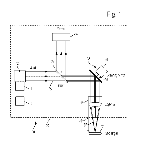
[0017] Fig. 1 is a schematic diagram of a laser eye surgery system.
[0018] Fig. 2 is a side view of beam quality target supported on the
objective lens of the
system of Fig. 1.
[0019] Fig. 3 is a plan view of the target shown in Fig. 2.
DETAILED DESCRIPTION OF THE DRAWINGS
[0020] Embodiments of this invention are generally directed to
systems for laser-assisted
eye surgery, and more particularly, to systems and methods for measuring and
calibrating the
beam quality in a laser eye surgery system.
[0021] As shown in Fig. 1, a laser eye surgery system 10 includes a
laser assembly 12
which generates an unfocused laser beam 18. The laser assembly 12 and a
display 16 are
connected to a computer 14 which controls the operation of the laser assembly
12. The laser
- 5 -
CA 03002763 2018-04-19
WO 2017/070473
PCT/US2016/058125
beam 18 projects out from the laser assembly 12, through the back side of a
sensor mirror 22,
and is reflected via a scanning mirror 28 to an objective lens 30, as
described in detail for
example in US Patent Application No. 14/576,593, titled Confocal Laser Eye
Surgery System,
filed December 19, 2014; US Patent Application No. 14/666,743, titled
Automated Calibration
of Laser System and Tomography System with Fluorescent Imaging of Scan
Pattern, filed March
24, 2015; and US Patent Application No. 14/191,095, titled Laser Eye Surgery
System, filed
February 26, 2014, the full disclosures of which are incorporated herein by
reference. A
beamsplitter cube, or surface within a beamsplitter cube, or any other type of
beam splitter with
similar function, may be used in place of the sensor mirror 22.
[0022] In surgical use, the beam 18 is focused via the objective lens 30
and the focused
beam 18F passes through a patient interface (such as a liquid filled suction
cup on the eye) and
into the eye where the focused laser beam cuts or ablates tissue. The laser
assembly 12 may use
a short pulse laser having a very short (e.g., approximately 10-13 to 10-9
seconds) pulse which
delivers micro joules of energy in a small spot size of about 1.5 to 5
microns, providing various
advantages over manual surgery, and over other lasers using longer pulses.
[0023] Referring now also to Figs. 2 and 3, to measure beam quality a
target 50 is
supported at a precise position on a holder 40 and aligned with the objective
lens 30. The target
50 has multiple lines 52 having high contrast with the background field 54 of
the target. The
holder 40 may be attached to the objective lens 30 via quick connect pins 42
or other fittings or
fasteners ordinarily used to attach the patient interface. Alternatively, the
holder 40 may be
attached to the objective lens 30 using dedicated holder fittings, clamps or
fasteners. In either
case the target 50 is precisely located at a known position in three
dimensions relative to the
objective lens 30. The location of the target may also be precisely measured
by a camera system
- 6 -
CA 03002763 2018-04-19
WO 2017/070473
PCT/US2016/058125
integrated into the laser system instead of precisely locating the target by
mechanical means. The
laser assembly, computer, sensor mirror, sensor and scanning mirror may be
entirely contained
within an enclosure 20, with only a portion of the objective lens and the
target outside of the
enclosure.
[0024] When measuring beam quality, the focused laser beam 18F is scanned
in a
trajectory over the target 50. As the beam 18F crosses a line 52 on the
target, a fraction of the
laser light is reflected back to a sensor 24 via the objective lens 30, the
scanning mirror 28 and
the second side of the sensor mirror 22. To provide sufficient reflected or
scattered laser light,
the target 50 may have lines 52 of a reflective material such as chrome,
aluminum, white ink, etc.
.. on a transparent substrate such as glass, or on a non-reflective opaque
substrate. The target may
also be constructed so that the lines are transparent or non-reflecting or low-
reflecting, and the
background is reflective. The lines have precise straight edges. If the
substrate is transparent, the
sensor 24 may optionally be positioned below the target, i.e., with the target
50 between the
objective lens 30 and sensor 24.
[0030] Referring to Fig. 3, the line width is advantageously several times
greater than the
beam diameter, so that the line completely reflects or blocks the beam as the
beam crosses the
line 52. In the example shown, the line width is 0.2 mm (100-200 times the
nominal beam
diameter) with 1 mm X 1 mm grid spacing. A target having slits or non-
reflective lines on a
reflective background may also be used. The beam diameter as used here means
the width or
dimension of the beam in a particular direction of scan, and not necessarily
strict circular
symmetry.
[0031] The target 50 at a location at a fixed distance from the
objective lens 30 only
fully characterizes the beam at that location, allowing for evaluation of a
two dimensional
- 7 -
CA 03002763 2018-04-19
WO 2017/070473
PCT/US2016/058125
plane. To evaluate the beam in three dimensions, the target 50 may be placed
at various distances
from the objective lens. For example, two or more targets 50 may be placed at
different vertical
positions relative to the objective lens 30, with beam quality measured with
the beam focused
initially on the first target and then on the second target. The target may
optionally be provided
in an optical element, such as a prism that may be temporarily move into the
beam path to
measure beam quality and then returned to a storage position not in the beam
path. The target 50
may also be on a stage which is movable in the Z-axis. In this case, by
comparing measurements
made at different Z-axis dimensions, the position of the focal plane (where
the beam is best
focused) may be identified.
[0032] The scanning mirror 28 may include a Z-scan device 58 and an XY-scan
device
60. The Z-scan device 58 may be used to vary a convergence/divergence angle of
the beam 18
and thereby change a location of the focal point in the Z direction, i.e., the
direction of
propagation of the beam 28, for example by using movable lenses.
Alternatively, the objective
lens 30 is moved in the Z-direction to focus the beam in the Z direction via
an actuator such as a
voice coil. The XY-scan device 60 deflects the beam 28 in the X and Y
dimensions transverse to
the Z direction by deflecting one or more mirrors.
[0033] Some laser eye surgery systems include a sensor 24 as part of
a confocal detection
assembly. In these systems, laser light reflected from the eye during surgery
is detected by the
confocal detection assembly to generate a reflected light intensity signal.
This signal is coupled
with beam scanning position information and processed in a computer to image
or locate
structures of the eye. Consequently, in systems having a sensor 24 included in
a confocal
detection assembly, during beam quality measuring, the sensor of the confocal
detection
assembly may be used to generate an intensity signal indicative of the
intensity of the sensed
- 8 -
CA 03002763 2018-04-19
WO 2017/070473
PCT/US2016/058125
laser light reflected from the target, rather than from the eye. In this case,
no separate additional
sensor is needed.
[0034] The quality of the focused beam 18F, i.e., the minimum focused
beam size, may
be measured by scanning the beam over the target 50, with the target
positioned relative to the
objective lens 30 so that the grid lines 52 are in the plane of focus. Laser
light reflected by the
grid lines 52 is detected and analyzed, providing a measurement of the cross
section of the beam
18F. As the beam 18F moves across a grid line 52, the detected signal
corresponding to the
reflected laser light will show a very steep rise if the beam 18F is well
focused. Although beam
shape is also an aspect of beam quality, changes in beam shape will also
change the measured
beam width in one direction or another. Measuring the beam width in one or two
directions will
reveal the beam quality in virtually all practical cases.
[0035] The measurement process may be performed via the following
steps:
1. Determining a Trajectory
[0036] Determine a trajectory for scanning the laser beam over the
target. The
parameters used in calculating the trajectory include the grid line positions,
the angle of the beam
scan across the lines, and the length of the scan across each line. The scan
trajectory of the beam
18F may be selected so that the beam crosses a grid line 52 in two orthogonal
directions. This
trajectory results in the short pulse signals. As short pulse signals may be
more challenging to
resolve, longer pulse signals may be generated by scanning the beam at a low
angle (e.g., 5-30
degrees) to the grid line, allowing for higher resolution of the signals via
the sensor 24 and the
computer 14.
[0037] In a basic form, the scan trajectory may be a raster style
scan starting at one
corner of the target and scanning from in sequential or alternating horizontal
rows down to the
- 9 -
CA 03002763 2018-04-19
WO 2017/070473
PCT/US2016/058125
opposite corner of the target, followed by vertical scanning of columns. Many
other types of
trajectories, including circular, spiral, and interrupted or segmented
trajectories, may be used. Of
course, since the scan angle (the angle at which the beam scans over the line)
is a factor in
measuring beam quality, orthogonal straight line trajectories may be easiest
to use.
2. Scanning the Focused Beam
[0038] Scan the focused beam in the selected trajectory over the
target via movement of
the scanning mirror 28 in two dimensions. The sensor 24 senses the reflected
or scattered laser
light and provides a corresponding output signal to the computer 14. The
computer 14 or other
circuitry converts the sensor output signal into a digital signal which is
stored and analyzed by
the computer 14. The beam 18F is aimed via the mirror 28 over a range of X-
axis and Y-axis
movement. The beam is typically moved in incremental steps. With a step size
of e.g., 1 micron,
and a beam diameter of 1.5 microns, the detected signal changes from zero to a
maximum in 1-2
steps. In the example shown, a full range of X or Y axis movement over e.g. 25
mm may be 150
steps.
[0039] Laser eye surgery systems 10 are generally designed to perform
surgery within a
volume or space of the eye, known as the treatment volume, which in a selected
focal plane or Z-
axis dimension, is approximately the diameter of an adult human cornea,
usually about 16 mm.
The beam 18F may be used to perform surgery at all positions within the
treatment volume.
Consequently, it is desirable to be able to measure beam quality at all
positions within the
treatment volume. By moving the beam in a trajectory across an e.g., 22-28 mm
square grid, as
shown in Fig. 3, beam quality can be measured at all positions within the
treatment volume in
most or all laser eye surgery systems.
-10-
CA 03002763 2018-04-19
WO 2017/070473
PCT/US2016/058125
[0040] As the beam 18F moves away from the center position, beam
quality tends to
degrade (i.e., beam diameter increases or becomes elliptical or asymmetric)
due to the
characteristics of the optical components used to aim and focus the beam.
Consequently, an
accurate assessment of beam quality involves measuring the beam diameter at
all positions
within the treatment volume.
3. Generating a Table
[0041] For each line crossing or coordinate, generate a table of
sensor output versus
beam position. The computer 14 is also connected to the scanning mirror 28
with the scan mirror
angle instantaneously provided to the computer 14. The computer determines the
beam position
on the target 50 based on the scan mirror angle. The beam scanning velocity is
known as it is a
function of the movement of the scanning mirror 28. The sensor output is the
digitized signal
from the sensor, which is a function of sensed reflected light.
4. Determining Beam Width
[0042] For each line crossing, determine the beam diameter from the
data table created in
step 3 above. A variety of algorithms can be used. The algorithm may measure
the time interval
between 10% and 90% of the maximum signal to calculate the beam diameter. The
time interval
for a high quality tightly focused beam having a small diameter is less than
time interval for a
lower quality less focused beam having a larger diameter. Based on the
digitized data from the
sensor 24, the computer 14 calculates an average or representative slope of
the signal. The slope
and beam scanning velocity is proportional to the beam diameter. Specifically,
since the beam
scanning velocity is known, and the slope is a function of the time interval
between the leading
and trailing edges of the beam intersecting the line, the diameter of the beam
may be calculated.
The computer may then display a number indicative of the beam diameter on the
display 16. If
-11-
CA 03002763 2018-04-19
WO 2017/070473
PCT/US2016/058125
the number is within the system specification, the system passes. If not, the
system fails. In this
case, the computer may optionally lock out the system from further use until
the system is
brought into specification, typically adjusting alignment or other parameters
of optical
components of the system.
[0043] This process described above in steps 1-4 can be repeated as the
focus of the laser
beam is adjusted in steps, so that the beam width can be calculated as a
function of focus
position. The best focus position is determined from this analysis by
interpolating the data to
find the minimum beam width position.
[0044] As used here, the term line or grid line includes slits.
Velocity means a speed and
a direction relative to a grid line 52. Intersect means directing the beam
over or onto a line or
other target feature sufficiently to generate the signals used for performing
the calibration and
measurement methods described. Although Fig. 3 shows continuous lines, line
segments may
also be used. Targets having curved lines, such as rings or spirals may
optionally be used with
correspondingly scanning trajectories.
[0045] A method for determining quality of a focused laser beam in a laser
eye surgery
system may be performed by scanning the focused laser beam in a trajectory
over a target having
two or more lines, and determining the position of the focused laser beam on
the target during
the scanning. Laser light reflected or scattered by one of the lines as the
laser crosses the line is
sensed and digitized. A table of digitized sensed laser light values versus
position of the beam is
then generated, and the diameter of the focused laser beam is determined based
on the table. In
this method the target may have a grid of perpendicular lines, with each line
having a width at
least 5 times greater than a diameter of the focused laser beam.
- 1 2 -
CA 03002763 2018-04-19
WO 2017/070473
PCT/US2016/058125
[0046] In addition to the methods described above for measuring beam
quality, and beam
quality within a treatment volume, since measurements are made by sensing the
beam passing
over lines of a known geometry in the treatment volume, methods for
simultaneously calibrating
the scanned beam (or verifying the calibration of the scanned beam) may also
be performed,
.. while measuring the beam quality. Consequently, the methods are useful for
both verifying
targeting and beam quality within the treatment volume. Since the target can
be viewed by an on-
board imaging system (camera, in 2D), the calibration of position and beam
quality may also be
mapped to the camera image, thus calibrating the targeting displayed to the
surgeon operating the
system.
[0047] Calibration may be performed by scanning a focused laser beam in a
trajectory
over the target via a scanning mirror, and sensing laser light reflected or
scattered by a first line
of the target at time Ti when the laser beam intersects a first edge of the
first line to determine an
actual laser beam position. The first edge can be a leading edge or a trailing
edge of the first line
of the target. The position of the scanning mirror is also sensed at time Ti,
for example via
feedback position sensors on the scanning mirror. These steps are repeated
with the laser beam
intersecting subsequent lines at subsequent times. A table of digitized actual
laser beam position
values versus sensed scanning mirror position values can then be generated,
with the calibration
of the achieved based on the table.
[0048] During the calibration and/or beam quality measurement
procedures the target
may be precisely fixed in a known or centered position relative to the
objective lens, so that
actual beam positions on the target can be calibrated back to scanning mirror
positions.
Alternatively, if the target is not precisely centered relative to the
objective lens, pixels on a
-13-
CA 03002763 2018-04-19
WO 2017/070473
PCT/US2016/058125
display may be mapped to actual locations on the target, and an offset
function used to
compensate for an off center position of the target.
[0049] All patents and patent applications cited herein are hereby
incorporated by
reference in their entirety.
[0050] The use of the terms "a" and "an" and "the" and similar referents in
the context of
describing the invention (especially in the context of the following claims)
are to be construed to
cover both the singular and the plural, unless otherwise indicated herein or
clearly contradicted
by context. The terms "comprising," "having," "including," and "containing"
are to be construed
as open-ended terms (i.e., meaning "including, but not limited to,") unless
otherwise noted. The
term "connected" is to be construed as partly or wholly contained within,
attached to, or joined
together, even if there is something intervening. Recitation of ranges of
values herein are merely
intended to serve as a shorthand method of referring individually to each
separate value falling
within the range, unless otherwise indicated herein, and each separate value
is incorporated into
the specification as if it were individually recited herein. All methods
described herein can be
performed in any suitable order unless otherwise indicated herein or otherwise
clearly
contradicted by context. The use of any and all examples, or exemplary
language (e.g., "such
as") provided herein, is intended merely to better illuminate embodiments of
the invention and
does not pose a limitation on the scope of the invention unless otherwise
claimed. No language
in the specification should be construed as indicating any non-claimed element
as essential to the
practice of the invention.
[0051] While certain illustrated embodiments of this disclosure have
been shown and
described in an exemplary form with a certain degree of particularity, those
skilled in the art will
understand that the embodiments are provided by way of example only, and that
various
-14-
CA 03002763 2018-04-19
WO 2017/070473
PCT/US2016/058125
variations can be made without departing from the spirit or scope of the
invention. Thus, it is
intended that this disclosure cover all modifications, alternative
constructions, changes,
substitutions, variations, as well as the combinations and arrangements of
parts, structures, and
steps that come within the spirit and scope of the invention as generally
expressed by the
following claims and their equivalents.
- 1 5 -