Note: Descriptions are shown in the official language in which they were submitted.
EMBOLUS REMOVAL DEVICE WITH BLOOD FLOW RESTRICTION
AND RELATED METHODS
BACKGROUND OF THE INVENTION
2. Field of the Invention
The present invention generally relates to devices and methods useful for clot
retrieval, and removal devices to treat, among other things, ischemic stroke.
3. Description of the Prior Art
Currently, the FDA-approved treatment options for an acute ischemic stroke
include intravenous (IV) delivery of clot dissolving medicine and mechanical
thrombectomy.
For treatment use, clot dissolving medicine, such as the thrombolytic agent
(Tissue Plasminogen Activator (t-PA)), is injected into the vasculature to
dissolve
blood clots that are blocking blood flow to the neurovasculature. Intravenous
t-PA is
currently limited in use because it must be used within a three-hour window
from the
onset of a stroke and can result in an increased risk of bleeding. This
standard of
care leaves room for upgrade, and is only the appropriate approach to
treatment for a
limited class of individuals, groups and temporally-limited exigent cases.
A second option includes the use of mechanical thrombectomy devices. Such
devices are designed to physically capture an embolus or clot, and to remove
it from
the blocked vessel, thereby restoring blood flow. The major advantage of the
mechanical thrombectomy device is it can expand the treatment window from
three
hours to over ten hours.
Some existing mechanical thrombectomy devices used for increasing blood
flow through an obstructed blood vessel include: 1) a filter trap designed and
built to
collect and remove emboli; 2) a cork-screw guidewire-like device to retrieve
embolus;
Date Recue/Date Received 2023-04-13
CA 03002804 2018-04-20
WO 2017/074721 PCT/US2016/057244
and 3) a stent-like device connected to a delivery wire to retrieve embolus.
All of
these devices suffer from certain disadvantages.
First, filter-type thrombectomy devices tend to be cumbersome and difficult to
deliver and deploy, and a larger-profile guide catheter may be needed to fully
remove
the embolus. In addition, it is difficult to coordinate precise and
predictable
movement to position the device properly in the vessel. The device can drift
within
the vessel, twist, or not be adequately conforming to the vessel wall and,
therefore
not effective for removing embolus.
Cork-screw guidewire devices can only capture and remove emboli that are
firm, or subject to certain mechanical variables such as being held together
by itself
as one piece. Cork-screw guidewire devices are not effective in removing
particulate
matter that may be scattered or broken up.
Stent-like mechanical thrombectomy devices are not capable of capturing
small emboli that break off from a large embolus (if any), and can lead to
complications such as the blockage of distal smaller vessels, vessel
dissection,
perforation, and hemorrhage arising as a result of over-manipulation in the
vessel.
The disadvantages common to all of the devices described above include, for
example: 1) the device may capture an embolus, but then lose grasp of it and
migrate/deposit it incidentally into another area of the neurovasculature,
creating the
20 potential for a new stroke in a different part of the neurovasculature;
2) the device is
not capable of capturing small embolus breaking off from the larger embolus
and
preventing it from migrating to a more distal area of the neurovasculature; 3)
the
relative large device profile prevents these devices from treating the distal
smaller
diameter vessels; and 4) risk of sICH (symptomatic Intra-cerebral Hemorrhage)
after
2 5 intra-arterial clot removal in acute stroke patients.
Other flaws in the current mechanical thrombectomy designs include poor
visibility/radiopacity, lack of variation in the delivery portion to enhance
and improve
deliverability, and lack of coatings or modified surface textures on the
treatment
portion to enhance embolus affinity, etc. In conclusion, there is a great need
for
3 improved devices, systems, and methods for restoring blood flow through a
blood
vessel. None of the existing medical mechanical thrombectomy devices address
all
necessary needs to date.
CA 03002804 2018-04-20
WO 2017/074721 PCT/US2016/057244
SUMMARY OF THE DISCLOSURE
The present invention is directed to a method and devices for removing clots,
emboli and other luminal blockages from a blood vessel. A clot removal device
is
provided, having an expandable treatment member having a distal tip and a
proximal
.E end, a delivery wire having a distal end coupled to the proximal end of
the
expandable treatment member, and a flow restrictor carried along the delivery
wire at
a location that is separate and proximal from the expandable treatment member.
The
flow restrictor has a body with a distal section and a proximal section, the
distal
section being covered and the proximal section being uncovered. An access
catheter is delivered to a location proximal to a location of a clot or
embolus in a
blood vessel, and then the clot removal device is delivered through a lumen in
the
access catheter to the location of the clot or embolus in the blood vessel.
The
expandable treatment member is expanded at a location that is at or distal to
the
location of the clot or embolus, and the clot or embolus is caught in, or
engaged with,
the expandable treatment member. The access catheter is then positioned with
respect to the flow restrictor such that the uncovered proximal section is
completely
covered by the distal end of the access catheter and the covered distal
section forms
a seal with the distal end of the access catheter, and then aspiration is
applied
through the access catheter and through the uncovered proximal section to
remove
II the clot or embolus from the blood vessel.
The clot removal device of the present invention can also be used in
accordance with another method, where the clot removal device is delivered to
a
location of a clot or embolus in a blood vessel, the expandable treatment
member is
expanded at a location that is at or distal to the location of the clot or
embolus, the
clot or embolus is caught in, or engaged with, the expandable treatment
member, the
expandable treatment member is withdrawn into the distal section of the flow
restrictor, and the expandable treatment member and the flow restrictor are
withdrawn from the blood vessel.
The devices of the present invention can be made from either metallic
biocompatible material (such as Nitinol, stainless steel, Co--Cr base alloy,
Ta, Ti,
etc.) or polymer based biocompatible material (polymers with shape memory
effect,
PTFE, HDPE, LDPE, Dacron, Polyester, etc.). For ischemic stroke treatment, the
expandable treatment member must be flexible enough to negotiate the torturous
vasculature of the brain and without modifying the vessel profile at the
target location.
CA 03002804 2018-04-20
WO 2017/074721 PCT/US2016/057244
4
The profile of the expandable treatment member must be small enough to reach
target treatment site as known to artisans.
BRIEF DESCRIPTION OF THE DRAWINGS
FIG. 1 is a side view of a fully expanded clot removal device according to a
first embodiment of the present invention.
FIG. 2 is a side view of the clot removal device of FIG. 1 shown in a
compacted orientation inside a microcatheter.
, n FIG. 3A is a side view of the clot removal device of FIGS. 1 and 2
shown with
the expandable treatment member fully pushed outside the microcatheter.
FIG. 3B is a side view of the clot removal device of FIGS. 1 and 2 shown with
the control arms and the expandable treatment member slightly pushed outside
the
microcatheter.
t FIG. 4 is a side view of a fully expanded clot removal device according
to a
second embodiment of the present invention.
FIG. 5 is a side view of the clot removal device of FIG. 4 showing the
collection of a clot in a vessel.
FIG. 6A is a side view of the clot removal device of FIG. 4 showing the clot
22 collected inside the expandable treatment member.
FIG. 6B is a side view of the clot removal device of FIG. 4 showing the clot
collected inside the expandable treatment member, and the expandable treatment
member inside the proximal flow restrictor.
FIG. 7 is a side view of a fully expanded clot removal device according to a
2 5 third embodiment of the present invention shown with a clot caught on
the surface of,
and between the cell spaces, of the expandable treatment member.
FIG. 8 is a side view of the clot removal device of FIG. 7 showing the
expandable treatment member being pulled into the proximal flow restrictor.
FIG. 9 is a side view of the clot removal device of FIG. 7 showing the
30 expandable treatment member inside the proximal flow restrictor.
FIG. 10 is a side view of a fully expanded clot removal device according to a
fourth embodiment of the present invention.
FIG. 11 is a side view of the removal device of FIG. 10 showing the
expandable treatment member being pulled into the proximal flow restrictor
with the
CA 03002804 2018-04-20
WO 2017/074721 PCT/US2016/057244
clot engaged on its outer surface.
FIG. 12 is a side view of the removal device of FIG. 10 showing the
expandable treatment member inside the proximal flow restrictor.
FIG. 13A is an enlarged side view of an exemplary proximal flow restrictor
design.
FIG. 13B is an enlarged side view of an exemplary proximal flow restrictor
design with a push wire connected from the proximal end.
FIG. 130 is an enlarged side view of an exemplary proximal flow restrictor
design with a through lumen on the delivery element from the proximal end.
c FIG. 14A is an exemplary application of the proximal flow restrictor of
FIG. 13B
combined with an access catheter, such as a guide catheter, or other procedure
support catheters (not in aspiration position).
FIG. 14B is an exemplary application of the proximal flow restrictor of FIG.
13B
combined with an access catheter, such as a guide catheter, or other procedure
.. support catheters, in an aspiration position.
FIGS. 15A-150 illustrate another embodiment of the clot removal device
according to the present invention where the expandable treatment member is
omitted.
-0
DETAILED DESCRIPTION OF THE PREFERRED EMBODIMENTS
The following detailed description is of the best presently contemplated modes
of carrying out the invention. This description is not to be taken in a
limiting sense.
but is made merely for the purpose of illustrating general principles of
embodiments
2 5 of the invention. The scope of the invention is best defined by the
appended claims.
The present invention is directed to a device for removing emboli and other
luminal blockages. The device includes an expandable treatment member, such as
a
mesh or a cage, that is associated with a proximal flow restrictor. During
treatment,
the expandable treatment member is positioned within or distal to an embolus
within
30 a blood vessel and then transitioned into an expanded state. In certain
embodiments, the expandable treatment member's normal state is the expanded
configuration, and the expandable treatment member is compacted and delivered
to
the treatment site in the compacted configuration through a delivery sheath or
catheter. The expandable treatment member is deployed from the delivery
sheath,
CA 03002804 2018-04-20
WO 2017/074721 PCT/US2016/057244
which causes it to return to its normal expanded profile by the elastic energy
stored in
the device. Expansion of the expandable treatment member engages the
expandable treatment member with the emboli or clot at the blockage. In
addition,
the proximal flow restrictor can also expand to a larger diameter state when
it is
deployed from the delivery sheath or catheter. Expansion of the proximal flow
restrictor advantageously limits or restricts forward blood flow and creates a
pressure
gradient within the blood vessel between locations distal and proximal to the
flow
restrictor. The pressure gradient helps to prevent the clots from being
flushed away
from the treatment member, thereby assisting in removal of the embolus from
the
blood vessel. Specifically, the pressure difference can act like a vacuum to
assist in
removal of the embolus from the blood vessel. After expansion, the expandable
treatment member and the emboli engaged with the expandable treatment member
are removed from the blood vessel. During clot removal, the expandable
treatment
member (with the blood clot engaged) can also be pulled inside the proximal
flow
1 5 .. restrictor first (i.e., the clot retrieval component with clots engaged
are housed inside
proximal restrictor), and then pulled back into guide catheter, and removed
from the
blood vessel. Furthermore, aspiration/vacuum suction can be applied through
the
lumen of the access catheter lumen and proximal flow restrictor to prevent
clots from
breaking off and flowing downstream.
2 "9 In addition, the proximal flow restrictor regulates the forward blood
flow and
allows the controlled (gradual) restoration of the blood flow, and reduces the
risk of
sICH (symptomatic Intra-cerebral Hemorrhage) after intra-arterial clot removal
in
acute stroke patients.
Devices of the present invention are suitable for removal of blockages in body
.. lumens, and are particularly well-suited for removal of thrombi, emboli, or
atheroma in
the vasculature, including those in arteries and veins. It is understood that
the
dimensions of the device may be modified to suit a particular application. For
example. devices of the invention used for treatment of deep vein thrombosis
may
have a larger cross-section than devices of the invention used for treatment
of brain
ischemia.
Compared with existing mechanical thrombectomy devices, the unique device
design included in this invention has the advantage of providing a proximal
flow
restriction feature to block the forward flow of blood when the device is
deployed
during use. This feature can help to eliminate or reduce the risk of flush, or
the
CA 03002804 2018-04-20
WO 2017/074721 PCT/US2016/057244
7
break-up of the blood clots during the procedure.
Another important advantage provided by the present invention is the central
lumen of the proximal flow restrictor can be used or combined with the lumen
of the
access catheter to apply aspiration/suction force to help with the complete
removal of
the blood clots in the vasculature.
Thus, the device described in the present invention overcomes the
shortcomings of the existing technologies and can be delivered to the target
vasculature smoothly, can be retrieved safely, and can remove the entire
embolus
with fewer passes. In use, the mechanical thrombectomy device described in the
present invention can be compacted to a low profile and loaded onto a delivery
system and delivered to the target location in the vessel by a medical
procedure such
as through use of a delivery catheter. The mechanical thrombectomy device can
be
released from the delivery system when it reaches the target implant site and
expanded to its normal expanded profile by the elastic energy stored in the
device
1 5 .. (self-expandable device).
As for the relative position of the expandable treatment member in relation to
the embolus or blood clot, it can either be deployed at the site of the
embolus, or
deployed distal to the embolus. In dealing with long embolus, the expandable
treatment member can also be used to remove the embolus from the proximal
portion
to the distal portion with multiple passes, until the entire embolus is
removed.
Turning now to the drawings, FIGS. 1-2 illustrate a device 100 for removing
emboli and other luminal blockages according to the present invention. The
device
100 can be made from one piece or multiple pieces of NitinoITM super elastic
material
or Nitinol TM super-elastic alloy tubing. It can also be made from other
biocompatible
25 materials that exhibit super-elastic or shape memory properties. The
device 100 can
be made by laser cutting, mechanical machining, chemical machining,
electrochemical machining, EDM, braiding and related techniques known to those
skilled in the art.
The device 100 has an expandable treatment member 102 carried along a
3D delivery wire 104 adjacent the distal end of the delivery wire 104. The
delivery wire
104 has a soft distal tip 106 that extends distal from the expandable
treatment
member 102, and has a marker coil embedded therein. A plurality of laser cut
control
arms 108 couple the proximal portion of the expandable treatment member 102
with
a hub 110 along the delivery wire 104. Specifically, each control arm 108 has
CA 03002804 2018-04-20
WO 2017/074721 PCT/US2016/057244
8
opposite ends connecting the proximal portion of the expandable treatment
member
102 and the hub 110. A proximal flow restrictor 112 is carried on the delivery
wire
104 proximal to the hub 110. Marker bands or marker coils can be incorporated
into
the proximal flow restrictor 112 and the expandable treatment member 102 for
visibility. At least one end of the proximal flow restrictor 112 can move
freely along
the delivery wire 104.
The expandable treatment member 102 can be configured to act as a catch
basket for the clot or embolus, and in this embodiment is shaped as a cone in
its fully
expanded configuration, with an apex 120 at the distal-most portion of the
0 expandable treatment member 102 secured to the delivery wire 104 adjacent
the
distal tip 106, and with the expandable treatment member 102 increasing
radially in
diameter until reaching its proximal-most ring 122. The expandable treatment
member 102 can be made of a NitinolTM braided mesh and can be shape-set to the
cone shape by a thermal mechanical process. Most significantly, the expandable
1 5 treatment member 102 is not cylindrical in configuration which allows
it to better
conform to the vessel contour and to move more freely inside the vessel. The
size of
the opening for the ring 122 can range from 0.5 mm to 12 mm. The length of the
distal cone portion from the apex 120 to the ring 122 can range from 2 mm to
40 mm.
The meshed frame of the expandable treatment member 102 can be provided
.7: 0 with a plurality of openings. Frame members or struts form the body
of the meshed
frame and define the plurality of openings. In certain embodiments, the frame
members are a plurality of intersecting wires or other threads. The frame
members
may form a mesh or cage-like structure that defines the plurality of openings.
In
certain embodiments, the expandable treatment member 102 can include a
plurality
2 3 of protrusions 150 on the frame. See FIG. 1 The plurality of
protrusions 150 further
engages the embolus for removal.
As an alternative to, or in addition to, the plurality of protrusions 150, the
expandable treatment member 102 may include one or more surface modifications
or
treatments. For example, as explained in greater detail below, the surface of
the
30 .. expandable treatment member 102 may be roughened to improve clot
adhesion.
The main geometrical axis of the expandable treatment member 102 can be offset
or
different from the longitudinal center axis of the native blood vessel. When
the
expandable treatment member 102 is in use, both the delivery catheter (e.g.,
microcatheter 124) and/or the movement axis of the expandable treatment member
CA 03002804 2018-04-20
WO 2017/074721 PCT/US2016/057244
102 can be different from the longitudinal central axis of the vessel, and can
contact
the side wall of the blood vessel.
The delivery wire 104 can be made of super-elastic Nitinol wire, stainless
steel
wire, braided stainless steel wire, Co-Cr alloy and other biocompatible
materials.
E The diameter of the delivery wire 104 can range from 0.008" to 0.030",
and the
delivery wire 104 can have variable diameters/stiffness along its length.
This distal tip 106 can be made of Ta, Pt, W, Pt-W. or Pt-Ir alloys for
radiopacity, and from radiopaque coils or markers.
The control arms 108 can be laser-cut from a super-elastic Nitinol material.
They are preferably taut when the expandable treatment member 102 is in its
full
expanded configuration. The control arms 108 function to control the opening
diameter of the ring 122, so that the largest diameter of the ring 122 can be
achieved
when the control arms 108 are completely pushed out of the sheath of a
microcatheter 124 (see FIG. 2). The diameter of the ring 122 can be adjusted
by the
length of the control arms 108 being pushed out of the microcatheter 124. Even
though the present embodiments are being described as having three control
arms
108, it is possible to provide one, or more than two, control arms 108.
The hub 110 can be made from radiopaque materials, and can move freely
along, and with respect to, the delivery wire 104. The hub 110 can also be
secured
to a fixed location along the delivery wire 104
The proximal flow restrictor 112 can be a bulbous structure and can be made
of a NitinolTM mesh, and it is fixedly connected to the delivery wire 104 at
its proximal
end, while the distal end of the proximal flow restrictor 112 can move freely
along,
and with respect to, the delivery wire 104. In another embodiment, the
proximal flow
restrictor 112 can be fixedly connected to the delivery wire 104 at its distal
end, while
the proximal end of the proximal flow restrictor 112 can move freely along,
and with
respect to, the delivery wire 104. The proximal flow restrictor 112 can have a
first
smaller compacted profile for delivery through the microcatheter 124 possible.
The
proximal flow restrictor 112 can have a second larger expanded
diameter/profile
when released from the microcatheter 124 or other delivery system to block,
limit, or
restrict the blood flow. The bulbous structure can be a braided or laser cut
structure,
and made from a film, membrane, braided or netted material. In certain
embodiments, the proximal flow restrictor 112 is a polymeric film or membrane.
In
other embodiments, the proximal flow restrictor 112 is a braided or woven net
formed
CA 03002804 2018-04-20
WO 2017/074721 PCT/US2016/057244
from a metal, polymer, or combination thereof. The type and material of the
proximal
flow restrictor 212 may be chosen based on the desired coverage (i.e. amount
of flow
to be restricted). The surface of the proximal flow restrictor can be either
entirely or
partially covered by some polymer materials to restrict the blood flow. It can
be
5 fabricated from the one or two element(s) of the device 100, or
fabricated from other
pieces of material, then attached to the delivery wire 104 by mechanical
means, or
via a thermal (laser or soldering) process, or adhesive/glue, or heat shrink
technology. The bulbous structure can also be fabricated from the same piece
of
NitinolTM tubing as that of the device 100 by laser cutting or chemical
processes and
12 then shape-set to a larger diameter than the raw NitinolTM tubing.
The proximal flow restrictor 112 can have a diameter in its fully expanded
configuration that is about the same as the diameter of the opening ring 122
of the
expandable treatment member 102 when the expandable treatment member 102 is
in its fully expanded configuration. The diameter of the proximal flow
restrictor 112
5 can range from 0.5 mm to 12 mm, and its length can range from 2 mm to 60
mm.
Radiopaque markers can be attached on any portion of the device 100 for
positioning. One way to provide full visibility for the device 100 is to run a
radiopaque
material through the entire or partial lumen of the delivery wire 104. Markers
can
also be placed on the expandable treatment member 102 to aid in positioning.
In
addition. radiopaque markers (marker coils, marker bands, radiopaque wire(s),
radiopaque coatings, etc.) can be integrated into the proximal flow restrictor
112.
The device 100 can have a surface treatment on selected portions to improve
performance for the selected portions of the device 100. Both the proximal
flow
restrictor 112 and the expandable treatment member 102 can either be coated or
5 covered, entirely or partially, by typical biocompatible materials for
lubricity. The
surface of the expandable treatment member 102 can have either a positive or
negative charge for improved clot adhesion. The surface of the expandable
treatment member 102 can also be either mechanically or chemically treated to
have
a "rough" surface for improved clot adhesion. The "rough" surface can be
achieved
by (i) a porous surface coating or layer (ii) a micro blasted surface or
micropinning, or
(iii) an irregular strut geometry or arrangement.
The expandable treatment member 102 can be fully or partially coated with
chemical(s), drug(s) or other bioagents to prevent clotting and/or for the
better
adhesion between the device and embolus. In addition, the surfaces of the
CA 03002804 2018-04-20
WO 2017/074721 PCT/US2016/057244
expandable treatment member 102 and the proximal flow restrictor 112 can be
treated to form different surface layers (e.g., oxidation layer, Nitro or
carbonized or N-
-C-combined surface layer, etc.) for better adhesion between the expandable
treatment member 102 and the embolus.
FIG. 2 shows the device 100 compressed and fitted inside a microcatheter
124. In use, a guide wire can be inserted through the vasculature to the
target
treatment site, and then the microcatheter 124 is delivered over the guide
wire to a
target location in a vessel with the device 100 housed therein using
conventional
delivery techniques that are known to those skilled in the art. Alternatively,
the
IC microcatheter 124 can be inserted over the guide wire first, then the
compacted
device 100 can be inserted through the inner lumen of the microcatheter 124.
The
distal end of the microcatheter 124 can be positioned proximal to, or inside,
or distal
to, the clot or embolus at the target location, and there is no need for the
microcatheter 124 to traverse the clot or embolus, thereby minimizing the
possibility
15 of pushing the clot or embolus downstream in the vessel.
The microcatheter 124 can then be pulled back (proximally) to expose first the
expandable treatment member 102 (see FIG. 3A), then the control arms 108, and
then later on the proximal flow restrictor 112. Before the control arms 108
are fully
exposed, the expandable treatment member 102 will not reach its full diameter,
which
23 makes it possible for the expandable treatment member 102 to not disturb
clots
before the device 100 reaches its desired position. Instead of pulling back
the
microcatheter 124, it is also possible to deploy the expandable treatment
member
102 by inserting the device 100 into the microcatheter 124 until the distal
tip 106
reaches the distal end of the microcatheter 124, and then holding the proximal
end of
25 the microcatheter 124 in a stationary position, pushing the device 100
distally out of
the microcatheter 124. Under this alternative, there is no need to withdraw
the
microcatheter 124, which allows the positioning to be more accurate. The
expandable treatment member 102 will not fully deploy (i.e., reach its largest
diameter) until the control arms 108 have been completely pushed out of the
33 microcatheter 124. This allows for a gap, volume, or space (see FIG. 3B)
between
the expandable treatment member 102 and the actual clot in the vessel, so that
the
clot will not be pushed downstream and dislodged by the expandable treatment
member 102 when the expandable treatment member 102 is pushed out of the
microcatheter 124 and located distal to the clot. Once the control arms 108
have
CA 03002804 2018-04-20
WO 2017/074721
PCT/US2016/057244
12
been completely pushed out of the microcatheter 124, then the expandable
treatment
member 102 will reach its full diameter to catch the clot from the distal side
of the
clot. At this point, the microcatheter 124 and the elongated delivery wire 102
will be
pulled back or withdrawn at the same time to remove the clot.
During this procedure, the proximal flow restrictor 112 eliminates or reduces
the forward blood flow to minimize the risk of poor clot retention and clot
dislodgement. The expandable treatment member 102 can collect all the
clots/emboli to prevent them from flowing downstream. The proximal flow
restrictor
112 also regulates the flow of blood during and immediately after the
procedure to
eliminate the effect of sICH for a better clinical outcome.
In other embodiments, the proximal flow restrictor can surround (i) an outer
surface or diameter of a proximal portion of the expandable treatment member,
or (ii)
both the inner and outer surfaces or diameters of the proximal portion of the
expandable treatment member. In these embodiments, the proximal flow
restrictor
can cover a length extending between (i) a proximal end of the expandable
treatment
member to about half of the length of the expandable treatment member, or (ii)
between a proximal end of the expandable treatment member to about one-quarter
of
the length of the expandable treatment member.
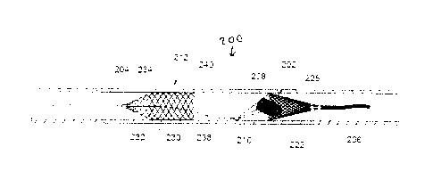
For example, FIGS. 4-6 illustrate another embodiment of a device 200 for
removing emboli and other lumina! blockages. The device 200 also has an
expandable treatment member 202, a soft distal tip 206 (with marked coil), a
delivery
wire 204, control arms 208, a hub 210 and a proximal flow restrictor 212 that
correspond to the expandable treatment member 102, soft distal tip 106 (with
marked
coil), delivery wire 104, control arms 108, hub 110 and proximal flow
restrictor 112,
respectively, for the first embodiment, except for a few differences.
First, the expandable treatment member 202 has a slightly different
configuration. Instead of the conical configuration of the expandable
treatment
member 102, the expandable treatment member 202 has a frusto-conical body 228
where its distal-most end does not terminate in an apex, but has a small
distal
opening.
Second, the proximal flow restrictor 212 has a different configuration, having
a
body that includes a cylindrical distal section 230 and a generally conical
(or frusto-
conical) proximal section 232 that has a tapering configuration. The two
sections 230
and 232 combine to define a receiving section.
CA 03002804 2018-04-20
WO 2017/074721 PCT/US2016/057244
1 3
The body 228 and the sections 230 and 232 can all be laser cut from the same
material (e.g., a NitinolTM tubing or sheet), but the sizes of the cells or
openings 234
in the body 228 and the sections 230 and 232 can be varied to vary the
flexibility of
the different body 228 or sections 230, 232. The section 232 can have an
annular
E: distal edge 240 that functions as an open mouth. The sections 230 and
232 can also
have different size/porosity, and can either be covered by a biocompatible
polymer or
left uncovered. One example is to leave the section 232 uncovered, while
covering
section 230. The uncovered section 232 can be incorporated with other access
catheters to facilitate the aspiration/suction function. The proximal flow
restrictor 112
can have a braided configuration.
Third, the delivery wire 204 can have a deflected section 238 extending
distally from the section 230 at an angle with respect to the central
longitudinal axis to
the hub 210, which is offset from the central longitudinal axis occupied by
the delivery
wire 204. In this regard, the control arms 208 extend from the hub 210 towards
the
body 228 at different angles. The different angles allows the expandable
treatment
member 202 to navigate the vascular anatomy more easily, and also better
facilitates
the collection of clots and particles by the expandable treatment member 202.
In
addition, the different angles for the control arms 208 allow the proximal
opening of
the expandable treatment member 202 to remain open, and not to collapse,
during
the procedure. The different angles also makes it easier for the control arms
208 to
control the diameter or staged deployment of the expandable treatment member
202
during the procedure.
The proximal flow restrictor 212 is configured so that it can experience
relative
movement with respect to the expandable treatment member 202. This is
accomplished by not having a fixed connection between the proximal flow
restrictor
212 and the delivery wire 204, and by allowing the proximal flow restrictor
212 to
slide along the delivery wire 204. In other words, the expandable treatment
member
202 can move independent of the proximal flow restrictor 212. This provides a
more
effective capture and removal of the clot as described below.
31 In use, the device 200 is loaded inside a microcatheter 124, which is
delivered
to a target location in a vessel with the device 200 housed therein using
conventional
delivery techniques that are known to those skilled in the art. The distal end
of the
microcatheter 124 can again be positioned proximal to, or inside, the clot or
embolus
at the target location, and there is no need for the microcatheter 124 to
traverse the
14
clot or embolus. The device 200 can then be pushed distally out of the distal
end of
the microcatheter 124 to expose first the expandable treatment member 202 and
then later on the proximal flow restrictor 212. See FIG. 5. The device 200 is
then
pulled back or withdrawn so that the expandable treatment member 202 catches
the
clot. See FIG. 6A. When the delivery wire 204 is pulled back and the
expandable
treatment member 202 is pulled back with it, the proximal flow restrictor 212
can stay
at the same location within the vessel, so that when the annular distal edge
240 of
the proximal flow restrictor 212 contacts the annular proximal edge or ring
222 of the
body 228, and further proximal pulling of the delivery wire 204 will cause the
expandable treatment member 202 to be pulled back into the cylindrical section
230
so that the entire device 200 is removed from the vessel. As a result, the
entire clot
or embolus can be retained inside a cage defined by the expandable treatment
member 202 and the proximal flow restrictor 212 during removal so as to
prevent
dislodgement or disengagement of the clot. See FIG. 6B. The expanded diameter
of
the annular proximal edge 222 is preferably slightly smaller than the expanded
diameter of the cylindrical section 230 and its annular proximal edge 240 so
that the
expandable treatment member 202 can be retained inside the cylindrical section
230.
In addition, it is possible to provide the delivery wire 204 with a lumen that
opens at an opening that is located inside the proximal flow restrictor 212
(see FIGS.
13-14 below), so that suction can be applied from the proximal end of the
access
guide catheters or microcatheter 124 to pull smaller clots and particles into
the
proximal flow restrictor 212 using suction force, and then removed from the
vessel.
Finally, the suction/aspiration action through the lumen of the access devices
and the encapsulation of the expandable treatment member 102 (with clot
engaged)
23 can happen either simultaneously or in sequence during the procedure.
FIGS. 7-9 illustrate another embodiment of a device 300 for removing emboli
and other lumina! blockages. The device 300 is similar to the device 200 in
that it
also has an expandable treatment member 302, a delivery wire 304, a hub 310
and a
proximal flow restrictor 312 that correspond to the expandable treatment
member
202, delivery wire 204, hub 210 and proximal flow restrictor 212,
respectively, for the
second embodiment, except for a few differences.
First, the expandable treatment member 302 has a different configuration, and
can be configured as any of the removal devices disclosed in co-pending United
States Publication No. 2015-0150672, filed January 16, 2015.
Date Recue/Date Received 2023-04-13
15
For this
reason, there ae no control wires 108/208.
Second, the proximal flow restrictor 312 can be essentially the same as the
proximal flow restrictor 212 in FIGS. 4-6.
Third, the hub 310 can function as a marker or stopper. During the procedure,
when the expandable treatment member 302 is being pulled back, the expandable
treatment member 302 will start to pull the proximal flow restrictor 312 with
it once the
hub 310 reaches and engages the proximal end of the inside of the proximal
flow
restrictor 312. At this stage, the entire (or portion of) expandable treatment
member
.. 302 with its collected clot would already be retained inside the proximal
flow restrictor
312. Again, suction force can be applied from the proximal end of the access
guide
catheter or microcatheter to help pull all the clots/emboli inside the
proximal flow
restrictor 312.
Again, the body of the expandable treatment member 302 and the sections of
the proximal flow restrictor 312 can all be laser cut from the same material
(e.g., a
Nitinol TM tubing or sheet), but the sizes of the cells or openings in the
expandable
treatment member 302 and the proximal flow restrictor 312 can be varied to
achieve
varying flexibilities. The proximal tapered portion on the proximal flow
restrictor 312
can be uncovered, while the straight portion of the proximal flow restrictor
312 can be
covered, to achieve the desired suction effect and suction control.
As shown in FIG. 7, the clot can be caught on the surface of, and between the
cell spaces, of the expandable treatment member 302, and the expandable
treatment
member 302 pulled inside the proximal flow restrictor 312 (see FIGS. 8-9)
completely
before the entire system (microcatheter and device 300) is removed from the
blood
.7.:5 vessel. Since the proximal flow restrictor 312 has no fixed joint
with the delivery wire
304, it can remain in a fixed location with respect to the delivery wire 304
and the
expandable treatment member 302 so that the expandable treatment member 302
(with the blood clot engaged thereon) can be pulled inside the proximal flow
restrictor
312. The expandable treatment member 302 can be pulled into the proximal flow
restrictor 312 until the hub 310 (acting as a stopper) contacts the narrowed
portion of
the proximal section 332 of the proximal flow restrictor 312. The proximal
portion of
the expandable treatment member 302 has a tapered configuration so that it can
fit
into the narrowed proximal section 332. At this time, the proximal flow
restrictor 312
will move together with the expandable treatment member 302 (and blood clot
Date Recue/Date Received 2023-04-13
CA 03002804 2018-04-20
WO 2017/074721
PCT/US2016/057244
16
housed inside) when the delivery wire 304 is pulled out. The device 300 can be
pulled inside a guide catheter for removal out of the vessel, or can be
removed out of
the vessel without being pulled inside a guide catheter first. Again, suction
force can
be applied from the proximal end of the access guide catheter or microcatheter
to
help pull all the clots/embolus inside the proximal flow restrictor 312.
FIGS. 10-12 illustrate another embodiment of a device 400 for removing
emboli and other luminal blockages. The device 400 is similar to the device
100 in
that it also has an expandable treatment member 402, a delivery wire 404,
distal tip
406 and a proximal flow restrictor 412 that correspond to the expandable
treatment
member 102, delivery wire 104, distal tip 106 and proximal flow restrictor
112,
respectively, for the first embodiment, except for a few differences.
First, the expandable treatment member 402 has a different configuration, and
has a distal section 440 that is essentially the same as the conical body of
the
expandable treatment member 102. However, the expandable treatment member
402 also has a proximal section 442 that is also conically shaped with an apex
444 at
its proximal end and with its largest diameter portion coupled to the largest-
diameter
portion of the distal section 440. The double tapered configuration of the
expandable
treatment member 402 allows its distal end to be softer and less traumatic,
and also
provides a less stiff proximal end, which together allow for easier navigation
of the
vessel anatomy. The distal expandable treatment portion 402 can be either
entirely
or partially covered by polymer materials to block the blood flow (flow from
distal
portion of the vessel to proximal portion of the vessel, so that the
aspiration effect
from the access catheter and proximal flow restrictor will be more effective).
Second, the proximal flow restrictor 412 can be essentially the same as the
proximal flow restrictor 212 in FIGS. 4-6.
Third, there is no hub 110 and no control wires 108/208.
Again, the body of the expandable treatment member 402 and the sections of
the proximal flow restrictor 412 can all be laser cut from the same material
(e.g., a
NitinolTM tubing or sheet), but the sizes of the cells or openings in the
expandable
treatment member 402 and the proximal flow restrictor 412 can be varied to
achieve
varying flexibilities.
The clot can be engaged on the outside of the distal section 442 (see FIG. 11)
and the expandable treatment member 402 can be pulled inside the proximal flow
restrictor 412 (see FIGS. 11 and 12) completely before the entire system
CA 03002804 2018-04-20
WO 2017/074721
PCT/US2016/057244
17
(microcatheter and device 300) is removed from the blood vessel. Since the
proximal
flow restrictor 412 has no fixed joint with the delivery wire 404, it can
remain in a fixed
location with respect to the delivery wire 404 and the expandable treatment
member
402 so that the expandable treatment member 402 (with the blood clot engaged
on
its outer surface) can be pulled inside the proximal flow restrictor 412. The
aspiration
can be applied during the procedure through the lumen of the access catheter
or
microcatheter and the proximal flow restrictor as well.
FIGS 13A, 13B, and 13C show some exemplary design configurations for the
braided proximal flow restrictor. The proximal flow restrictor shown in FIGS.
13A-13C
and 14A-14B can be the same the proximal flow restrictor 212, although the
principles and concepts embodied in FIGS. 13A-130 and 14A-14B also apply to
the
other proximal flow restrictors shown and described herein.
As shown in FIG. 13B, the proximal flow restrictor 212 can have a central
lumen 260 at the proximal end 262, a tapering proximal portion 232, and a
cylindrical
distal portion 230. The proximal portion 232 can be uncovered, and the distal
portion
230 can be covered by biocompatible polymer materials. In use, suction can be
applied through the central lumen 260 from the access catheters.
As shown in FIG. 13B, a push wire 264 can be connected to the proximal
portion 232 to operate the proximal flow restrictor 212. This design can be
used or
.. incorporated with other commercially-available clot removal devices, and
can also be
used or incorporated with an access catheter, guide catheter, DAC, or
microcatheter
to apply suction during the clot removal procedure.
As shown in FIG. 13C, a different central lumen structure 260a having a lumen
can be connected to the proximal portion 232 to operate the proximal flow
restrictor
212. This design can be used or incorporated with other commercially-available
clot
removal devices, and can also be used or incorporated with an access catheter,
guide catheter, DAC, or microcatheter to apply suction during the clot removal
procedure.
FIGS. 14A and 14B show an exemplary application of the proximal flow
restriction feature. The proximal portion 232 can be fully uncovered or
partially
uncovered, and the distal portion 230 can be covered by biocompatible polymer
materials. In use, the proximal flow restrictor 212 can be delivered to the
target
location through a microcatheter or other access catheter 224. The proximal
central
lumen 260 can be used to slide along a guidewire or the push wire 264 of the
clot
CA 03002804 2018-04-20
WO 2017/074721 PCT/US2016/057244
18
retrieval device. Adjusting the relative position/location of the
microcatheter 224 with
that of the proximal flow restrictor 212, the proximal flow restrictor 212 can
either
allow proximal forward flow, or cut off the forward flow. In the situation
where forward
flow is cut off, the suction effect can be applied through the lumen of the
microcatheter 224 for improved clot collection, retention and removal. For
example,
when the push wire 264 connected to the proximal flow restrictor 212 is pulled
back
towards the access catheter or microcatheter 224, and the uncovered proximal
portion 232 is completely covered by the distal end of the access catheter or
microcatheter 224 with the covered distal portion 230 forming a seal with the
distal
SC end of the access catheter or microcatheter 224, the forward flow is
totally cut off,
and then the aspiration/suction can be applied from the proximal end of the
access
catheter or microcatheter 224 to help retain and collect clots (as shown in
FIG. 14B).
From FIG. 14B, it is noted that the outer diameter of the access catheter 224
is less
than the outer diameter of the fully expanded distal portion 230, but that
this seal can
still be formed when the proximal end of the distal portion 230 is pulled into
the distal
opening of the access catheter 224 as the proximal part of the distal portion
230
begins to compress and assume a tapered configuration as the distal portion
230 is
pulled into the access catheter 224.
FIGS. 15A-15C illustrate a different embodiment of the present invention,
where the device 200 comprises only the flow restrictor 212 and the push wire
264,
and where the expandable treatment member 202 is omitted. As shown in FIG.
15A,
the distal portion 230 is positioned proximal to the blood clot or embolus,
and the
relative position/location of the access catheter 224 is adjusted by operating
the push
wire 264, so that the proximal portion 232 of the flow restrictor is covered
by the distal
end of the access catheter 224. Aspiration is then applied to the lumen of the
access
catheter 224 to suction or aspirate the blood clot into the distal portion 230
and/or
proximal portion 232 (see FIG. 15B), and then the entire flow restrictor 212
(including
the clot inside) is pulled into the access catheter 224 (see FIG. 15C), and
the device
200 is removed out of the blood vessel.
As an alternative, if the embodiment shown in FIG. 130 is used, the aspiration
can be applied though the central lumen 260a, instead of through the access
catheter 224.
Thus, the embodiment of FIGS. 13C and 15A-150 show that the expandable
treatment member 202 can be omitted and the flow restrictor 212 itself can be
used
CA 03002804 2018-04-20
WO 2017/074721 PCT/US2016/057244
19
to remove blood clots or embolus. The structural arrangement of the flow
restrictor
212 (uncovered proximal portion 232 and covered distal portion 230)
facilitates this
type of removal.
While the description above refers to particular embodiments of the present
E. invention, it will be understood that many modifications may be made
without
departing from the spirit thereof. The accompanying claims are intended to
cover
such modifications as would fall within the true scope and spirit of the
present
invention.