Note: Descriptions are shown in the official language in which they were submitted.
CA 03002891 2018-04-23
WO 2017/072261 PCT/EP2016/075990
1
SENSOR ASSEMBLY
BACKGROUND OF THE INVENTION
The present invention relates to a sensor assembly for in-vivo monitoring of a
body fluid or tissue.
There are many locations within a human or animal body where there are
medical benefits in being able to monitor the pressure in fluid or tissue. For
example, it can be extremely beneficial in understanding the wellbeing of a
patient and understanding the effectiveness of any treatment to the pressure
in a
patient's cranial fluid, within their bladder, muscle compartments, or within
their
circulatory system. Because of these benefits, pressure monitoring systems
have been developed which can be inserted into the body of a patient to
provide
pressure readings.
Conventional pressure monitoring systems typically comprise a pressure sensor
element at the tip of a catheter. A sealant (comprising, for example, a
silicone
gel) is provided over the sensor element to provide a pressure transmission
medium which also seals the sensor element. A problem with this kind of device
is that the fluid being measured tends to leak into the sensor assembly and on
to
the surface of the sensor element because the sealant is prone to distortion
and
as a result does not provide a very effective seal. The leakage can damage and
even disable the sensor element or its electrical connections/circuit.
Furthermore
the sensor assembly may produce unreliable pressure readings, in particular
due to hysteresis effects caused by the distortable sealant. The hysteresis
effects may be exacerbated by leaking fluid. Also, in-use bending of the
small,
flexible tip can disturb the pressure measurement, introducing unwanted
signals
in the pressure detection system.
The present invention aims to alleviate at least to some extent one or more of
the problems of the prior art.
CA 03002891 2018-04-23
WO 2017/072261 PCT/EP2016/075990
2
SUMMARY OF THE INVENTION
The invention is set out in the accompanying claims.
According to an aspect of the invention, there is provided a sensor assembly
for
in-vivo monitoring of a body fluid or tissue, comprising: a pressure sensor
element, comprising a micro-electromechanical system (MEMS) and arranged to
detect a pressure of the body fluid or tissue in use; and a shield, which
generally
surrounds the pressure sensor element such that the pressure sensor element is
within an interior volume of the shield, in order to protect and to prevent
distortion of the pressure sensor element in use; wherein: the pressure sensor
element comprises a biocompatible thin film layer, for resisting corrosion
and/or
fouling of a surface of the pressure sensor element by the body fluid or
tissue or
biological matter thereof; and the pressure sensor element and the shield are
in
fixed relationship with each other.
The invention provides a biocompatible thin film layer which protects a sensor
element from potential corrosion and/or fouling by a body fluid or tissue, or
biological matter thereof. The sensor element is further protected by a
surrounding shield, which is in fixed relationship with the sensor element.
The
shield is a "stiffener" which has a stiffness that is sufficient to reduce or
eliminate
stress on the sensor element (and preferably its electrical connections),
which
may result for example from bending or twisting of the sensor tip. Hence
inadvertent mechanical stress in the sensor element, which could lead to
undesirable flexure of the pressure-sensitive part of the sensor element and
thereby measurement error, can be prevented. Spurious pressure
measurements and sensor damage can therefore be avoided.
Thus the biocompatible thin film layer and the shield function together in a
synergistic manner to protect the sensor element from corrosion/biofouling and
mechanical stress. Advantageously the problematic sealant, required by
conventional sensor assemblies as discussed herein above, may be dispensed
CA 03002891 2018-04-23
WO 2017/072261 PCT/EP2016/075990
3
with. Thus the inventive sensor assembly provides improved accuracy of
measurement along with better system reliability and efficiency.
The sensor assembly may comprise a support which supports the pressure
sensor element within the interior volume of the shield, the shield having a
stiffness
which is greater than the stiffness of the support. The support may comprise a
portion of a printed circuit board (PCB). Preferably the shield has a
stiffness or
rigidity, which is sufficient to reduce or eliminate unwanted stress on the
pressure sensor element and electrical interconnects between the pressure
sensor element and an associated circuit (e.g. of a printed circuit board).
The
shielding structure may be of greater stiffness than the pressure sensor
element.
The pressure sensor element may be fixed relative to the shield by a filler
material which fills a cavity in the interior volume of the shield. The shield
may
comprise a tube. The tube may have an oval cross-section. The pressure sensor
element may be positioned adjacent to a first end opening of the tube. Where
present, the filler material may be arranged to seal a second end opening of
the
tube so as to prevent the passage of the body fluid or tissue through the
second
end opening. The filler material may comprise a cured adhesive. The adhesive
may be biocompatible.
The tube may comprise a cut-out which forms an aperture which intersects the
first end opening, the pressure sensor element being positioned below the
aperture. The cut-out may be inclined relative to the longitudinal axis of the
tube.
Or, the cut-out may comprise a flat portion and a curved portion such as to be
S-
shaped in profile. The aperture, which is provided by the cut-out, allows for
improved flow and/or circulation of the fluid and improved contact to the
tissue
being measured. This can help to prevent clogging of the pressure sensor
element by tissue or body fluid or biological material thereof, and may
prevent
the undesirable formation of gas bubbles over the sensor element which could
interfere with its function. The shield and aperture can prevent artefacts
from the
pressure sensor element coming into contact with more dense structures in the
body, for example cartilage, bone or fibrous tissue.
CA 03002891 2018-04-23
WO 2017/072261 PCT/EP2016/075990
4
The biocompatible thin film layer may have a submicron thickness. The
thickness of the layer may be between 20 and 200 nm. The thickness of the
layer may be about 30 nm. The layer may comprise a coating. The layer may
comprise Al-Ti-oxide. The layer may comprise A1203 + Ti02. Other biocompatible
materials may be used for the thin film layer which also can prevent (or at
least
reduce) corrosion and/or biofouling of the pressure sensor element. Examples
of
other suitable materials for the thin film layer include, but are not limited
to,
Diamond-Like-Carbon (DLC), Hydroxyapatite (HA), Silicon Carbide (SiC), and
Parylene. The thin film layer may comprise a sandwich structure including a
combination of any of the suitable materials.
According to another aspect of the invention, there is provided a sensor
system,
comprising: a sensor assembly as described herein above; and a catheter hose,
configured to connect to the shield of the sensor assembly. Each of the shield
and the catheter hose may comprise an oval cross-section, an end of the shield
being insertable in an end of the catheter hose, the system comprising a tube
or
cannula having an oval cross-section for receiving the catheter hose, the
pressure sensor element being prevented from rotating about a longitudinal
axis
of the tube or cannula when the end of the shield is inserted in the end of
the
catheter hose and the catheter hose is inserted in the tube or cannula.
Advantageously the oval shape prevents the pressure sensor element from
rotating relative to the cannula, thereby improving the positional and/or
directional control of the pressure sensor element during insertion and
retraction.
BRIEF DESCRIPTION OF THE DRAWINGS
Embodiments will now be described, by way of example, with reference to the
accompanying figures in which:
Figure 1 is a perspective cutaway view of a sensor assembly in accordance with
a first embodiment of the invention;
Figure 2 is a longitudinal sectional view of the sensor assembly of Figure 1;
and
Figures 3a and 3b are, respectively, perspective cutaway and longitudinal
sectional views of a sensor assembly in accordance with a second embodiment
of the invention.
CA 03002891 2018-04-23
WO 2017/072261 PCT/EP2016/075990
DETAILED DISCUSSION OF THE EMBODIMENTS
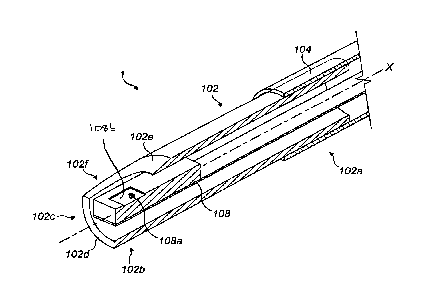
Referring to Figures 1 and 2, a sensor assembly 1 comprises an elongate
5 stiffener tube 102 having a supported end portion 102a and a free end
portion
102b. In this embodiment, the stiffener tube 102 is constructed from AISI 316
stainless steel. The stiffener tube 102 has a length of about 5 mm, an outside
diameter of about 1.2 mm, and a wall thickness of about 0.1 mm. (In other
embodiments the length may be between about 5 and 10 mm).
The supported end portion 102a is inserted in an end of a catheter hose 104
such that the stiffener tube 102 extends outwardly from the catheter hose 104.
An end opening 102c of the stiffener tube 102 is formed by a lip 102d at the
extremity of the free end portion 102b. In this exemplary embodiment, an
oblique
cut-out 102e extends along the free end portion 102b from the lip 102d, in a
plane which is inclined relative to the longitudinal axis X of the stiffener
tube 102,
thereby forming a semi-elliptical aperture 102f which intersects the end
opening
102c.
A generally flat, flexible printed circuit board (PCB) 106 lies in a plane
which is
substantially parallel with the longitudinal axis X of the stiffener tube 102
and
extends from the catheter hose 104 through the interior of the stiffener tube
102,
such that an end 106a of the flexible PCB 106 is disposed at the end opening
102c. More particularly, the end 106a of the flexible PCB 106 is located
within
the enclosure of the free end portion 102b at a short distance d (e.g. about
0.1
mm) from the lip 102d. That is, the end 106a does not protrude from the
stiffener
tube 102.
A pressure sensor element 108 is mounted atop a supporting portion 106b of the
flexible PCB 106 which extends to the end 106a of the flexible PCB 106. The
pressure sensor element 108 comprises a micro-electromechanical system
(MEMS). In this exemplary embodiment the MEMS comprises embedded
piezoresistors, pads and conductors (not visible in Figures 1 and 2), which
are
covered by (i.e. disposed below) a membrane or diaphragm 108a. The
CA 03002891 2018-04-23
WO 2017/072261 PCT/EP2016/075990
6
diaphragm 108a is configured to be deflected by a pressure, which may be
applied to the diaphragm 108a by a body fluid or tissue when the sensor
assembly 1 is in use. The piezoresistors are configured to detect the
deflection
of the diaphragm 108a so that the applied pressure can be measured.
A biocompatible thin film layer 108b extends over the diaphragm 108a so as to
cover the diaphragm 108a. In this exemplary embodiment the thin film layer
108b comprises A1203 + Ti02. In this embodiment the thin film layer 108b has a
thickness of about 30 nm. Alternatively, whatever the material composition of
the
thin film layer 108b, the thickness may typically be anywhere in the range 20
to
200 nm, or even thicker. Typically the thickness will be a submicron
thickness. In
use the thin film layer 108b resists (and preferably prevents) corrosion
and/or
fouling of the surface of the pressure sensor element 108 by a body fluid or
tissue or biological matter thereof. Thus the thin film layer 108b
protectively
covers the pressure-sensing diaphragm 108a, piezoresistors, pads and
conductors, in order to avoid damage to the surface of the pressure sensor
element 108.
Alternatively the pads and conductors may be disposed on top of (i.e. above)
the
diaphragm 108a, with the piezoresistors covered by (i.e. disposed below) the
diaphragm 108a. In that case the biocompatible thin film layer 108b directly
covers the pads and conductors as well as the diaphragm 108a.
The pressure sensor element 108 is electrically connected to the flexible PCB
106 by a plurality of wires 106c, each of which comprises gold in this
embodiment. Alternatively the wires may comprise other metals, for example
aluminium, as will be apparent to the skilled reader. The ends of the wires
106c
are bonded to the pressure sensor element 108 and the flexible PCB 106, at a
transition region of the pressure sensor element 108 and the flexible PCB 106.
The stiffness of the stiffener tube 102 is greater than the stiffness of the
transition region. The ends of the wires 106c are additionally protected by a
glob
top 106d as will be explained later herein.
CA 03002891 2018-04-23
WO 2017/072261 PCT/EP2016/075990
7
An end of the pressure sensor element 108 is aligned with the end 106a of the
flexible PCB 106. Accordingly, a portion of the pressure sensor element 108 is
disposed adjacent to the end opening 102c and in particular a portion of the
pressure sensor element 108 is positioned below the semi-elliptical aperture
102f of the free end portion 102b. No part of the pressure sensor element 108
protrudes beyond the lip 102d or out of the semi-elliptical aperture 102f.
That is,
the pressure sensor element 108 is contained entirely within the interior
volume
of the stiffener tube 102. Accordingly, the stiffener tube 102 provides a
protective
sheath or shield around the pressure sensor element 108. In other words, the
pressure sensor element 108 is protectively covered by the stiffener tube 102.
In this embodiment, cured epoxy glue 110 fills a major portion of the interior
volume of the stiffener tube 102, and a portion of each of the flexible PCB
106
and pressure sensor element 108 is embedded in the epoxy glue 110, such that
the PCB 106 and pressure sensor element 108 are held in substantially fixed
relationship with the stiffener tube 102. The diaphragm 108a of the pressure
sensor element 108 is free from coverage by the epoxy glue 110, so that in use
the diaphragm 108a can be exposed to body fluid or tissue F and deflected by a
pressure thereof, in the manner already described.
The sensor assembly 1 can be used to monitor pressure levels of a fluid or
tissue F in various parts of a patient's body, in order that an assessment of
the
patient's condition can be made. For example, the catheter hose 104 and the
stiffener tube 102 (containing the pressure sensor element 108) may be
inserted, in a conventional manner, through the urinary tract and into the
bladder
of a patient. The inventive sensor assembly 1 is also well-suited to
suprapubic
insertion through the abdominal wall of the patient. It will be understood
that the
sensor assembly 1 may also be inserted into other parts of the body using
appropriate techniques. The protective stiffener tube 102 prevents impacts
between the pressure sensor element 108 and, for example, body tissue or
foreign objects, which might otherwise distort and possibly cause damage to
the
pressure sensor element 108.
CA 03002891 2018-04-23
WO 2017/072261 PCT/EP2016/075990
8
As the sensor assembly 1 is established in position in order to monitor the
pressure, the body fluid or tissue F to be monitored is able to come into
direct
contact with the diaphragm 108a of the pressure sensor element 108 through
the end opening 102c and also the semi-elliptical aperture 102f, so that
accurate
pressure measurements can be made. The sensor assembly 1 is connected to
an electronic module (not shown in the Figures) which is placed externally of
the
patient's body and includes a signal processor. Alternatively, the electronic
module may be located inside the patient's body, at some determined distance
from the pressure sensor element 108 or under the skin, and the signals may be
transmitted wirelessly from the module to an external receiver. Pressure
readings can be taken from the pressure sensor element 108 and processed by
the signal processor over a period of time, for example hours, days, or even
years. As the pressure sensing element 108a monitors the pressure, the solid
epoxy glue 110 within the interior volume of the stiffener tube 102 provides a
seal which prevents fluids from leaking into the catheter hose 104 and the
flexible PCB 106.
At the end of the pressure monitoring period the sensor assembly 1 is
withdrawn
from the patient's body. The stiffener tube 102 protects the pressure sensor
element 108 from impact, distortion and damage.
While the exemplary embodiment described herein above includes a tubular
sheath for protecting the pressure sensor element, it will be understood by
the
skilled reader that the shielding structure may take any one of a variety of
shapes, as long as the structure provides adequate protection in order to
prevent
distortion or damage to the pressure sensor element. Preferably the shielding
structure (e.g. tubular sheath) has sufficient stiffness or rigidity to reduce
or
eliminate unwanted stress on the pressure sensor element, and the electrical
connection between the pressure sensor element and the PCB, thereby to
prevent pressure measurement errors.
It will be further understood that the pressure sensor element may be
configured
and secured in any one of a variety of ways within the protective structure,
and
all of these are within the scope of the claimed invention, provided that at
least a
CA 03002891 2018-04-23
WO 2017/072261 PCT/EP2016/075990
9
part of the pressure sensor element (in the above embodiments, the diaphragm)
is exposed such that the pressure sensor element can come into contact with
the medium to be monitored (e.g. body fluid or tissue, or the like) in order
to
determine the pressure of the medium.
Referring now to Figures 3a and 3b, an alternative embodiment of the invention
differs from the above-described embodiment with respect to the shape of the
cut-out of the stiffener tube 102. In this embodiment, a cut-out 102e' defines
an
aperture 102f' and comprises a flat portion, which extends substantially
parallel
with the longitudinal axis X of the stiffener tube 102, and a curved portion,
such
that the cut-out 102e' is generally "S" shaped in profile (as best illustrated
in
Figure 3b). This form of cut-out is believed to be particularly effective in
preventing the formation of gas bubbles in the aperture 102f over the sensor
element 108, which if present could potentially interfere with the function of
the
sensor element 108.
A sensor assembly 1 according to the invention may be produced according to
the following procedure.
The pressure sensor element 108 is mounted to the supporting portion 106b of
the flexible PCB 106 such that the end of the pressure sensor element 108 is
flush with the end 106a of the flexible PCB 106. The ends of the wires 106c
are
bonded to the flexible PCB 106 and the pressure sensor element 108 to provide
the electrical connection there between. The glob top 106d is provided to
ensure
that the wires 106c are kept in place during the rest of the assembly process,
thereby reducing the possibility of the wires 106c shorting or breaking.
The flexible PCB 106 with the mounted and electrically-connected pressure
sensor element 108 is drawn into the free end portion 102b of the stiffening
tube
102, until the end 106a of the flexible PCB 106 and the end of the pressure
sensor element 108 are at the said distance d from the lip 102d of the free
end
portion 102b and the pressure sensor element 108 is positioned below the semi-
elliptical aperture 102f (or aperture 102f). The epoxy glue 110 is added to
fill the
cavities, between the pressure sensor element 108 (only at the end with
CA 03002891 2018-04-23
WO 2017/072261 PCT/EP2016/075990
electrical connections and glob top 106d) and the flexible PCB 106, and the
interior wall 102g of the stiffener tube 102. The epoxy glue 110 is allowed to
cure
in order to fix and hold the flexible PCB 106 and pressure sensor element 108
in
position relative to the surrounding stiffener tube 102.
5
With the flexible PCB 106 and the pressure sensor element 108 fixably
attached,
the supported end portion 102a of the stiffener tube 102 is drawn into the
catheter hose 104 and held thereto in a snug fit. The dimensions of the
stiffener
tube 102 and catheter hose 104 are selectively matched so as to provide a
10 mechanically stable junction and avoid leakage of fluids between the
stiffener
tube 102 and the catheter hose 104.
It will be understood that the invention has been described in relation to its
preferred embodiments and may be modified in many different ways without
departing from the scope of the invention as defined by the accompanying
claims.
The stiffener tube 102 may be constructed substantially from AISI 316L low
carbon steel. Or, the stiffener tube 102 may be constructed substantially from
plastics, which material may be better suited to long term in-vivo
applications
than metals or metal alloys. Furthermore it will be apparent to the skilled
person
that other materials, including composite materials, may be appropriate for
use
in the stiffener tube 102, and all of these are within the scope of the
claimed
invention.
The wires may be omitted and instead the pressure sensor element 108
electrically connected to the flexible PCB 106 by flip-chip bonding. In this
case,
during assembly gold bumps are made on bond pads of either the flexible PCB
106 or the pressure sensor element 108. The pressure sensor element 108 is
then flipped around and pressed onto the flexible PCB 106 so that the bond
pads bond together with the gold bumps, forming a stack of pad-bump-pad.
CA 03002891 2018-04-23
WO 2017/072261 PCT/EP2016/075990
11
The sensor element 108 may be additionally fixed by use of underfill epoxy
glue.
This ensures a mechanical fixation as well as an electrical connection of the
pressure sensor element 108.
While in the above-described embodiments the pressure sensor element 108
and the stiffener tube 102 are held in fixed relationship with one another
primarily by means of the cured epoxy glue 110, it will be understood that the
fixed relationship may be achieved wholly or partially by different means, all
of
which are within the scope of the claimed invention. For example, some rigid
support may be provided to join or connect the pressure sensor element 108 and
the stiffener tube 102. Alternatively the flexible PCB 106, the supporting
portion
106b of which supports the pressure sensor element 108, may be made
sufficiently rigid to provide an effective fixed relationship between the
pressure
sensor element 108 and the stiffener tube 102. In the absence of solid epoxy
glue 110, an alternative means of sealing may be provided to prevent fluids
from
leaking into the catheter hose 104 and the flexible PCB 106.
It will be understood that the cut-out, of the stiffener tube 102, may take a
variety
of geometrical forms, each of which can provide an aperture over the sensor
element, and all of these are within the scope of the claimed invention.
In an embodiment, the sensor assembly 1 includes a catheter and the PCB 106
is replaced by thin (e.g. golden) wires embedded in the catheter wall.