Note: Descriptions are shown in the official language in which they were submitted.
COMPOSITE PARTS THAT FACILITATE ULTRASONIC IMAGING OF LAYER
BOUNDARIES
Field
The disclosure relates to the field of composite design, and in particular, to
composite
parts.
Background
Composite parts, such as Carbon Fiber Reinforced Polymer (CFRP) parts, are
initially
laid-up in multiple layers that together form an unhardened laminate.
Individual fibers within
each layer of the laminate are aligned parallel with each other, but different
layers may exhibit
different fiber orientations in order to increase the strength of the
resulting composite part along
different dimensions. The laminate may include an unhardened (e.g., viscous
semisolid) resin
that hardens at increased temperature in order to harden the laminate into a
composite part (e.g.,
for use in an aircraft). For thermoset resins, the hardening is a one-way
process referred to as
curing, while for thermoplastic resins, the resin may return to an unhardened
form if it is re-
heated.
In order to ensure that composite parts exhibit an expected level of strength,
it may be
desirable to ensure that fibers within the composite parts do not exhibit
inconsistencies such as
curvature or bends in unexpected locations. However, composite parts are
opaque and hence
destructive testing is needed to check for internal inconsistencies because
the current state of
Non-Destructive Imaging (NDI) yields results that do not have a desired level
of clarity. For
example, destructive testing may involve removing a sample from a composite
part, and visually
inspecting intersections between layers of the sample for inconsistencies. In
this manner, a
technician may carefully cut the composite part to reveal internal sections
thereof. . This
technique alters the structure of the composite part which is tested, and also
quantifies only the
portion of the composite part that is proximate to the sample.
Designers of composite parts continue to seek out enhanced techniques for
imaging the
internal composition of composite parts. Therefore, it would be desirable to
have a method and
apparatus that take into account at least some of the issues discussed above,
as well as other
possible issues.
CA 3003021 2018-04-27
Summary
Embodiments described herein provide for enhanced composite parts that exhibit
a
substantially altered elastic modulus at a boundary between internal layers of
fiber-reinforced
material. For example, these composite parts may utilize internal pores or
particles at the
boundary to cause this change in elastic modulus. By causing a change in
elastic modulus at the
boundary, acoustic impedance of the composite part is altered at the boundary.
This allows for
high-contrast imaging of the boundary via ultrasound.
One embodiment is a method that includes providing an object having multiple
layers of
fibers and resin, inducing ultrasonic waves at locations along the object, and
attenuating the
ultrasonic waves at the regions due to regions interspersed among the layers
that each exhibit an
elastic modulus distinct from an elastic modulus of the fibers and distinct
from an elastic
modulus of the matrix. The method further includes receiving the attenuated
ultrasonic waves,
and analyzing the attenuated ultrasonic waves to determine depths of the
regions.
A further embodiment is a method that includes laying up a layer of fiber-
reinforced
material comprising fibers and a matrix of unhardened resin, and interspersing
material that is
distinct from the fibers and the matrix onto a surface of the layer.
A further embodiment is a product that includes a composite part. The
composite part
includes layers of fiber-reinforced material, each of the layers contacting
another of the layers.
Each of the layers includes fibers and a matrix of hardened resin. The
composite part also
includes regions that are interspersed among the layers, and that have an
elastic modulus that is
distinct from an elastic modulus of the fibers and that is distinct from an
elastic modulus of the
matrix.
A further embodiment is a product that includes a laminate for hardening into
a
composite part. The laminate includes layers of fiber-reinforced material,
each of the layers
contacting another of the layers, each of the layers comprising fibers and a
matrix of unhardened
resin surrounding the fibers. The laminate also includes regions that are
interspersed among the
layers. Each region exhibits an elastic modulus distinct from an elastic
modulus of the fibers and
distinct from an elastic modulus of the matrix.
A further embodiment is an apparatus. The apparatus includes a Composite Tape
Layup
Machine (CTLM). The CTLM includes a head that lays up a fiber-reinforced layer
of a laminate
that comprises fibers and a matrix of unhardened resin, a dispenser that
dispenses a material that
CA 3003021 2018-04-27
2
is chemically distinct from the fibers and the matrix, and a controller that
directs the dispenser to
intersperse the material onto a layer being laid-up by the head.
Yet another embodiment is a method of inspecting a composite structure. The
method
includes laying up a composite structure of fibers and a matrix of resin. The
method also includes
interspersing, at a predetermined strategic location within the composite
structure, a material that
is distinct from the fibers and the resin. Furthermore, the method includes
interrogating the
composite structure via ultrasound, and imaging the predetermined strategic
location of the
material within the composite structure via the ultrasound inspection.
Yet another embodiment is a method for ultrasonic imaging of composite parts,
the
method comprising: providing an object comprising multiple layers of fibers
and a matrix of resin;
inducing ultrasonic waves at locations along the object; attenuating the
ultrasonic waves due to
regions interspersed among the layers that each exhibit an elastic modulus
distinct from an elastic
modulus of the fibers and distinct from an elastic modulus of the matrix;
receiving the attenuated
ultrasonic waves; and analyzing the attenuated ultrasonic waves to determine
depths of the
regions.
Yet another embodiment is an apparatus comprising: a Composite Tape Layup
Machine
comprising: a head that lays up a fiber-reinforced layer of a laminate that
comprises fibers and a
matrix of unhardened resin; a dispenser that dispenses a material that is
chemically distinct from
the fibers and the matrix; and a controller that directs the dispenser to
intersperse the material onto
a layer being laid-up by the head.
Yet another embodiment is a method comprising: laying up a layer of fiber-
reinforced
material comprising fibers and a matrix of unhardened resin; spraying material
that is distinct
from the fibers and the matrix onto a surface of the layer; compacting the
layer and the material;
and laying up an additional layer of fiber-reinforced material onto the
material after compacting
the layer and the material.
Yet another embodiment is a method of inspecting a composite structure
comprising:
laying up a composite structure of fibers and a matrix of resin;
interspersing, at a predetermined
strategic location within the composite structure, a material that is distinct
from the fibers and the
resin; interrogating the composite structure via ultrasound; and imaging the
predetermined
strategic location of the material within the composite structure via the
ultrasound inspection.
3
Date Recue/Date Received 2021-09-20
Yet another embodiment is a product comprising: a laminate for hardening into
a composite
part, the laminate comprising: layers of fiber-reinforced material, each of
the layers contacting
another of the layers, and each of the layers comprising fibers and a matrix
of unhardened resin
surrounding the fibers; and regions that are interspersed among the layers,
each region exhibiting
an elastic modulus distinct from an elastic modulus of the fibers and distinct
from an elastic
modulus of the matrix.
Yet another embodiment is a method of inspecting a composite structure
comprising:
laying up a composite structure of fibers and a matrix of resin;
interspersing, at a predetermined
strategic location within the composite structure, a material that is distinct
from the fibers and the
resin; interrogating the composite structure via ultrasound; and imaging the
predetermined strategic
location of the material within the composite structure via the ultrasound
inspection.
Other exemplary embodiments (e.g., methods and computer-readable media
relating to the
foregoing embodiments) may be described below. The features, functions, and
advantages that
have been discussed can be achieved independently in various embodiments or
may be combined in
yet other embodiments further details of which can be seen with reference to
the following
description and drawings.
Description of the Drawings
Some embodiments of the present disclosure are now described, by way of
example only,
and with reference to the accompanying drawings. The same reference number
represents the same
element or the same type of element on all drawings.
FIGS. 1-4 are diagrams illustrating a composite part that has been enhanced
with high-
strength particles at an intersection between layers of the composite part.
FIGS. 5-6 are diagrams illustrating ultrasonic imaging of the enhanced
composite part of
FIG. 1A in an exemplary embodiment.
FIG. 7 is a flowchart illustrating a method of imaging an enhanced composite
part via an
ultrasonic imaging system in an exemplary embodiment.
FIG. 8 is a diagram illustrating a Composite Tape Layup Machine (CTLM) that
dispenses
material between layers of a laminate in an exemplary embodiment.
FIG. 9 is a flowchart illustrating a method of fabricating an enhanced
composite part in an
exemplary embodiment.
FIG. 10 is a block diagram of a fabrication environment for enhanced composite
parts in an
exemplary embodiment.
FIG. 11 is a flow diagram of aircraft production and service methodology in an
exemplary
embodiment.
3a
Date Recue/Date Received 2021-09-20
FIG. 12 is a block diagram of an aircraft in an exemplary embodiment.
Description
The figures and the following description illustrate specific exemplary
embodiments of
the disclosure. It will thus be appreciated that those skilled in the art will
be able to devise
various arrangements that, although not explicitly described or shown herein,
embody the
principles of the disclosure and are included within the scope of the
disclosure. Furthermore,
any examples described herein are intended to aid in understanding the
principles of the
disclosure, and are to be construed as being without limitation to such
specifically recited
examples and conditions. As a result, the disclosure is not limited to the
specific embodiments
or examples described below, but by the claims and their equivalents.
The following FIGS. describe enhanced composite parts, as well as techniques
and
systems that utilize ultrasonic scanning/imaging in order to analyze the
internal boundaries
between layers of those parts.
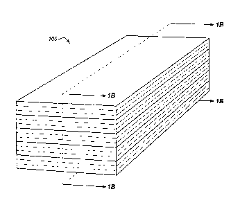
FIGS. 1-4 are diagrams illustrating composite part 100 in an exemplary
embodiment.
Specifically, FIG. lA illustrates a perspective view of composite part 100 in
an exemplary
embodiment, and FIG. 1B illustrates a side view of composite part 100 in an
exemplary
embodiment indicated by view arrows 1B of FIG. 1A. In this embodiment,
composite part 100
includes layers 110, 112, 114, 116, and 118. Each layer includes a matrix 162
of hardened (e.g.,
cured, solid) resin, as well as fibers 164. In this embodiment, a boundary 150
between layers
114 and 116 has been altered by the inclusion of regions 170. Regions 170
exhibit a changed
elastic modulus with respect to the elastic modulus of matrix 162 and fibers
164. This
characteristic alters the acoustic impedance of composite part 100 at boundary
150, which
enhances the quality of ultrasonic images taken of boundary 150. Specifically,
the change in
acoustic impedance causes incoming ultrasonic waves from surface 120 to
reflect sharply and
strongly off of boundary 150, which enables the depth of boundary 150 to be
accurately and
reliably measured.
FIG. 2 is a partially exploded side view of composite part 100 in an exemplary
embodiment. In this view, layers 114 and 116 have been separated in order to
illustrate
boundary 150 between these layers. In this case, boundary 150 is defined by
surface 240 of layer
116 and surface 230 of layer 114, which are in contact despite their apparent
separation in this
exploded view. Boundary 150 may represent an intersection between layers of
composite part
CA 3003021 2018-04-27
4
100 that is likely to exhibit an inconsistency, should an inconsistency exist
in composite part
100. For example, boundary 150 may comprise an intersection between layers
that has
previously been determined to exhibit the greatest amount of inconsistency
whenever an
inconsistency exists within composite parts of the same design. In particular,
boundary 150 may
comprise an intersection between layers that may exhibit inconsistencies that
are out of
tolerance. Such a determination may be made by historical testing of similar
composite parts, by
Finite Element Modeling (FEM) of composite part 100 predicting locations where
inconsistencies may be found, etc. Thus, these determinations and/or
predictions may be
facilitated by past experience in manufacturing composite structures in
general as well as past
experience pertaining to this particular design for a part..
As mentioned above, regions 170 have a substantially altered elastic modulus
when
compared with layers of composite part 100. For example, regions 170 may have
comprise
particles that have a much higher elastic modulus than matrix 162 and fiber
164 with respect to
transverse force (F) applied to composite part 100, such as four to seventy-
five times as high. In
.. a further example, regions 170 may comprise a material that has a much
lower elastic modulus
than matrix 162 (e.g., on the order of Kilopascals (KPa) per square meter
instead of Gigapascals
(GPa) per square meter), or may even comprise small voids/pores at boundary
150 that have no
definable elastic modulus. As used herein, a void/pore having no definable
elastic modulus is
considered to have an elastic modulus of zero. In any case, regions 170 alter
the acoustic
impedance of composite part 100 at boundary 150, which results in enhanced
detection of the
depth of boundary 150 within composite part 100. In embodiments where regions
170 comprise
voids/pores, it may be desirable to carefully control void size and
distribution. .
Regions 170 occupy a small portion of boundary 150 (e.g., surface 230) per
unit area.
This ensures that overall bond strength between layer 114 and layer 116 is not
substantially
reduced and that interlaminar bond strength remains high (e.g., matrix 164 of
resin is not
substantially interfered with by the presence of regions 170). For example,
regions 170 may
occupy between one and ten percent per unit area of boundary 150. Individual
regions 170 may
be particularly small. For example, regions 170 may have a size that is based
on the wavelength
of ultrasound utilized to image composite part 100. Thus, it may be desirable
for regions 170 to
be as wide across as at least one quarter of the wavelength of ultrasound that
will travel through
composite part 100 during imaging. In an embodiment where fiber diameters
range between five
and seven micrometers, and fibers 164 are encased in a thermoplastic veil of
between twenty and
sixty micrometers, an individual region 170 may be less than forty micrometers
across and
CA 3003021 2018-04-27
5
placed directly into the thermoplastic veil. In further embodiments, regions
170 are utilized in
place of a thermoplastic veil. In short, regions 170 are sized to facilitate
non-destructive imaging
of regions of interest within composite part 100 via ultrasound.
FIG. 3 is a view of surface 230 of layer 114 in an exemplary embodiment.
Specifically,
FIG. 3 corresponds with view arrows 3 of FIG. 2. In this embodiment, regions
170 are evenly
and uniformly distributed/interspersed across surface 230, and are illustrated
as small dots.
While individual regions 170 may be located randomly, the density of regions
170 per unit area
(e.g., per meter, per centimeter, per millimeter) remains uniform and/or
constant.
FIG. 4 is a zoomed-in view of area 4 of FIG. 1B. Both FIG. 4 and FIGS. 1-2 are
therefore side views. FIG. 4 illustrates inconsistencies 410, 420, and 430
which may be hidden
within area 4 where they cannot be visually inspected. Due to the inclusion of
regions 170,
inconsistencies 410, 420, and 430, which are located along boundary 150
between layer 116 and
layer 114, will exhibit desirable imaging characteristics when analyzed via
ultrasound. FIG. 4
further illustrates that fibers 164 within layer 114 and layer 116 may
gradually diminish in
magnitude of inconsistency as distance increases from boundary 150. In such
circumstances,
there may be no externally discernible details of these internal
inconsistencies. Hence, the
presence of such inconsistencies would be unknown without engaging in testing.
As shown in
FIG. 4, boundary 150 has an expected depth of DO, while inconsistency 410 has
a depth of D1,
inconsistency 420 has a depth of D2, and inconsistency 430 has a depth of D3.
The changes in
depth cause boundary 150 to be inconsistently located depthwise. This is one
reason why they
are referred to herein as "inconsistencies."
Because boundary 150 has been enhanced with regions 170, composite part 100
may be
beneficially tested for inconsistencies via Non-Destructive Imaging (NDI) in
the form of
ultrasound imaging. This eliminates any need for destructive testing, which
helps to preserve the
structural integrity of composite part 100.
While a single (e.g., uncomplex) composite part has been illustrated and
described that
facilitates ultrasonic imaging, these principles also apply to complex
composite parts, such as
stringers, frames, ribs, and other support structure as well as skin panels of
an aircraft. These
principles further apply to environments where two laminates are co-cured
(i.e., cured together
into a single monolithic composite part). These principles also apply to
environments where two
composite parts are co-bonded (e.g., affixed to each other via epoxy). In some
embodiments, it
is particularly desirable to non-destructively scan the interior (e.g., non-
visible) portions of
composite part 100 to identify out of tolerance inconsistencies. Hence,
regions 170 may be
CA 3003021 2018-04-27
6
interspersed at one or more boundaries between layers. At the same time, it
may not be
beneficial to intersperse regions 170 into every boundary between layers, as
composite parts may
include hundreds of layers, and regions 170 may substantially attenuate
ultrasonic waves. Thus,
applying regions 170 at too many boundaries may prevent deep imaging of a
composite part.
With a description of composite part 100 provided above, ultrasonic imaging of
composite part 100 is discussed with regard to FIGS. 5-6. FIGS. 5-6 are
diagrams illustrating an
ultrasonic imaging system 500 in an exemplary embodiment. Ultrasonic imaging
system 500
comprises any combination of devices and/or components capable of acquiring
data points for an
object/part (e.g., composite part 100) by inducing and/or detecting the
oscillation of ultrasonic
waves within that part. In this embodiment, ultrasonic imaging system 500
comprises generator
510 and signal processing unit 520. Generator 510 generates an ultrasonic wave
540 at an
external surface 532 of part 100 as shown in FIG. 5. If generator 510 is
implemented as an
ultrasonic transducer, then wave 540 may be generated by physical vibration at
generator 510.
Alternatively, if generator 510 comprises a laser interferometer (e.g., a
confocal dual cavity laser
interferometer), then generator 510 may fire a laser beam 512 at part 100 to
induce ultrasonic
wave 540.
Ultrasonic wave 540 travels from surface 120 of part 100 through layers of
part 100 and
hits boundary 150. At boundary 150, regions 170 change the physical properties
of part 100 (in
particular, the elastic modulus). This results in a substantial change in
acoustic impedance at
boundary 150. That is, since regions 170 are dispersed (e.g., evenly and
uniformly) across
boundary 150, and since regions 170 have a substantially different elastic
modulus than their
surroundings, they change the acoustic impedance of boundary 150. This results
in wave 540
attenuating and being reflected at boundary 150, which is shown as attenuated
wave 640.
Attenuated wave 640 then is detected by system 500 as shown in FIG. 6. In
embodiments where
generator 510 comprises a transducer, generator 510 may detect the return of
an ultrasonic wave
from boundary 150. In other embodiments, sensor 511 may be used for this
purpose. In this
embodiment, pulse-echo ultrasonic imaging is described. However, in further
embodiments
through-transmission ultrasonic imaging may be utilized. When engaging in
through-
transmission ultrasonic imaging, a pass-through attenuated wave may be
detected instead of
reflected attenuated wave 640. In further embodiments, regions 170 may be
dispersed within
one or more specific portions (e.g., areas) of boundary 150 that will be
imaged via ultrasound,
instead of being dispersed along the entirety of boundary 150. This enhances
imaging of these
specific portions.
CA 3003021 2018-04-27
7
Signal processing unit 520 analyzes data acquired by imaging system 500 in
order to
determine the depth (D) of boundary 150, which may change with the presence of
inconsistencies at boundary 150. For example, signal processing unit 520 may
detect a large
change in amplitude (i.e., a large value for the derivative of amplitude) at a
given point in time,
and may calculate a depth of boundary 150 at a location based on this point in
time. In this
embodiment, signal processing unit 520 includes interface (I/F) 526 which
retrieves signal data
for attenuated wave 640 (e.g., a reflected version of an ultrasonic wave 540
induced via
generator 510). Signal processing unit 520 further includes sensor 511 which
detects induced
ultrasonic waves, memory 524, which stores data acquired via I/F 526, and
controller 522 which
analyzes data maintained in memory 524. In further embodiments, signal
processing unit 520
may be independently implemented from system 500 (e.g., as an independent
computer).
Surface 532 and material 534 are also depicted.
I/F 526 may comprise any suitable data interface, such as a wired data
connection, or a
wireless transceiver. Memory 524 may comprise any component configured to
store data for
.. retrieval, including for example Random Access Memory (RAM), flash memory,
a hard disk,
etc. Controller 522 may be implemented, for example, as custom circuitry, as a
processor
executing programmed instructions, or some combination thereof
Further details of the operation of imaging system 500 will be described with
regard to
method 700 of FIG. 7. Assume, for this embodiment, that imaging system 500 is
being operated
by signal processing unit 520, and that part 100 has been placed proximate to
imaging system
500 for analysis. Imaging system 500 will utilize ultrasonic techniques to
image/scan part 100 at
multiple locations (e.g., along X and/or Z), and will further review this data
to determine whether
the depth of boundary 150 remains consistent, or if inconsistencies exist.
FIG. 7 is a flowchart illustrating a method 700 for ultrasonic imaging in an
exemplary
embodiment. The steps of method 700 are described with reference to imaging
system 500 of
FIG. 5, but those skilled in the art will appreciate that method 700 may be
performed in other
systems as desired. The steps of the flowcharts described herein are not all
inclusive and may
include other steps not shown. The steps described herein may also be
performed in an
alternative order.
An object is provided which includes multiple layers of fibers and resin (step
702). For
example, the object may comprise a laminate. The laminate may include a
material that is
distinct from (e.g., has a different elastic modulus than the fibers and
resin, and/or is chemically
distinct from) the fibers and the resin. As used herein, the term "chemically
distinct" is used to
CA 3003021 2018-04-27
8
describe substances having different chemical structures. The material may be
strategically
placed at a boundary between layers of the laminate, and even may be
strategically placed at
specific portions of the boundary if desired to facilitate ultrasonic imaging
of those portions. The
material may be added to the laminate, or may already be included in the
laminate prior to the
laminate being provided in step 702. Alternatively, the object may comprise a
composite part
100 created by forming (e.g., curing or consolidating) the unhardened resin
into matrix 162 of
solid resin. The hardening process causes the material discussed above to form
regions 170
interspersed among the layers of part 100 that have an elastic modulus that is
distinct from an
elastic modulus of fibers 164, and that is distinct from an elastic modulus of
matrix 162. In one
embodiment, the hardening of the laminate causes the material to change its
elastic modulus,
while in another embodiment, hardening of the laminate does not alter the
elastic modulus of the
material. Thus, the imaging techniques discussed herein may potentially be
performed on
(unhardened) laminates as well as on (hardened) composite parts.
Identification of
inconsistencies between layers (e.g., 114, 116) at the object (e.g., part 100)
is initiated.
The object (e.g., part 100, or a laminate precursor thereof) is located within
scanning
range of imaging system 500. For example, the object may be placed directly
below generator
510 of imaging system 500. Controller 522 directs generator 510 to
induce/apply ultrasonic
waves (e.g., ultrasonic wave 540) at surface 532 of the object (e.g., via
Laser Ultrasound (LUT)
or via an ultrasound transducer) (step 706). The generated wave 540 travels
through material
.. 534 towards boundary 150. Upon reaching boundary 150 between layer 114 and
layer 116,
wave 540 is attenuated (step 708). This is due to regions 170 interspersed
within boundary 150
having an elastic modulus that is distinct from an elastic modulus of fibers
164, and that is also
distinct from an elastic modulus of matrix 162 of resin (see FIG. 4). For
example, regions 170
may have an elastic modulus that is twice as high (or even much higher, such
as seventy-five
times as high) as the elastic modulus of fibers 164 with respect to transverse
force. In a further
example, regions 170 may have an elastic modulus that is much lower (e.g., on
the order of
hundreds K.Pa) than an elastic modulus of fibers 164 (e.g., on the order of
tens of GPa), or may
even comprise voids with no measureable elastic modulus.
Attenuated wave 640 (e.g. a reflected wave) is received for detection by
imaging system
500 (step 710). Controller 522 implements a detection process, such that
incoming signaling is
sampled over a period of time (e.g., one half of a second) during which
attenuated ultrasonic
wave 640 is expected to be received. That is, controller 522 may acquire a
waveform
representing ultrasonic wave 640 during the time period, the waveform
including a plurality of
CA 3003021 2018-04-27
9
data points (each data point having corresponding amplitude data for a point
in time). Controller
522 may then process the plurality of data points to collect a data point that
indicates amplitude
data and time-of-flight data for boundary 150 (e.g., the highest change in
value during the time
period, the highest peak value during the time period, etc.). Thus, according
to exemplary
method 700, the collected/selected data point is utilized to determine a depth
of boundary 150 at
the current location. The data point may be stored in memory 524, and may be
associated with
the location on surface 230 that was scanned. In this manner, controller 522
may analyze
received ultrasonic waves to determine depths of regions 170 (step 712). For
example, controller
522 may determine depths of boundary 150 at various locations along composite
part 100, based
on a timing of received attenuated ultrasonic waves 642. The locations being
analyzed may
correspond with specific portions of boundary 150 at which regions 170 are
placed.
Controller 522 further determines whether or not imaging/sampling/scanning of
the
object has been completed. For some parts, a resolution of many Pixels Per
Inch (PPI) may be
desired to scan the object along one or more axes. Thus, hundreds, thousands,
or even millions
of samples/data points may be acquired in order to form the image/scan. If not
all data points
have yet been acquired, controller 522 selects a new location on the object
for scanning/imaging
and resumes non-destructive imaging of the object. Alternatively, if enough
samples/data points
have been acquired for the scan, then the scan/image has been completed and
may be presented
to a user via a display (e.g., including a touchscreen user interface (not
shown)) or other
presentation device (e.g., speaker). If an inconsistency is detected,
controller 522 may generate a
notification indicating that the inconsistency is present, and/or that an
inconsistency is out of a
predefined tolerance limit in terms of size. The notification may further
indicate a magnitude of
the inconsistency. The user may then address and/or disposition the
inconsistency as desired. .
For example, controller 522 may transmit an instruction to a display (not
shown) that directs the
.. display to present the notification to an operator of imaging system 500.
With a variety of techniques and systems for imaging an enhanced composite
part
included above with regard to FIGS. 5-7, a discussion of systems and
techniques for fabricating
enhanced composite parts is now provided. FIG. 8 is a diagram illustrating a
Composite Tape
Layup Machine (CTLM) 800 that dispenses material 890 onto a surface 813 of a
tape 812 that
will form a boundary between layers of a laminate 816 in an exemplary
embodiment. CTLM
800 may lay up multiple lengths of tape at once in a single "course," and may
further lay up
multiple courses in order to fabricate multiple/additional layers on top of
laminate 816. In this
embodiment, CTLM 800 includes spool 810, from which tape 812 is pulled by
drive roller 820.
CA 3003021 2018-04-27
Drive roller 820 is driven by drive mechanism 822 to draw tape 812 in
direction T across guide
rollers 830 and into head 840. After tape 812 enters head 840, backing 814 is
removed, moved
in direction B, and stored at take-up spool 850. Meanwhile, tape 812 is laid-
up onto laminate
816 via roller 842. Laminate 816 is itself laid-up onto surface 872 of a
forming tool 870 as head
840 proceeds along layup direction L. After tape 812 is laid-up but before
compaction by
compaction roller 844, dispenser 860 is operated to intersperse material 890
from reservoir 861
out through nozzle 862 and onto tape 812. Controller 880 directs the
operations of the various
components of CTLM 800 discussed above. Controller 880 may be implemented, for
example,
as custom circuitry, as a processor executing programmed instructions, or some
combination
thereof
Because CTLM 800 fabricates laminates in an unhardened (e.g., uncured) state,
material
890 dispensed by CTLM 800 may comprise any of a variety of substances. For
example, in
embodiments where laminate 816 will be hardened into a composite part 100
having
embedded/interspersed regions that comprise particles, material 890 may
comprise a powdered
form of such particles. Material 890 may for example comprise nanoscale
particles of forty
micrometers of size and under (e.g., down to three to ten nanometers in size),
and these particles
may comprise aluminum, copper, other metals and/or metallic particles, glass,
sapphire, or even
powdered nanoparticles of diamond. Such particles may be sprayed onto tape 812
in
combination with air, applied onto tape 812 in solution via a liquid that will
dry out prior to
curing, etc. Controller 880 of CTLM 800 may strategically place material 890
such that material
890 is not dispersed at every layer of laminate 816. In further embodiments,
CTLM 800 may
strategically place material 890 along specific portions 819 (e.g., lengthwise
portions) of
laminate 816 as desired.
In some embodiments, material 890 comprises a precursor liquid that will
evaporate
during the curing process of laminate 816, resulting in regions 170 that are
pores. In such
embodiments, dispenser 860 may dispense droplets between one and two
micrometers in size
(e.g., no more than three micrometers in size), which form during curing of
laminate 816 into
pores of sizes between twenty and forty micrometers. Such embodiments may
involve
dispensing the droplets to cover less than one percent of the surface area of
tape 812, as the
pores/voids resulting from such droplets may be an order of magnitude larger
than the droplets
themselves. A suitable precursor liquid may comprise an oil that evaporates
close to the cure
temperature (e.g., between twenty and zero degrees below the cure
temperature). Suitable
CA 3003021 2018-04-27
11
candidates for the precursor liquid comprise alkanes having between nine and
fourteen carbon
atoms, or other olefins.
In yet another embodiment, material 890 comprises a second resin (e.g., a
liquid resin)
having a higher cure temperature than a first resin within tape 812 that will
form matrix 162. In
such an embodiment, first resin within tape 812 may comprise an epoxy amine
resin with a cure
temperature of 350 Fahrenheit (F), while the second resin (i.e., material
890) may comprise a
benzoxazine resin or bismaleimide resin having a higher curing temperature
(e.g., 500-650 F).
Laminate 816 may then be cured into a composite part at the lower temperature
and imaged. At
this temperature, material 890 does not vitrify/solidify. This means that
material 890 remains
viscoelastic while resin within tape 812 has vitrified. Thus, material 890
forms regions that are
filled with uncured resin and therefore cause a change in acoustic impedance
at laminate 816.
Then, after imaging has been completed, the composite part may be re-cured if
desired at the
higher temperature as well, or material 890 may be left uncured at the
composite part.
In further embodiments, tape 812 may be pre-coated with material 890 prior to
storage on
spool 810. In such embodiments, no dispenser is utilized and any suitable CTLM
may lay up
tape 812 to facilitate ultrasonic imaging of boundaries between layers of a
composite part.
In a further embodiment, a method of inspecting a composite structure such as
a laminate
or composite part 100 includes laying up a composite structure of fibers and a
matrix of resin to
form the composite structure, and further includes interspersing, at one or
more predetermined
strategic locations (e.g., portions 819) within the composite structure, a
material that is distinct
from the fibers and the resin. Such materials may, for example, comprise
material 890 of FIG. 8
discussed below. The method may further include interrogating the composite
structure via
ultrasound as discussed above, and imaging the one or more predetermined
strategic locations of
the material within the composite structure via the ultrasound inspection.
FIG. 9 is a flowchart illustrating a method 900 of fabricating an enhanced
composite part
in an exemplary embodiment. The steps of method 900 are described with
reference to CTLM
800 of FIG. 8, but those skilled in the art will appreciate that method 900
may be performed in
other fiber layup environments as desired.
According to FIG. 9, layer 114 of fiber reinforced material comprising fibers
164 and a
matrix 162 of uncured resin is laid-up by head 840 of CTLM 800 (step 902). For
example, layer
114 may comprise a portion of laminate 816, wherein each layer contacts
another layer within
laminate 816. In a further example, layer 114 is a portion of uncured pre-
impregnated ("pre-
preg") CFRP that will be placed onto a roll for later use during layup. CTLM
800 intersperses
CA 3003021 2018-04-27
12
material 890 onto surface 813 of layer 114 (step 904). As shown in FIG. 1B,
layer 114 will
define half of a boundary 150 between layers where an inconsistency may form
when integrated
into a laminate, such as laminate 816. Thus, controller 880 directs dispenser
860 to intersperse
material 890 onto layer 114 (step 904). The application of material 890 may be
performed
strategically based on input from controller 880. Controller 880 may for
example adjust an
amount of air pressure applied to dispenser 860, and or a size of nozzle 862,
in order to achieve a
desired rate of mass flow (and distribution of) material 890 across layer 114.
Material 890 forms
regions 170, which, after curing, will occupy between one and ten percent of a
surface area of
layer 114, and which will exhibit a substantially different modulus of
elasticity than that found in
layer 114 after curing. In this manner, layers (or entire laminates) of
material may facilitate NDI
by providing an enhanced level of visibility when scanned.
In further embodiments, material 890 may be accompanied by other materials
that form
regions 170. These other materials may be chemically distinct from material
890 and/or have a
different modulus of elasticity than material 890. Hence, some regions 170 may
have different
elastic moduli than each other. In this manner, regions 170 may exhibit
multiple different elastic
moduli that are each distinct from an elastic modulus of the fibers and
distinct from an elastic
modulus of the matrix. In one exemplary implementation of this concept,
regions 170 at a first
portion 819 of layer 114 may exhibit a first shared elastic modulus owing to
material 890 (e.g.,
diamond), while regions 170 at a second portion 819 of layer 114 (or even an
entirely different
layer) may exhibit a second shared elastic modulus owing to use of a different
material (e.g.,
sapphire, a different type of resin, or even a void). Both of the shared
elastic moduli are different
from the elastic modulus of the fibers and the elastic modulus of the matrix.
Examples
In the following examples, additional processes, systems, and methods are
described in
the context of fabrication environment for fabricating and/or imaging enhanced
composite parts.
The example will be described with respect to the systems and devices of FIG.
10.
FIG. 10 is a block diagram of a fabrication environment 1000 for enhanced
composite
parts in an exemplary embodiment. Fabrication environment 1000 includes an
imaging system
1002, which includes ultrasonic wave generator 1010, sensor 1011, and signal
processing unit
1020. Signal processing unit 1020 includes backend interface 1026 (e.g., an
internal computer
bus, Universal Serial Bus (USB), etc.) for providing instructions to generator
1010. Signal
processing unit 1020 also includes frontend interface 1028 (e.g., an Ethernet
connection) through
CA 3003021 2018-04-27
13
which reports may be transmitted, and display 1021 (e.g., a screen) for
displaying data to a user.
Control unit 1022 controls the operations of imaging system 1002. FIG. 10
further illustrates
layers 1080, which are being laid-up by CTLM 1050. Each layer 1080 includes
resin 1084, as
well as fibers 1082.
CTLM 1050 includes controller 1052, which manages the operations of CTLM 1050.
Carbon fiber tape 1055 is removed from spool 1054 via drive roller 1056, which
is driven by
drive unit 1058. Tape 1055 continues via guide roller 1060 until reaching head
1062. Head
1062 parts backing 1063 from tape 1055, and stores the backing on take-up
spool 1064. Head
1062 also uses tape 1055 to lay up a layer 1080 along layup direction L. After
layer 1080 is
place by head 1062 but before compaction of layer 1080 by compaction roller
1066, dispenser
1068 applies particles 1074 to layer 1080. In further embodiments, particles
1074 may be
applied at head 1062, or at other upstream or downstream locations as desired.
Specifically,
particles 1074 are removed from reservoir 1070 and ejected via nozzle 1069.
Referring more particularly to the drawings, embodiments of the disclosure may
be
described in the context of an aircraft manufacturing and service method 1100
as shown in FIG.
11 and an aircraft 1102 as shown in FIG. 12. During pre-production, exemplary
method 1100
may include specification and design 1104 of the aircraft 1102 and material
procurement 1106.
During production, component and subassembly manufacturing 1108 and system
integration
1110 of the aircraft 1102 takes place. Thereafter, the aircraft 1102 may go
through certification
and delivery 1112 in order to be placed in service 1114. While in service by a
customer, the
aircraft 1102 is scheduled for routine maintenance and service 1116 (which may
also include
modification, reconfiguration, refurbishment, and so on).
Each of the processes of method 1100 may be performed or carried out by a
system
integrator, a third party, and/or an operator (e.g., a customer). For the
purposes of this
description, a system integrator may include without limitation any number of
aircraft
manufacturers and major-system subcontractors; a third party may include
without limitation any
number of vendors, subcontractors, and suppliers; and an operator may be an
airline, leasing
company, military entity, service organization, and so on.
As shown in FIG. 12, the aircraft 1102 produced by exemplary method 1100 may
include
an airframe 1118 with a plurality of systems 1120 and an interior 1122.
Examples of high-level
systems 1120 include one or more of a propulsion system 1124, an electrical
system 1126, a
hydraulic system 1128, and an environmental system 1130. Any number of other
systems may
CA 3003021 2018-04-27
14
be included. Although an aerospace example is shown, the principles of the
invention may be
applied to other industries, such as the automotive industry.
Apparatus and methods embodied herein may be employed during any one or more
of the
stages of the production and service method 1100. For example, components or
subassemblies
corresponding to production stage 1108 may be fabricated or manufactured in a
manner
similar to components or subassemblies produced while the aircraft 1102 is in
service. Also,
one or more apparatus embodiments, method embodiments, or a combination
thereof may be
utilized during the production stages 1108 and 1110, for example, by
substantially expediting
assembly of or reducing the cost of an aircraft 1102. Similarly, one or more
of apparatus
embodiments, method embodiments, or a combination thereof may be utilized
while the aircraft
1102 is in service, for example and without limitation, to maintenance and
service 1116. For
example, the techniques and systems described herein may be used for steps
1106, 1108, 1110,
1114, and/or 1116, and/or may be used for airframe 1118 and/or interior 1122.
In one embodiment, enhanced composite parts comprise a portion of airframe
1118 (e.g., a
wing), in order to ensure that these parts meet with quality standards before,
after, or during
component and subassembly manufacturing 1108. For example, composite part 100
may be
assembled into an aircraft in system integration 1110, and then be utilized in
service 1114 until
wear renders part 1130 unusable. An imaging system 1002 may be utilized for
example to ensure
that part 100 continues to conform with quality standards. Then, in
maintenance and service
.. 1116, part 100 may be discarded and replaced with a newly manufactured part
100. Thus,
imaging system 1002 may be utilized again in order to ensure that the new part
100 meets quality
standards.
Any of the various control elements shown in the figures or described herein
may be
implemented as hardware, software, firmware, or some combination of these. For
example, an
.. element may be implemented as dedicated hardware. Dedicated hardware
elements may be
referred to as "processors", "controllers", or some similar terminology. When
provided by a
processor, the functions may be provided by a single dedicated processor, by a
single shared
processor, or by a plurality of individual processors, some of which may be
shared. Moreover,
explicit use of the term "processor" or "controller" should not be construed
to refer exclusively
to hardware capable of executing software, and may implicitly include, without
limitation, digital
signal processor (DSP) hardware, a network processor, application specific
integrated circuit
(AS1C) or other circuitry, field programmable gate array (FPGA), read only
memory (ROM) for
CA 3003021 2018-04-27
storing software, random access memory (RAM), non-volatile storage, logic, or
some other
physical hardware component or module.
Also, an element may be implemented as instructions executable by a processor
or a
computer to perform the functions of the element. Some examples of
instructions are software,
program code, and firmware. The instructions are operational when executed by
the processor to
direct the processor to perform the functions of the element. The instructions
may be stored on
storage devices that are readable by the processor. Some examples of the
storage devices are
digital or solid-state memories, magnetic storage media such as a magnetic
disks and magnetic
tapes, hard drives, or optically readable digital data storage media.
Although specific embodiments are described herein, the scope of the
disclosure is not
limited to those specific embodiments. The scope of the disclosure is defined
by the following
claims and any equivalents thereof.
16
Date Recue/Date Received 2021-09-20