Note: Descriptions are shown in the official language in which they were submitted.
CA 03003978 2018-05-02
WO 2017/077365
PCT/IB2015/058555
1
Method and device for obtaining power intended to supply a consuming appliance
from a
conductor traversed by an alternating electrical current
The present invention relates to a method and a device for obtaining a power
intended to
supply a consuming appliance from a conductor traversed by an alternating
electrical
current.
The description below refers, as a preferred embodiment, to a method for
extracting power
used in a power transmission line, and to a device for obtaining power for a
consuming
appliance that is intended to be mounted on a supporting structure for a power
transmission
line, in particular for example on a pylon of a distribution network for
medium-, high- and
very-high-voltage electricity (MV, HV or HHV).
However, the invention should be understood to be viable and applicable to any
system in
which there is at least one conductor traversed by an alternating electrical
current, the
references to power transmission lines not being limiting.
In recent years, the need has arisen to draw electrical power for consuming
appliances
from conductors traversed by a current, in particular in relation to power
transmission
lines.
Indeed, the need to provide electricity distribution networks with electronic
monitoring and
control equipment has increased significantly in recent years, both on account
of safety
requirements and the need to obtain measured electrical parameters within the
network
(smart networks). In general, the aforementioned control equipment includes a
power
supply module able to generate the electrical power (in particular electrical
current)
required to power the control equipment.
A known device for obtaining power to supply a consuming appliance
(hereinafter referred
to more simply using the term "power supply module") is described in Italian
patent IT 1
391 387.
84275705
2
WO 2010/005324 and WO 99/26329 describe inductively coupled power transfer
systems
designed to operate in the vicinity of a magnetic field generated by a
controlled primary
circuit. WO 2010/005324 includes resistive means such as MOS transistors used
in linear
mode to limit the electrical power to the load, which are subject to
disadvantageous power
dissipation and therefore offer low overall system efficiency. WO 99/26329
includes means
for limiting the power for saturation of a magnetic core induced by the flow
of a direct current,
which are also subject to power dissipation and offer low overall efficiency.
The object of the present invention is to propose a method and a device for
obtaining power
intended to supply a consuming appliance from a conductor traversed by an
uncontrollable
electrical current, that makes it possible to increase and improve control of
the power (or
current) generated and supplied to the consuming appliance, while guaranteeing
protection
from extra currents on the conductor without dissipation of the available
power, providing
high efficiency.
Some embodiments disclosed herein provided method for obtaining power intended
to supply
a consuming appliance from a conductor traversed by a primary electrical
current, said method
comprises the following steps: placing, in a position remote from said
conductor, a core of
magnetic material and a conductive solenoid wound about said core to obtain a
secondary
current in the solenoid from a magnetic field flux generated in said solenoid
by said conductor,
core and solenoid, said conductive solenoid being connected to the consuming
appliance by
conversion means adapted to convert said secondary current into a power
intended to supply
the consuming appliance through a related voltage and output current; when the
power
supplied to the consuming appliance increases following an uncontrollable
increase in the
primary current stopping the output current at a threshold value associated
with an imposed
current value that is lower, by a predetermined quantity, than a secondary
saturation current
value of the magnetic material of the core; and when the power applied to the
consuming
appliance increases following a further uncontrollable increase in the primary
current,
detecting the value of the voltage applied to the consuming appliance and when
said value
reaches a predetermined limit value letting an output current greater than
said threshold value
flow, causing saturation of the core and consequently a reduction in the power
applied to the
consuming appliance, wherein a power is produced to supply the consuming
appliance
through a related voltage and output current using the following steps:
transforming the
Date Recue/Date Received 2022-03-07
84275705
2a
secondary current into a comparison voltage using a current transducer;
comparing the
comparison voltage with a reference voltage to produce a comparison current
using an en-or
amplifier connected to the current transducer; producing the output current
supplied to the
consuming appliance using a PWM module in a feedback loop with the error
amplifier
controlling the output current by means of a first division resistance
arranged in series with a
second division resistance, said first and second division resistances being
positioned on the
non-inverting leg of the amplifier, and a first Zener diode arranged in
parallel with the second
division resistance, and causing the output current to exceed a first
threshold value associated
with a secondary saturation current such as to saturate the magnetic material
of the core using
a third division resistance positioned on the non-inverting leg of the
amplifier, a fourth
division resistance and a second Zener diode arranged in series with said
fourth resistance, said
fourth division resistance and second Zener diode being linked between a
connection point
placed on the non-inverting leg of the amplifier between the first division
resistance and the
current transducer and the non-inverting terminal of the amplifier.
Some embodiments disclosed herein provide a device for obtaining a power
intended to
supply a consuming appliance from a conductor traversed by a primary
electrical current, said
device includes: a core of magnetic material and a conductive solenoid wound
about said core
and connected to the consuming appliance, said core and solenoid being
positioned in a
position remote from said conductor; a conversion unit connected to the
solenoid and intended
to be connected to the consuming appliance; said conversion unit being adapted
to transform
at least a portion of the magnetic field flux generated in said solenoid by
said conductor,
magnetic core and solenoid into power intended to supply the consuming
appliance without
there being any electrical contact with said conductor; said conversion unit
including a
converter adapted to receive a secondary current associated with the power
generated from
said magnetic field flux and to transform same into an output current supplied
to the
consuming appliance, and in that said conversion unit is arranged for: when
the power
supplied to the consuming appliance increases following an uncontrollable
increase in the
primary current, stopping the output current at a threshold value associated
with an imposed
current value that is lower, by a predetermined quantity, than a secondary
saturation current
.. value of the magnetic material of the core; and when the power applied to
the consuming
appliance increases following a further uncontrollable increase in the primary
current,
detecting the value of a voltage applied to the consuming appliance and when
said value
Date Recue/Date Received 2022-03-07
84275705
2b
reaches a predetermined limit value letting an output current greater than
said threshold value
flow, causing saturation of the core and consequently a reduction in the power
applied to the
consuming appliance, wherein the conversion unit further includes a rectifier
adapted to
receive the secondary current and to transform same into an intermediate
current, and in that
the converter includes: a current transducer an-anged for receiving the
intermediate current and
converting same into a comparison voltage; an error amplifier connected to the
current
transducer that is adapted to compare said comparison voltage with a reference
voltage and to
produce a comparison current; a PWM module in a feedback loop with the error
amplifier that
is adapted to receive the comparison current and to produce the output
current, wherein the
converter further includes: a first division resistance arranged in series
with a second division
resistance, said first and second division resistances being positioned on a
non-inverting leg of
the amplifier; a first Zener diode arranged in parallel with the second
division resistance, said
first and second division resistances and said first Zener diode being adapted
to control the
output current, wherein the converter further includes: a third division
resistance positioned on
the non-inverting leg of the amplifier; a fourth division resistance and a
second Zener diode
arranged in series with said fourth resistance, said fourth division
resistance and second Zener
diode being linked between a connection point placed on the non-inverting leg
of the amplifier
between the first division resistance and the current transducer and the non-
inverting terminal
of the amplifier; said third and fourth division resistances and said second
Zener diode being
adapted to cause the output current to exceed a first threshold value
associated with a
secondary saturation current such as to saturate the magnetic material of the
core.
Further characteristics and advantages of the present invention are set out in
the detailed
description below, provided purely as a non-limiting example, with particular
reference to the
attached drawings, in which:
- Figure 1 is a front elevation of an example embodiment of a power supply
module
according to the present invention mounted on a pylon of a distribution
network;
Figure 2 is a schematic perspective view of the power supply module in Figure
1;
Figure 3 is an equivalent circuit diagram of the power supply module;
Figure 4a is a graph showing the trend in mutual induction as a function of
the
dimensions of the core;
Figure 4b is a graph showing the trend in self-induction of the core as a
function of the
dimensions of the core;
Date Recue/Date Received 2022-03-07
CA 03003978 2018-05-02
WO 2017/077365 PCT/IB2015/058555
3
- Figure 4c is a graph showing the trend in the ratio between mutual
induction and
self-induction of the core as a function of the dimensions of the core;
- Figure 5 is a graph showing the generated power as a function of the
primary
current;
- Figure 6 is a front and side view of a pylon equipped with a power supply
module
according to the present invention;
Figure 7 is a longitudinal cross-section of a variant of the magnetic core;
- Figure 8 is a transversal cross-section of the plates of the core;
Figure 9 is a complete circuit diagram of the conversion unit of the power
supply
module; and
- Figures 10 to 14 show details of portions of the circuit in Figure 9.
In the description below, all references made to power transmission lines
should be
considered to be qualitatively independent of the form of the pylon, the
number of
conductors (single or double circuit) and the voltage of the electrode.
= The method and the device (or power supply module) according to the
present invention
are described progressively with reference to the structure of a power
transmission line, but
are also applicable to individual conductors traversed by an alternating
electric current.
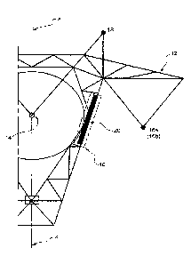
In Figure 1, reference sign 10 indicates an example embodiment of the power
supply
module according to the present invention. The power supply module 10 is
mounted on a
supporting structure (such as a pylon 12) of a single-circuit 380 kV power
transmission
line, which is not illustrated as a whole.
Figure 1 shows only the portion of the pylon 12 located on one side of the
axis of
symmetry X-X of same. The pylon 12 carries a central overhead conductor cable
14 and
first and second lateral overhead conductor cables 16a, 16b, of which only the
first is
shown in the figures. The conductor cables 14, 16a and 16b advantageously form
a three-
phase electricity distribution system. The pylon 12 is also connected to at
least one
overhead protection cable 18.
CA 03003978 2018-05-02
WO 2017/077365 PCT/IB2015/058555
4
Figure 2 is a schematic perspective view of the power supply module in Figure
1. The
power supply module 10 includes a magnetic core 20 of length h and diameter d
including
preferably a set of ferromagnetic bars that is able to convey a portion of the
magnetic field
flux induced by the conductor cables 14, 16a and 16b. For the sake of
simplicity and
clarity, Figure 2 shows only the central conductor cable 14.
The core 20 can be positioned remotely from the conductors 14, 16a and 16b, or
be
separated from same by a predetermined distance, preferably equal to 1 cm per
kV of
voltage in the conductors 14, 16a and 16b (in air).
The power supply module 10 includes a conductive solenoid 22 preferably having
N
copper turns and wound about the magnetic core 20. The conductive solenoid 22
is
connected to a conversion unit 24, described in detail below, that is adapted
to convert the
portion of the magnetic field flux conveyed by the conductors 14, 16a, 16b, by
the
magnetic core 20 and by the solenoid 22 into output electrical energy (or
current) intended
to power a consuming appliance 26, as described in detail below.
Consequently, the magnetic core 20 and the conductive solenoid 22 work as
conversion
means that transform a portion of the magnetic field flux induced by the
overhead
conductors 14, 16a, 16b into output electricity to power the consuming
appliance 26,
without there being any electrical contact with the conductors 14, 16a and 16b
of the power
transmission line.
It should be noted that the distance between the core 20 and said conductors
(up to 5 m),
the linear shape of the core itself (with an open magnetic circuit), and the
impossibility of
controlling the current flowing in the conductors make the present capture
system
absolutely unique in capturing magnetic power from energized cables, operating
at entirely
safe distances.
A description of the physical principles on which operation of the power
supply module 10
according to the present invention is based is given below.
CA 03003978 2018-05-02
WO 2017/077365 PCT/IB2015/058555
For the sake of simplicity and clarity, the considerations set out below make
reference to a
system including the power supply module 10 and the single central conductor
14.
The central conductor cable 14 carrying an alternating current therefore
represents a
5 magnetic field source also referred to as the primary circuit. The
magnetic field generated
by the primary circuit is captured by the magnetic core 20 on which the
solenoid 22 is
arranged. This solenoid 22 is also referred to as the secondary winding or
circuit.
The secondary circuit powers the consuming appliance 26, and the power supply
module
10 must be dimensioned to transfer the maximum real power.
A bar of magnetic material (the magnetic core 20) on which a winding (the
solenoid 22) is
wound and that is immersed in a magnetic field generated by a rectilinear
single-phase
conductor such as the central conductor 14 (for which it is assumed in a known
manner
that the current lines extend to infinity) positioned in a plane perpendicular
to the bar itself,
is affected by two magnetic fluxes, a primary flux 4)ps and a secondary flux
4)ss.
The primary flux ottps, generated by a primary current Ip flowing through the
central
conductor 14, connects with the N turns of the secondary winding 22 resulting
in a primary
winding flux (top equal to:
(I) = N *
PS (1)
The secondary flux 4>ss, generated by the current flowing through the solenoid
22, connects
with the N turns of the secondary winding 22 resulting in a secondary winding
flux 4)s
equal to:
N * Oss (2)
The primary winding flux (1)p. generated by the primary current Ip flowing
from the central
conductor 14 and that is connected with the magnetic core 20, is equal to:
CA 03003978 2018-05-02
WO 2017/077365
PCT/IB2015/058555
6
4>p M * IP (3)
where M is the mutual inductance coefficient between the central conductor 14
and
the secondary winding 22.
This primary winding flux otop generates a no-load voltage Vo on the N turns
of the
secondary winding 22 equal to:
(4)
where co is the angular frequency.
Figure 3 shows a equivalent circuit diagram of the magnetic core 20, of the
conversion unit
24 and of the consuming appliance 26.
This circuit includes an equivalent voltage generator 28 of value o)*M*Ip
representing the
no-load voltage Vo, an inductance 30 of value L linked in a known manner to
the
secondary winding flux 4s, an internal resistance 32 of value R, representing
the total
losses of the core 20 and of the solenoid 22, a capacitance 34 of value C
representing the
conversion unit 24 and a load resistance 36 of value Rc representing the
consuming
appliance 26.
Returning to the description of the physical principles on which operation of
the power
supply module 10 is based, both the losses in the magnetic material of the
core 20 and the
losses caused by the secondary winding 22 shall be temporarily disregarded, in
a way
known per se.
This means that the internal resistance 32 has a value of zero and the N turns
are closed in
a circuit comprising only the load resistance 36 and the capacitance 34, which
is in perfect
resonance with the inductance 30. In this hypothesis, the no-load voltage Vo
generates a
secondary current Is in the solenoid 22 equal to:
CA 03003978 2018-05-02
WO 2017/077365
PCT/IB2015/058555
7
vo _____________________________________
¨Rc 7'7 (5)
Rc
This current generates the secondary winding flux 4:=s that is closely coupled
to the
magnetic core 20.
The presence of the primary winding flux (I)p and the secondary winding flux
(1)s generates
respectively a primary induction Bp and a secondary induction Bs equal to:
Bp = ms* _____________________________ NIP (6)
B5= ¨Ls*INs (7)
where S is the section of the core and L is the inductance of the equivalent
circuit.
The total magnetization Bg of the magnetic core 20 is given by the resultant
vector of the
two inductions:
fl = + (8)
In perfect resonance conditions, the currents Ip and Is are in phase
quadrature with each
other, as are the vectors Bp and Bs.
The graphs in Figures 4a, 4b and 4c are used to analyse the values (modulo) of
Bp and Bs.
These graphs are the result of calculations performed by the inventor
considering, for the
purposes of said calculations, a metal bar positioned at 4 meters from a
conductor, having a
relative magnetic permeability of 105, 500 turns on the secondary winding,
and with
different bar lengths h and diameters d. The graphs in Figures 4a-4c can be
used to obtain
the values of M, L and 0 = M/L .
For example, with a bar of length h equal to 4 m and of diameter equal to 5
cm, the value
of 0 is approximately 0.0002.
CA 03003978 2018-05-02
WO 2017/077365
PCT/IB2015/058555
8
If there is a secondary current Is equal to the primary current Ip, the ratio
Bp/Bs matches
the value of 0, i.e. 0.0002.
This means that it is sufficient to have a secondary current Is equal to 1 A
to obtain an
induction equivalent to that generated by a primary current Ip of 5,000 A.
In operating conditions of a power transmission line, the primary current Ip
usually remains
below 1,500 A, whereby the magnetization of the magnetic core 20 is primarily
due to the
secondary current Is (and therefore to the secondary induction Bs).
The average power Pg generated by the conductor 14, by the core 20 and by the
solenoid
22 on the load resistance Rc is given by the following formula:
p(Ø/p4Bs.Ns.frr ¨ __________________________ (9)
¨
Given that 0 = M/L it can be written:
P * 1 p * Bs*N*S*0 (10)
Supposing A=N*S*0 gives:
Pg = co * 1p * Bs * A (11)
The graph in Figure 4c shows that 0 is proportional to the length of the
magnetic core 20
and independent of S. Furthermore, 0 is known to be inversely proportional to
the number
of turns N.
Other calculations similar to the ones described above (the resulting graphs
of which have
not been shown) carried out by the inventor demonstrated that 0 is also
independent of the
relative magnetic permeability it of the bar, in the case of permeability i-tr
greater than
30,000.
CA 03003978 2018-05-02
WO 2017/077365
PCT/IB2015/058555
9
The expressions set out above show that the factor A is proportional to the
length of the
magnetic core 20 and to S while it is invariant in relation to N and fir.
This shows that the generated power Pg is directly influenced by the volume of
the
magnetic core 20, while being independent of N and of lir (for 1.1,r >
30,000).
Analysing expression (9) reveals that the generated power Pg, all other
conditions such as
network frequency, the material of the core 20, the value of the primary
current Ip etc.,
being the same, is dependent on the volume of the core 20. This means that
cores with
different weights may be made as a function of the power to be supplied.
Preferably, the
core 20 should weigh less than 100 kg.
Increasing the primary current Ip increases the no-load voltage Vo and
consequently also
the secondary current Is (and therefore the secondary induction Bs).
If no limits are imposed (free fluctuation operation), varying the primary
current Ip causes
the generated power Pg to increase according to the square law:
()2
P ¨ (12)
Rc
This free .fluctuation operation of the magnetization ends when the no-load
voltage Vo
induces a secondary current Is that causes a secondary saturation induction
Bss on the
magnetic core 20 equal to the saturation value of the material of the magnetic
core 20. This
occurs for a secondary saturation current Iss equal to:
S*N*Bss
'SS L (13)
This secondary saturation current Iss occurs at a primary saturation current
Ips equal to:
0 = .s*N.Rc.Bss
3 (14)
L*Nl*w
CA 03003978 2018-05-02
WO 2017/077365 PCT/IB2015/058555
When this saturation value has been reached, the material of the magnetic core
20 is
saturated and reducing its magnetic permeability no longer connects the
primary flux ,CDp
cancelling out the induced voltage Vo, the mutual inductance M tends towards
zero and
therefore the generated power Pg is quickly reduced to zero.
5
Figure 5 is a graph showing the generated power Pg as a function of the
primary current ip.
A first curve A shows the trend in the free-fluctuation region. The curve A is
given by the
union of two branches A' and A".
One solution to the problem of zeroing the generated power Pg, according to
the present
invention, involves acting on the load resistance 36 when the secondary
current Is
approaches the secondary saturation current Iss to cause the secondary current
Is to stop at
an imposed current value 1ssi below the secondary saturation current Iss by a
predetermined amount, for example around 1%. This imposed current Iss I should
at this
point remain constant when the primary current Ip increases (imposed
magnetization
operation).
The curve B in Figure 5 represents this condition. The curve B is given by the
union of two
branches A' and B'.
The magnetic core 20 is then in an unsaturated magnetization state and the no-
load voltage
Vo can increase as the primary current 1p increases, causing the generated
power to increase
linearly:
Pg = Vo * Issi = w * M * IP * Issi (15)
The generated power Pg increases linearly until the primary induction Bp
induced by the
primary current Ip, added vectorially to the second induction Bs, brings the
magnetic core
20 to saturation.
To ensure that the magnetic core 20 reaches saturation, the primary current Ip
still needs to
CA 03003978 2018-05-02
WO 2017/077365
PCT/IB2015/058555
11
reach values of several thousands of amperes, thereby causing the no-load
voltage Vo to
reach values able to damage the conversion unit 24.
To prevent this problem occurring, the magnetization of the magnetic core 20
needs to be
controlled again.
The conversion unit 24 (Figure 2), as described in greater detail below, is
equipped with a
voltage sensor that, when it detects that the voltage applied to the consuming
appliance 26
(i.e. the input voltage of the converter described below) reaches a limit
value (preferably
the maximum value of the voltage permitted by the electronic components or by
the heat
dissipation of the system) permits the flow of a secondary current Is greater
than the
imposed current Iss] This causes the magnetic core 20 to become saturated, and
the voltage
applied to the consuming appliance 26, and consequently the generated power Pg
(forced
saturation operation), is reduced.
The curve C in Figure 5 represents this condition. The curve C is given by the
union of the
branches A', B' and C'.
This operation is also useful in instances where it is necessary to limit the
power to be
transferred to the consuming appliance 26 and to protect the conversion unit
24 from
overcurrents (for example, line short-circuits). =
The above description of the physical principles on which operation of the
power supply
module 10 is based considers the power Pg transferred to the magnetic core 20
by the
current flowing through the' central cable 14 only.
Considering instead that the currents flow on all three cables 14, 16a and
16b, the power
transferred to the core 20 varies as a function of the relative position of
the core 20 in
relation to the cables. To increase the power transferred to the core 20
compared with the
case set out above, the core 20 (and therefore the power supply module 10) is
positioned at
a point of the pylon 12 such that one of the cables 14, 16a and 16b is
positioned to the right
of the core 10 and the other two cables are positioned to the left of the core
20.
CA 03003978 2018-05-02
WO 2017/077365 PCT/IB2015/058555
12
In this way, the magnetic flux produced by the cable positioned to the right
of the core 20
is added to the resultant vector of the magnetic flux produced by the cables
positioned to
the left of the core 20.
Figure 6 is considered below by way of example, showing two views of the pylon
12 (in
=this case a 150 kV pylon) on which the power supply module 10 is positioned.
Figure 6a shows the pylon 12 from the front (i.e. the conductor cables 38, 40
and 42 ¨
corresponding to cables 14, 16a and 16b of the 380 kV pylon in Figure 1 ¨ are
perpendicular to the plane of the figure).
Figure 6b shows the pylon 12 from the side (i.e. the conductor cables 38, 40
and 42 ¨
corresponding to the cables 14, 16a and 16b of the 380 kV pylon in Figure 1 ¨
are parallel
to the plane of the figure).
The positioning of the core 20 in relation to the three conductor cables 38,
40 and 42, as
shown in Figure 6, results in an approximately 60% increase of the generated
power Ps
compared to the case in which there is only one conductor 40.
Figure 6b also shows suspension and anchoring devices 44 for supporting the
power
supply module 10. These suspension and anchoring devices 44 may be made of
magnetic
or non-magnetic material. All of the considerations set out to this point (and
below) apply
. to the use of non-magnetic suspension and anchoring devices`44 that
magnetically isolate
the power supply module 10 from the pylon 12. The aforementioned
considerations are
also valid if magnetic suspension and anchoring devices 44 are used. In this
case, both the
anchoring device 44 and the pylon 12 shall be considered to be partially part
of the power
supply module 10 (in particular part of the core 20).
In a variant of the present invention, to increase the generated power Pg, a
tubular core 20
is used with a wall section S that diminishes progressively and symmetrically
(from the
centre of the core 20 towards the ends), such that the secondary induction B,
is constant
along the entire longitudinal axis of the core.
CA 03003978 2018-05-02
WO 2017/077365 PCT/IB2015/058555
13
This provides cores that supply a generated power Pg that is greater for the
same core
weight, or the same generated power Pg with lighter cores.
Figure 7 is a longitudinal cross-section of the core 20 according to this
variant.
As previously mentioned, the description given above of the physical
principles on which
operation of the power supply module 10 is based disregard both the losses in
the magnetic
material of the core 20 and those caused by the secondary winding 22.
By taking such losses into consideration (and therefore, with reference to
Figure 3, an
internal resistance 32 equal to R, greater than zero), it can be seen that the
actual power
supplied to the load Pu is equal to:
Pu = Pg PP (16)
in which Pg is the generated power and Pp is the lost power.
This lost power Pp is given by the sum of hysteresis losses and eddy-current
losses in the
core 20 and through dissipation in the metal of the secondary winding 22.
Analysis of the operation of the power supply module 10 in imposed
magnetization
operation shows that the losses in the metal of the secondary winding 22 are
linked to the
imposed current Iõi, and as such are constant.
Similarly, the losses in the core 20, caused by hysteresis or eddy currents,
are a function of
the secondary induction Bs, which in turn depends on the imposed current Issi
Since the imposed current Iss, is constant, the secondary induction Bs is also
constant, and
consequently the losses in the core 20 are also constant.
The foregoing leads to the conclusion that, in imposed magnetization
operation, the lost
power Pp being constant, the efficiency of the power supply module 10
increases as the
CA 03003978 2018-05-02
WO 2017/077365 PCT/IB2015/058555
14
primary current 1p and therefore the generated power Pg, increases.
In order to minimize the lost power Pp, and in particular to reduce the
hysteresis and eddy-
current components of the core 20, the following solutions are used:
- Making the core 20 of nanocrystal or amorphous thin-strip magnetic materials
with
thicknesses preferably below 30 p.m, widths preferably below 2 cm and losses
per kg
preferably below 0.1 W;
- Designing the core 20 with a hollow section (see Figure 8), obtained by
positioning strips
of magnetic material along the vertical axis of the core and arranging same
transversally in
relation to the radial component of the flux (such as to present the minimum
possible
surface area to the flux):
- Designing the core with an elongated form.
Figures 4a and 4b, as well as expressions 4 and 9 lead to the conclusion that,
in order to
achieve a high no-load voltage Vo, and therefore low losses, it is necessary
to have a high
ratio between the length of the core and the diameter of the core (preferably
greater than
20).
To achieve a high energy storage capacity while simultaneously maintaining the
current
deliverable to the consuming appliance 26 at levels of several amperes (to
enable standard
electronic components to be used inside the conversion unit 24), the magnetic
core 20
needs to have an inductance preferably equal to 2 henry.
This high inductance has to be cancelled out to enable a correct purely
resistive impedance
matching (i.e. the consuming appliance 26 is shown by the pure load resistance
36).
The parameter and geometric variations both in the magnetic core 20 and in the
suspension
and anchoring devices 44 require the inclusion, inside the conversion unit 24
and as better
described below, of a monitoring device (the command and control circuit
described
below) to control the transfer of power. This control is performed as a
function of the
current supplied to the consuming appliance 26.
The conversion unit 24 is described below in greater detail with reference to
Figures 9 et
CA 03003978 2018-05-02
WO 2017/077365 PCT/IB2015/058555
seq.
Figure 9 shows a circuit diagram of the conversion unit 24 of the power supply
module 10
according to the present invention.
5
As shown in said figure, in addition to the conversion unit 24, there is the
magnetic core 20
and the consuming appliance 26.
The conversion unit 24 is a circuit that includes a variable capacitance block
46, an
10 overvoltage protection module 48, a rectifier 50, a smoothing
capacitance 52, a DC/DC
converter 54, an accumulator voltage meter 56, an accumulator 58 and a command
and
control circuit 60.
Different portions of the circuit in Figure 9 are described below with
reference to Figures
=
15 10 et seq., starting from a simplified version of said portions and
progressively adding the
different elements required to arrive at the final configuration shown in
Figure 9. The
operation of said portions is also described, in order to define how the
conversion unit 24
works as a whole.
Figure 10 shows a first portion of the circuit in Figure 9.
As discussed above, the magnetic core 20 has an inductive reactive portion
that must be
cancelled out by a capacitive reactance of the conversion unit 24 so that the
total
impedance of the circuit is represented by the loss resistance of the various
components
only. For this purpose, the variable capacitance block 46 (described in
greater detail below)
is present and connected to the solenoid 22 by a first connection branch 150.
The presence of the primary current Ip in the central conductor 14 (not shown
in the figure)
produces, as discussed above, the secondary current Is, which is an
alternating current
flowing through the first connection branch 150.
An alternating voltage Vac is associated with the secondary current Is.
CA 03003978 2018-05-02
WO 2017/077365 PCT/IB2015/058555
16
The variable capacitance block 46 is connected, via the first connection
branch 150, to the
rectifier 50, which is in turn connected to the solenoid 22 via a second
connection branch
152.
The power present at the terminals of the rectifier 50 that is produced by the
conductor 14,
by the magnetic core 20 and by the solenoid 22 (the generated power Pg
discussed above)
increases until the secondary current Is reaches the secondary saturation
current Iss and
then, if the secondary current Is increases further, this power Pg drops
practically to zero.
The generated power Pg at the input of the rectifier 50 is given by:
P¨ ¨
1 ft0+T
g T JtO Vac *!s (17)
and is transformed by the rectifier 50 (and by the converter 54, as described
in greater
detail below), less the rectification and conversion losses, into a supplied
output power:
Pu = Vdc * Idc (18)
where Vdc is a direct voltage present at the terminals of the consuming
appliance 26 (or, as
described in greater detail below, present at the input of the DC/DC converter
54 and
.. processed as illustrated below) and Idc is a direct current flowing through
a third
connection branch 154 joining the rectifier 50 to the consuming appliance 26.
Given that the secondary current Is is sinusoidal, the root-mean-square value
of same
matches the value of the direct current 'de, and as such controlling this
latter makes it
possible to control the secondary current Is.
The smoothing capacitance 52, arranged in parallel with the rectifier 50, is
used to reduce
the ripple in the voltage output to the rectifier 50.
Figure 11 shows the same portion of the circuit in Figure 10, with some
components
added, in particular the DC/DC converter 54 and the accumulator 58.
CA 03003978 2018-05-02
WO 2017/077365
PCT/IB2015/058555
17
The direct current 1de enters the converter 54 before reaching the consuming
appliance 26.
The converter 54 includes a current transducer 62 designed to receive the
direct current Icic
and to convert same into a comparison voltage Vide.
As an alternative to the foregoing, the secondary current Is is converted
directly into the
comparison voltage Vide by a known transducer or is controlled by a known
magnetic-field
transducer placed in the magnetic core 20 and that generates a comparison
voltage VBdc
that matches Vide.
The comparison voltage VI& is compared, by an error amplifier 64, with a
reference
voltage Võf, said error amplifier 64 producing a comparison current 'ref that
is input into a
PWM module 66. Said PWM module 66 is connected, in a known manner, in a
feedback
loop with the error amplifier 64 and is able to produce an output current
'del. The PWM
module 66 therefore keeps the output current Idci constant due to the feedback
loop with
the amplifier 64.
By varying the reference voltage \Tref in a known manner, it is possible to
define the level
of the output current Idci at which the energy will be drawn from the magnetic
core 20.
The converter 54 transforms the energy drawn from the magnetic core 20 into
energy to be
stored in the accumulator 58. The converter 54 therefore uses as input a
constant current
(the direct current Ide) and a variable voltage (the direct voltage Vdc)
dependent on the
power available from the magnetic core 20, and transforms said power, less the
efficiency,
into a constant voltage imposed on the accumulator 58 and a variable current
Idci supplied
to the consuming appliance 26.
Figure 12 shows a portion of the circuit in Figure 11, in which components
have been
added to the converter 54.
On the non-inverting leg of the amplifier 64 are placed a first division
resistance R1 in
series with a second division resistance R2, said resistances RI and R2 being
arranged in
parallel with the smoothing capacitance 52, and a first Zener diode 68
arranged in parallel
CA 03003978 2018-05-02
WO 2017/077365 PCT/IB2015/058555
18
with the second division resistance R2. The reference voltage Vref is obtained
by applying
the direct voltage Vdc, at the terminals of the smoothing capacitance 52, to
the divider of
the converter 54.
By varying the division ratio:
R= R2 (19)
Rl+R2
it is possible to control the resistance value of the converter 54.
In linear operation, the maximum power transfer from the magnetic core 20 to
the
consuming appliance 26 occurs when the resistance of the consuming appliance
26 is equal
to the loss resistance of the conversion unit 24. The generated power Pg
transferred from
the magnetic core 20 to the consuming appliance 26 increases quadratically
until the
secondary current Is is close to the secondary saturation current Iss, which
corresponds to
an input voltage to the converter 54 (the direct voltage Vdc) equal to:
Vswitch Idc * R (20)
When the input of the converter 54 reaches a voltage of Vs,t,h, the Zener
diode 68
becomes conductive, the direct current Id, (and therefore the output current
Id,i) can no
longer increase and therefore the generated power Pg begins to increase
linearly as the
primary current Ip increases.
When the direct voltage Võvitch is equal to the reference saturation voltage
Võf, the
converter 54 is saturated and consequently, when increasing the primary
current Ip, the
secondary current Is (and therefore also the related direct current Id, and
output current Idõi)
remains blocked at the value of the secondary saturation current Iss.
Consequently, to ensure the correct operation of the conversion unit 24, Võf
is set to a
value that is a predetermined quantity (for example 1%) less than the
saturation voltage
Vswitch such that the output current Id,' remains equal to a threshold value
associated with
CA 03003978 2018-05-02
WO 2017/077365
PCT/IB2015/058555
19
the imposed current value Iss (i.e. the secondary current Is is supposed to be
equal to the
imposed current Issi, so, given that the secondary current Is is linked __ as
described
above¨to the output current 'del, this latter must be kept equal to a
threshold value so that
the associated secondary current Is is equal to the imposed current Issi).
Alternatively, the output current Idd could be controlled using a known
magnetic-field
transducer positioned in the magnetic core 20.
The supplied power Pu that reaches the consuming appliance 26 is given, as
specified
above, by the difference between the generated power Pg and the losses.
Figure 13 shows the same portion of the circuit in Figure 12, in which more
components
have been added to the converter 54.
In particular, a third resistance R3 has been added to the non-inverting leg
of the amplifier
64, and a fourth resistance R4 and a second Zener diode 70, arranged in series
with the
fourth resistance R4, are connected between a connection point 72 positioned
on the non-
inverting leg of the amplifier 64 (between the first resistance R1 and the
current transducer
62) and the non-inverting terminal of the amplifier 64.
The second Zener diode 70, the third resistance R3 and the fourth resistance
R4 together
form the voltage sensor mentioned on page 16.
The generated power Pg increases linearly as the primary current varies, up to
a maximum
permissible value equal to:
Pmax = 'sat * VMAX (21)
where VmAx is the direct voltage Vdc equal to the conducting-state voltage of
the second
Zener diode 70. Consequently, when it reaches this conducting-state voltage
VmAx, the
second Zener diode 70 becomes conductive and, through the resistance divider
formed by
the third and fourth resistances R3 and R4, increase the direct current Id,
(and therefore the
CA 03003978 2018-05-02
WO 2017/077365
PCT/1B2015/058555
output current Idc1). This causes a consequent increase in the secondary
current Is until this
latter exceeds the value of the secondary saturation current Iss.
Consequently, the generated power Pg is reduced and the increase in the
voltage Vdc is
5 stopped.
Figure 14 shows the same portion of the circuit as Figure 13, with the
addition on the non-
inverting leg of the amplifier 64, of a switch 74 designed to be opened by the
command
and 'control circuit 60 (thereby zeroing the reference voltage Võf) if it is
desired to cancel
10 out the power supplied to the consuming appliance (for example when the
accumulator 58
reaches the maximum storage voltage).
As an alternative to the foregoing, the conversion unit 24 outputs an
alternating current he
(in place of the direct current Ide) which is then converted, in a known
manner, into direct
15 current to be supplied to the consuming appliance 26. In this case, the
conversion unit does
not include the rectifier 50.
Returning to Figure 9, the variable capacitance block 46 advantageously
includes a fixed
capacitance 46a, an adjustment capacitance 46b and a variable-control
capacitance 46c,
20 said capacitances being controlled in a known manner by the command and
control circuit
60 to modify the overall capacitance value of the block 46 in order to cancel
out the
reactive portion of the solenoid 22. The adjustment capacitance 46b can be
disconnected
by a switch 76, controlled by the command and control circuit 60, bringing the
system
entirely off-resonance in order to cancel out the power contribution to the
conversion unit
24.
There is also a switch 78 controlled by the command and control circuit 60
that is used to
connect the capacitance block 46 to the first connection branch 150 in order
to start the
power conversion. A third switch 80 is controlled by the overvoltage
protection module 48
in order to short-circuit the secondary current Is to prevent power generation
on the
consuming appliance 26, in the event of failure. Alternatively, the switch 80
is driven by
the command and control circuit 60.
CA 03003978 2018-05-02
WO 2017/077365 PCT/IB2015/058555
21
Naturally, notwithstanding the principle of the invention, the embodiments and
the
implementation details may be varied significantly from the description and
illustrations,
which are provided purely by way of non-limiting example, without thereby
moving
outside the scope of the invention as defined in the attached claims.