Note: Descriptions are shown in the official language in which they were submitted.
1
METHOD FOR LACING A SHOE
TECHNICAL FIELD
The invention relates to a method for lacing a shoe, especially a sports shoe,
wherein the
shoe comprises:
- an upper, wherein at or on the upper a rotating closure is arranged for
lacing
the shoe at the foot of the wearer by means of at least one tensioning
element,
- wherein the rotating closure comprises a rotatably arranged tensioning
roller,
wherein the tensioning roller is driven by means of an electric motor,
- wherein the
rotating closure has or comprises furthermore at least one closing
button which closing button is connected to a control system which actuates
the electric motor,
wherein the lacing of the shoe is carried out by the user of the shoe
generating a
closing signal by means of the closing button.
BACKGROUND
A shoe with an electric motor operated rotating closure is known from DE 298
17 003
Ul. Here, a tensioning roller is electric motor operated for winding of a
tensioning
element so that the shoe can be laced and de-laced automatically.
For lacing of the shoe an electric switch is operated by the user and the
electric motor of
the rotating closure is activated so long as the switch is pressed.
Correspondingly, the
Date Recue/Date Received 2022-04-11
= CA 03004612 2018-05-08
2
tensioning force rises gradually. When a desired tensioning force level is
reached the
switch is released by the user. For de-lacing of the shoe another switch can
be actuated
respectively.
Accordingly the lacing of the shoe requires a respective time while the switch
must be
pressed by the user. Furthermore, the desired tensioning force level must be
adjusted by
the user at each lacing.
A method of the generic kind is disclosed in WO 2014/036374 Al. Similar and
other
solutions are shown in US 2014/0082963 Al and US 2015/0289594 Al.
SUMMARY OF THE INVENTION
It is the object of the invention to further develop a method of the above
mentioned kind
in such a manner that the lacing of the shoe can be carried out more
comfortable and in
an easier manner. Thereby, it should be especially possible to adapt the
lacing of the shoe
to individual requirements conveniently. By doing so it should be possible to
put on the
shoe according to the desired requests of the user with a definite tensioning
force level
without a high handling effort.
The solution of this object by the invention is characterized in that the
method comprises
the steps:
lacing the shoe with a first level of lacing power, resulting in a first
tension of
the at least one tensioning element, when the user of the shoe generates a
first
closing signal by means of the closing button, wherein the first closing
signal
is a singular tap on the closing button to which no further tap impulse
follows
within a predetermined waiting time, or alternatively and additive
respectively
CA 03004612 2018-05-08
3
lacing the shoe with a second level of lacing power, resulting in a second
tension of the at least one tensioning element, which is higher than the first
tension, when the user of the shoe generates a second closing signal by means
of the closing button, which is different from the first closing signal,
wherein
the second closing signal is a done twice tap on the closing button, wherein
the two tap impulses follow within a predetermined following time and
wherein no further tap impulse follows within a predetermined waiting time
to the done twice tap.
In continuation of this concept it can further be provided that the method
comprises
alternatively and additive respectively the further step:
lacing the shoe with a third level of lacing power, resulting in a third
tension
of the at least one tensioning element, which is higher than the second
tension, when the user of the shoe generates a third closing signal by means
of the closing button, which is different from the first and second closing
signal.
After obtaining of the first or second level of lacing power in dependence of
the applied
closing signal according to a further embodiment the step can be carried out:
increasing of the level of lacing power from the first level of lacing power
to
the second level of lacing power or from the second level of lacing power to
the third level of lacing power when the user of the shoe generates a further
closing signal by means of the closing button.
This further closing signal is preferably a singular tap on the closing
button.
Accordingly, the proposed concept offers at first the possibility to reach
different lacing
force levels electric motor operated, wherein the respective level of lacing
power is
CA 03004612 2018-05-08
4
obtained by entry of an individual closing signal. Is the first or second
level of lacing
power already reached and a further signal is entered by the user to the
closing button a
level of lacing power with higher tensioning force is obtained automatically.
Preferably, the third closing signal is a triple tap on the closing button,
wherein each two
of the tap impulses follow within a predetermined following time and wherein
no further
tap impulse follows within a predetermined waiting time to the triple tap.
The waiting time is preferably at the most 1.0 seconds.
The following time is preferably between 0.05 seconds and 0.75 seconds,
specifically
preferred between 0.1 seconds and 0.5 seconds.
The first level of lacing power is thereby preferably defined by a first
predetermined
maximum current which is pretended to the electric motor by
the control system at the lacing process; said current is thereby preferably
between 1.1 A
and 1.9 A.
Analogue, the second level of lacing power is preferably defined by a second
predetermined maximum current which is pretended to the electric motor by the
control
system at the lacing process, wherein the second maximum current is higher
than the first
maximum current; said current is preferably between 2.1 A and 2.9 A.
The third level of lacing power is correspondingly preferred defined by a
third
predetermined maximum current which is pretended to the electric motor by the
control
system at the lacing process, wherein the third maximum current is higher than
the
second maximum current; the current is preferably between 3.1 A and 3.9 A.
The control system can also initiates the tension relief of the at least one
tensioning
element when an opening button is actuated which is different from the closing
button.
CA 03004612 2018-05-08
Thereby, preferably a rotating closure is used at which a gearing is arranged
between the
tensioning element and the electric motor.
5 The rotating closure is preferably arranged on the instep of the shoe.
The axis of rotation
of the tensioning roller is thereby preferably perpendicular to the surface of
the shoe in
the region of the instep.
Furthermore, a preferred embodiment provides a rotating closure at which the
closing
button and if applicable the opening button are arranged on the rotating
closure.
As a special embodiment of the invention a control system can be used which is
in
connection with a mobile phone (smart phone) via a wireless connection,
especially via a
Bluetooth connection, wherein the closing button and if applicable the opening
button are
formed by the mobile phone. Accordingly, the control of the rotating closure
can take
place wireless via Bluetooth by a smart phone which is supplied with a
respective app for
this purpose.
The axis of rotation of the electric motor is preferably horizontally and
transverse to the
longitudinal direction of the shoe.
The tensioning elements are preferably tensioning wires. They can comprise
polyamide
or can consist of this material.
The battery which is required for the operation of the motor is preferably a
rechargeable
battery. The same can be supplied with a charging current by means of an
induction coil.
The battery can be arranged in a midsole of the shoe. The electronic system
which is
required for recharging can be arranged directly at the battery. By the
provision of an
induction coil the battery can be recharged contactless. For doing so the shoe
can be
placed on a respective recharging plate and so the battery can be recharged.
CA 03004612 2018-05-08
6
Accordingly, the proposed concept is basing on the idea to drive the motorized
rotating
closure to defined closing positions and tensioning force levels respectively
by different
signals (thus for example a singular tap, a done twice tap and a triple tap
respectively
onto the closing button). Said tensioning force levels are thereby preferably
defined by
presetting of a respective motor current (for example first level: 1.5 A ¨
second level: 2.5
A ¨ third level: 3.5 A) so that the motor is operated with corresponding
maximum torques
which delivers via the used gearing in turn a corresponding rising tensioning
force in the
tensioning element.
A multiple tap onto the closing button is recognized by the control system by
the fact that
the tap impulses have a maximum timed distance (see the above mentioned
following
time); furthermore, the signal which is desired from the user of the shoe is
recognized by
the fact that after the registered tap impulses no further impulse is detected
during a
predetermined waiting time.
Beside this direct reaching of the (three) mentioned tensioning force levels
it is also
possible after putting on the shoe to obtain the next higher tensioning force
level by a
singular tap.
The (complete) opening of the lacing can take place in one step after the
actuation of a
respective opening button. For the complete de-laced end position the
tensioning roller
can be supplied with a rotation angle sensor which can detect the zero-
position of the
tensioning roller.
Of course, the above described method can also be realized with more than
three different
tensioning power levels.
So, the operating comfort can be improved in a beneficial manner at the use of
a shoe
with electro motor operated lacing system by means of a rotating closure.
CA 03004612 2018-05-08
BRIEF DESCRIPTION OF THE DRAWINGS
In the drawing an embodiment of the invention is shown.
Fig. 1 shows schematically a side view of a sport shoe which can be laced with
a rotating
closure;
Fig. 2 shows schematically in the view C according to figure 1 a part of the
instep of the
shoe on which a rotating closure is arranged which can be actuated by a
closing button
and an opening button;
Fig. 3a shows a schematic depiction of a first closing signal for the rotating
closure;
Fig. 3b shows a schematic depiction of a second closing signal for the
rotating closure;
and
Fig. 3c shows a schematic depiction of a third closing signal for the rotating
closure.
DETAILED DESCRIPTION OF THE PREFERRED EMBODIMENT
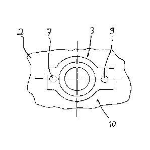
In Fig. 1 a shoe 1 being a sports shoe can be seen which has an upper 2 and a
sole 11.
The lacing of the shoe 1 takes place by means of a rotating closure 3 (i. e.
of a central
fastener), wherein by rotating of a tensioning roller 5 at least one
tensioning element 4 is
winded on the tensioning roller 5 and thus the upper 2 is tensioned and laced
respectively
at the foot of the wearer of the shoe 1.
The rotating closure 3 is arranged on the instep 10 of the shoe 1. The axis of
rotation of
the tensioning roller is thereby perpendicular to the region of the instep 10
of the shoe 1.
Accordingly, a convenient access to the rotating closure 3 is ensured for the
user of the
shoe who must only actuate corresponding buttons, namely a closing button 7
and an
CA 03004612 2018-05-08
8
opening button 9 (s. figure 2), for opening and closing of the rotating
closure because the
rotating closure 3 is electric motor operated. The electric motor 6 is
indicated which is
required for that; it can drive the tensioning roller 5 via a ¨ not depicted ¨
gear. In the
embodiment the axis of rotation of the electric motor 6 is arranged
horizontally and
transverse to the longitudinal direction of the shoe.
The actuation of the electric motor 6 for the opening and the closing of the
rotating
closure 3 is initiated by a control system 8 which is correspondingly also
connected with
the closing button 7 and the opening button 9.
For closing of the shoe 1 the user proceeds as follows:
When he wants to put on the shoe at his foot with a first (low) tensioning
force level he
taps once onto the closing button 7. This tap impulse is denoted in figure 3a
with the
arrow. The control system 8 registers the tap impulse and waits a waiting time
tw to find
out if further tap impulses follow by the user. If this is not the case the
software which is
stored in the control system 8 knows that the user wanted to give a first
closing signal S1
which corresponds to said first tensioning force level.
Accordingly the electric motor 6 is driven until a first predetermined maximum
value for
the motor current is given, for example 1.5 A.
When the user wants to put on the shoe at his foot with a second (medium)
tensioning
force level he taps twice onto the closing button 7. This sequence of tap
impulses is
denoted in figure 3b with the arrows. The control system 8 registers again the
tap
impulses wherein intended double impulses ¨ as shown in figure 3b ¨ can be
identified
by the fact that they follow within a predetermined following time tF.
Otherwise the
control system waits again the waiting time tw after the last identified tap
impulse to find
out if still further tap impulses follow by the user. If this is not the case
the software
= ,
CA 03004612 2018-05-08
9
which is stored in the control system 8 knows that the user wanted to give
said second
closing signal S2 which corresponds to said second tensioning force level.
Accordingly the electric motor 6 is driven now until a second predetermined
maximum
value for the motor current is given which is higher than the first value, for
example 2.5
A.
The analogue applies, when the user wants to put on the shoe at his foot with
a third
(high) tensioning force level. He taps in this case three times onto the
closing button 7.
.. This sequence of tap impulses is denoted in figure 3c with the arrows. The
control
system 8 registers again the tap impulses wherein intended multiple impulse ¨
as shown
in figure 3c ¨ can be identified by the fact that the time distance between
two tap
impulses is within the predetermined following time tF. Otherwise the control
system
waits again the waiting time tw after the last identified tap impulse to find
out if still
.. further tap impulses follow by the user. If this is not the case the
software which is stored
in the control system 8 knows that the user wanted to give said third closing
signal S3
which corresponds to said third tensioning force level.
Accordingly the electric motor 6 is driven now until a third predetermined
maximum
value for the motor current is given which is higher than the second value,
for example
3.5 A.
Accordingly the possibility exists by the proposed proceedings to reach a
selective
tensioning force level by different closing signals Si, S2 and S3
respectively.
The user needs not ¨ as in the state of the art ¨ actuate the closing button 7
for a longer
time; rather it is sufficient that he gives the respective sequence of
impulses.
Furthermore, the user can thereby directly obtain a tensioning force level
which fits to
his desires without adjusting the same by a respective long pressing of the
closing
button.
v.
CA 03004612 2018-05-08
When the shoe fits at least with the first tensioning force level at the foot
of the user and
when the user presses once onto the closing button 7, when he thus gives a
single tap
impulse onto the button, the next tensioning force level can be automatically
obtained
5 according to a further embodiment, thus from the first into the second
tensioning force
level or from the second into the third tensioning force level. This is
mentioned above
when reciting the further closing signal which is applied in the given case by
the user to
the closing button.
10 For opening of the shoe, i. e. for releasing of the tensioning element
4, the user presses
once onto the opening button 9. The electric motor 6 drives then into the
completely
tensionless state which can detected by a respective rotation angle sensor at
the
tensioning roller 5.
= ,
CA 03004612 2018-05-08
11
LIST OF REFERENCES
1 Shoe
2 Upper
3 Rotating closure
4 Tensioning element
5 Tensioning roller
6 Electric motor
7 Closing button
8 Control system
9 Opening button
10 Instep
11 Sole
S1 First closing signal
S2 Second closing signal
S3 Third closing signal
S4 Further closing signal
tw Waiting time
tF Following time