Note: Descriptions are shown in the official language in which they were submitted.
CA 03005352 2018-05-15
- 1 -
ELECTRO-CHEMICAL MODULE
The present invention relates to an electro-chemical
module, in particular to a fuel cell module, which has a
porous plate-shaped metallic carrier substrate having a
gas-permeable central region and a peripheral region
surrounding the central region; a layered construction
having at least one electro-chemically active layer which
is disposed in the central region on a first side of the
carrier substrate; at least one metallic gas-tight
housing part which by way of a welded connection is
connected to the peripheral region of the carrier
substrate; and a gas-tight zone extending from the
layered construction up to the gas-tight housing part.
The electro-chemical module according to the invention is
employable inter alia as a high-temperature fuel cell or
as a solid oxide fuel cell (SOFC), as a solid oxide
electrolyser cell (SOEC), and as a reversible solid oxide
fuel cell (R-SOFC). A mechanically supportive component
which may be formed, for example, by one of the electro-
chemically active layers of the layered construction,
such as, for example, by an electrolyte, an anode, or a
cathode of the functional layers which in this instance
are configured in a correspondingly thick manner, or by a
component which is configured so as to be separate by one
of these functional layers, such as, for example, by a
ceramic or metallic carrier substrate, is required for
the layers of the layered construction that are
configured so as to be comparatively thin. The present
invention relates to the latter concept having a
separately configured metallic carrier substrate which
forms the supporting function for the layers of the
layered construction. Metal substrate supported systems
(MSC - metal supported cells) of this type in terms of
CA 03005352 2018-05-15
- 2 -
thermal and redox cyclability and in terms of mechanical
stability are advantageous. In that the electrolyte, of
which the electrical resistance drops as the thickness is
reduced and the temperature is increased, in the case of
MSCs may be configured so as to be comparatively thin
(for example, having a thickness in the range of 2 to
pm, preferably in the range of 3 to 5 pm), MSCs may be
operated at a comparatively low operating temperature of
approx. 600 C to 800 C (while SOFCs in some instances are
10 operated at operating temperatures of up to 1000 C). By
virtue of their specific advantages, MSCs are suitable in
particular for mobile applications such as, for example,
for supplying electrical power to passenger motor
vehicles or to commercial motor vehicles (APU - auxiliary
power unit).
In comparison with fully ceramic systems, these metal-
ceramic MSC systems (i.e. a metallic carrier substrate
having at least in proportions a ceramic layered
construction) are distinguished by significantly reduced
material costs and by new potentials in terms of stack
integration in that the metallic carrier substrate
enables bonding by means of soldering/brazing and welding
processes, which are cost-effective and very durable
connection techniques. In the context of stack
integration, the individual metal substrate supported
cells specifically need to be connected to respective
(metallic) housing parts (for example, a sheet-metal
frame plate, an interconnector, etc.), disposed on top of
one another in a stack, and to be interconnected
electrically in series. In the case of the individual
cells of the stack, the housing parts provide the
respective dedicated gas supply of the process gases, in
the case of a fuel cell meaning the supply of the fuel to
the anode and of the oxidation means to the cathode, and
CA 03005352 2018-05-15
- 3 -
the discharge of the gases which are created in the
electro-chemical reaction. Furthermore, the electrical
interconnection of the individual cells of a stack in
series is performed by way of these housing parts.
The reliable gas-tight separation of the two process-gas
spaces which in relation to one cell are configured on
either side of the electrolyte is essential for the
functionality of the individual cells. A considerable
challenge in particular lies in the bonding of the metal
substrate supported cell to the contiguous housing
part(s), as the transition region from the layered
construction, the electrolyte establishing the process-
gas separation in the region of said layered
construction, up to the contiguous housing part(s) is to
be configured in a gas-tight manner (at least in respect
of the process gases and the gases created), this gas-
tightness having to be guaranteed for extended durations
of employment, with mechanical stresses and temperature
variations arising.
A method for manufacturing a fuel cell, in which a
metallic carrier substrate having gas-passage openings
which are provided in the peripheral region is obtained
in that a planar porous body is powder-metallurgically
manufactured, the peripheral region of the body by
uniaxial pressing or rolling is compressed up to reaching
gas-tightness, and is provided with gas-passage openings,
is known from EP 2 174 371 Bl. The layered construction
having electro-chemically active layers is applied in the
central porous region of the metallic carrier substrate.
An assembly in which a metallic carrier substrate is
configured so as to be gas-permeable and has a gas-tight
zone which extends through the entire thickness of the
CA 03005352 20113--15
v
r . *
- 4 -
substrate and is fixed to a housing by welding and/or
soldering/brazing is described in EP 1 278 259 Bl.
Accordingly, the object of the present invention lies in
providing in a cost-effective manner an electro-chemical
module having a metallic carrier substrate and a layered
construction having at least one electro-chemically
active layer, which is disposed in a central porous
region of the carrier substrate, wherein a transition
region between the layered construction and a housing
part which is contiguous to the carrier substrate is
configured so as to be gas-tight at least to the process
gases and to the gases created, this gas tightness being
guaranteed over long durations of employment, even in the
case of mechanical stresses and temperature variations.
This object is achieved by an electro-chemical module
according to Claim 1, and by a method for manufacturing
an electro-chemical module, according to Claim 15.
Advantageous refinements of the invention are stated in
the dependent claims.
According to the present invention, the electro-chemical
module has a porous plate-shaped metallic carrier
substrate having (in relation to the plane of primary
extent thereof) a gas-permeable central region and a
peripheral region surrounding the central region;
a layered construction having at least one, in particular
at least two, electro-chemically active layer(s), which
layered construction is disposed in the central region on
a first side of the carrier substrate; at least one
metallic gas-tight housing part which by way of a welded
connection is connected to the peripheral region of the
carrier substrate; and a gas-tight zone extending from
the layered construction (at least) up to the gas-tight
CA 03005352 2018-05-15
- 5 -
housing part. The gas-tight zone here has a gas-tight
surface portion which extends superficially from the
layered construction on the first side (i.e. the side
facing the layered construction) of the carrier substrate
(at least) up to the welded connection; and the welded
connection by which the gas-tight surface portion is
connected in a gas-tight manner to the housing part and
the welding zone of which, proceeding from the first
side, in the thickness direction extends only through
part of the thickness of the carrier substrate to an
opposite second side of the carrier substrate.
In that, according to the invention, the gas-tight zone
extends only superficially on the first side of the
carrier substrate it is possible according to the present
invention for a carrier substrate which is powder-
metallurgically manufactured in an integral manner and
which in the peripheral region is not to be compressed to
reach gas tightness to be used. Specifically in the case
of materials which are difficult to press, such as formed
by chromium-based alloys or by alloys which have a
significant proportion of chromium, considerably lower
pressing forces are required on account thereof,
manufacturing costs being saved and the proportion of
waste being reduced as a result. Furthermore, more
constant material properties are achieved along the plane
of primary extent of the carrier substrate, on account of
which the risk of fissuring and warping, in particular at
high temperature variations and/or mechanical stresses is
reduced. In that the welding zone, proceeding from the
first side, extends only through part of the thickness of
the carrier substrate, the welded connection also only
initiates a comparatively minor variation in the material
properties within the carrier substrate. Accordingly, it
is ensured that the advantageous material properties of
1
' CA 03005352 2018-05-15
'
- 6 -
the carrier substrate that are obtained by way of the
powder-metallurgical manufacturing process are largely
maintained. By contrast, if the welding zone (which is
configured so as to be gas tight) would extend through
the entire thickness of the carrier substrate, a
considerably higher energy input would be required during
welding of the carrier substrate by virtue of the
comparatively large welding zone required. A design
embodiment of this type would not only lead to increased
production costs but also to greater warping of the
components, to a coarsening of the grain in the
microstructure of the regions contiguous to the welding
zone which has a detrimental effect on the material
properties, and to the risk of fissuring or even of
rupture in the case of mechanical and/or thermal stress
in the region of the welding zone.
Apart from the preferred application as a high-
temperature fuel cell or as a solid oxide fuel cell
(SOFC), the electro-chemical module according to the
invention is also employable as a solid oxide
electrolyser cell (SOEC), and as a reversible solid oxide
fuel cell (R-SOFC). The construction and the functioning
of metal substrate supported high-temperature fuel cells
(SOFCs), as are implementable using the electro-chemical
module according to the invention, will be discussed
hereunder. Such metal substrate supported SOFCs form the
preferred application for the electro-chemical module
according to the invention. A metal substrate supported
cell (MSC) is composed of a porous plate-shaped metallic
carrier substrate having a preferred thickness in the
range of 170 pm to 1.5 mm, in particular in the range of
250 pm to 800 pm, on which in a gas-permeable central
region a layered construction having the anode, the
electrolyte, and the cathode as electro-chemically active
CA 03005352 2018-05-15
,
,
'
'
- 7 -
layers and optionally having further layers (for example,
diffusion barriers of, for example, cerium-gadolinium
oxide or lanthanum-chromium oxide, etc., between the
carrier substrate and the anode, a diffusion barrier of,
for example, cer-gadolinium oxide between the electrolyte
and the cathode) is applied. In the case of the electro-
chemical module according to the invention, not all
electro-chemically active layers need to be applied here;
rather, the layered construction may also have only one
electro-chemically active layer (for example, the anode),
preferably two electro-chemically active layers (for
example, the anode and the electrolyte), the further
layers, in particular those for completing an electro-
chemical cell, being applied only subsequently. The
application of the layers of the layered stack is
preferably performed by means of PVD (physical vapour
deposition), for example by sputtering, and/or by means
of thermal coating methods, for example flame spraying or
plasma spraying, and/or by wet-chemical methods, such as,
for example, screen printing, wet powder coating, etc.,
wherein a plurality of these methods may also be employed
in combination in order for the entire layered
construction of an electro-chemical cell to be
implemented. Preferably, the anode is that electro-
chemically active layer that is next to the carrier
substrate, while the cathode is configured on that side
of the electrolyte that faces away from the carrier
substrate. Alternatively, however, a reversed arrangement
of the two electrodes is also possible.
Both the anode (formed from a composite composed of
nickel and zirconium dioxide fully stabilized with
yttrium oxide, for example) as well as the cathode
(formed from perovskites with mixed conductivity, such as
(La,Sr)(Co,Fe)03, for example) are configured so as to be
CA 03005352 213113--15
- 8 -
gas-permeable. A gas-tight solid electrolyte from a solid
ceramic material from metal oxide (for example, from
zirconium dioxide fully stabilized with yttrium oxide),
which is conductive to oxygen ions but not to electrons,
is configured between the anode and the cathode.
Alternatively, the solid electrolyte may also be
conductive to protons but not to electrons, this relating
to the younger generation of SOFCs (for example, a solid
electrolyte from metal oxide, in particular from barium-
zirconium oxide, barium-cerium oxide, lanthanum-tungsten
oxide, or lanthanum-niobium oxide). During operation of
the SOFC the anode is supplied with fuel (for example,
hydrogen or conventional hydrocarbons such as methane,
natural gas, biogas, etc., optionally in a complete or a
partially prereformed state), said fuel in the anode
being oxidized in a catalytic manner while discharging
electrons. The electrons are diverted from the fuel cell
and by way of an electrical consumer flow to the cathode.
An oxidizing means (for example, oxygen or air) is
reduced by absorbing the electrons at the cathode. The
electrical circuit is closed in that in the case of an
electrolyte which is conductive to oxygen ions, the
oxygen ions which are created at the cathode by way of
the electrolyte flow to the anode and react with the fuel
on the respective interfaces.
In the case of a solid oxide electrolyser cell (SOEC) in
which a redox reaction is forced while employing an
electric current, such as for example a conversion of
water to hydrogen and oxygen, the metal substrate
supported cell (MSC) is configured so as to correspond to
the construction explained here above. Here, the layer
which here above has been described with reference to the
SOFC as the anode, corresponds to the cathode, and vice-
CA 03005352 2018-05-15
- 9 -
versa. A reversible solid oxide fuel cell (R-SOFC) is
operatable both as an SOEC as well as an SOFC.
In the present context, "gas tight" means in particular
that the leakage rate at sufficient gas tightness as a
standard is < 10-3 hPa*dm3/cm2s (hPa: hectopascal, dm3:
cubic decimetre, CM2 : square centimetre, s:
second)(measured under air using the pressure-increase
method and the measuring apparatus of the Dr. Wiesner
company, Remscheid, type: Integra DDV, at a pressure
differential dp = 100 hPa). A gas tightness of this type
is implemented in particular in the region of the gas-
tight zone and in the region of the layered construction.
The peripheral region is disposed in particular in an
encircling manner around the gas-permeable central
region. The at least one housing part which, for example,
may be configured as a sheet-metal plate part from steel
types having a high chromium content (commercially
available, for example, under the trade names Crofer 22
H, Crofer0 22 APU, ZMGC) 232L), preferably likewise
extends in an encircling manner around the peripheral
region and along the entire circumference of the
peripheral region is connected to the latter by way of
the welded connection. The welding zone which is formed
by a fused structure and which according to the invention
extends only through part of the thickness of the carrier
substrate is identifiable, for example, by means of a
micrograph which is produced in the cross section through
the welded connection under an illuminated microscope or
under a scanning electron microscope (SEM).
According to one refinement, the central region and the
peripheral region are configured in a monolithic manner,
that is to say integrally, this being understood to mean
CA 03005352 2018-05-15
- 10 -
that these are not a plurality of interconnected
components, optionally also interconnected by way of a
materially integral connection (for
example,
soldering/brazing, welding, etc.). According to one
refinement, the carrier substrate is integrally
manufactured by powder metallurgical means from a
material combination which is based on Cr (chromium)
and/or Fe (iron), that is to say that the proportion of
Cr and of Fe in total are at least 50% of weight. The
powder-metallurgical and integral manufacture is
identifiable by means of the microstructure of the
carrier substrate which below the gas-tight zone across
the entire plane of primary extent thereof has a typical
sintered structure in which the individual grains,
depending on the degree of sintering, are interconnected
by more or less pronounced sintering necks. In
particular, the proportion of Cr and of Fe in total is at
least 80% of weight, preferably at least 90% of weight.
In particular, the carrier substrate may be manufactured
according to AT 008 975 Ul, and thus be composed of an
Fe-based alloy having Fe >50% of weight, and 15 to 35% of
weight Cr; 0.01 to 2% of weight of one or a plurality of
elements from the group Ti (titanium), Zr (zirconium), Hf
(hafnium), Mn (manganese), Y (yttrium), Sc (scandium),
rare-earth metals; 0 to 10% of weight Mo (molybdenum)
and/or Al (aluminium); 0 to 5% of weight of one or a
plurality of metals from the group Ni (nickel), W
(tungsten), Nb (niobium), Ta (tantalum); 0.1 to 1% of
weight 0 (oxygen); the remainder being Fe and impurities,
wherein at least one metal from the group Y, Sc, rare-
earth metals, and at least one metal from the group Cr,
Ti, Al, Mn form a mixed oxide. In order for the carrier
substrate to be formed, a powder fraction having a
particle size <150 pm, in particular <100 pm is
preferably used. In this way, the surface roughness may
CA 03005352 20113--15
- 11 -
be kept sufficiently low so as to guarantee ready coating
capability for functional layers. Furthermore, the
particle size is to be chosen to be smaller, the thinner
the carrier substrate is to be configured. After the
sintering process, the porous substrate has a porosity of
preferably 20 to 60%, in particular of 40 to 50%. Said
porous substrate preferably has a thickness in the range
of 170 pm to 1.5 mm, in particular in the range of 250 pm
to 800 pm.
According to one refinement, the carrier substrate below
the gas-tight surface portion (that is to say in the
direction towards the second side) and below the welding
zone of the welded connection is configured so as to be
porous. In particular, said carrier substrate in this
porous portion is still gas-permeable. In this manner,
largely identical material properties of the carrier
substrate, from the porous central region which
mandatorily is to be configured as gas-permeable, to and
including the peripheral region of said carrier
substrate, are achieved. Furthermore, a non-gradual
transition which carries the risk of material weaknesses
and material fatigue, such as fissuring, is avoided. In
the case of a powder-metallurgically manufactured carrier
substrate it is consequently not necessary for the
peripheral region to be compressed in a gas-tight manner
as a solid material, this being advantageous in view of
the difficult pressing and processing capabilities of
powders containing Cr. According to one refinement, the
carrier substrate in the porous portion of the peripheral
region (that is to say except for the regions of the gas-
tight zone) has a porosity which in relation to the
porosity of the central region is reduced. In the case of
a powder-metallurgically manufactured carrier substrate,
this may be performed, for example, by compressing the
CA 03005352 2018-05-15
,
, .
- 12 -
peripheral region, in particular by uniaxial pressing or
by profiled rolling. Preferably a continuous transition
between the central region and the peripheral region is
manufactured during the compressing process, on account
of which tensions arising in the carrier substrate are
avoided. Such reduced porosity which is accompanied by
increased density is advantageous for configuring the
gas-tight surface portion. If the latter is formed by a
cover layer to be applied thereon, for example, the gas-
tight configuration thereof is enabled by the reduced
porosity and the adherence thereof is improved. However,
if the surface portion is manufactured by superficial
fusing, the volumetric variation which arises in a
localized manner is minimized by the reduced porosity.
According to one refinement, the carrier substrate in the
porous portion of the peripheral region has a porosity in
the range of 3% to 20% (both inclusive), preferably in
the range of 4% to 12% (both inclusive). Gas tightness is
typically not yet provided within these ranges of
porosity.
According to one refinement, the welding zone extends
from the first side in the thickness direction to the
second side up to a depth t of 20% t 80% of the
thickness d which the carrier substrate has in the
peripheral region. Preferably, the depth t is
30% -- t __ 50% of the thickness d. Within these ranges, a
connection of sufficiently high strength between the
housing part and the carrier substrate is achieved, on
the one hand, and the energy input during welding is kept
low, on the other hand, the carrier substrate at least in
portions remaining in the original structure thereof.
According to one refinement, that housing portion of the
housing part that is connected by the welded connection
CA 03005352 2018-05-15
, . .
'
- 13 -
is disposed so as to overlap the peripheral region of the
carrier substrate, and disposed on the first side of the
carrier substrate; in particular, the housing portion in
the overlapping region bears in a planar manner on the
peripheral region of the carrier substrate. By way of a
design embodiment of this type, the mechanical stability
of the welded connection between the housing part and the
carrier substrate is increased,
simultaneously
facilitating the welding procedure.
According to one refinement, the welding zone in the
thickness direction extends completely through the
housing part and only partially into the carrier
substrate. In particular, the welding zone extends so as
to be substantially perpendicular to the plane of primary
extent of the carrier substrate, or along the thickness
direction, respectively. This type of welded connection
in the case of an overlapping arrangement between the
housing part and the peripheral region of the carrier
substrate is particularly simply manufacturable in the
overlapping region. According to one refinement, the
welding zone is configured on the periphery of the
carrier substrate and/or on the periphery of the housing
part, and in the thickness direction extends only through
part of the thickness of the housing part. In particular,
said welding zone, in the thickness direction extends up
to a depth T of 20%
T __ 80% of the thickness of the
housing part in the region to be connected, the depth T
preferably being 30%
T __ 50% of this thickness. In this
way, the energy input during welding may be kept
particularly low, on account of which the risk of warping
of the components is reduced even further.
According to one refinement, the housing part is
configured in a frame-type manner, extending in an
CA 03005352 2018-05-15
- 14 -
encircling manner around the peripheral region of the
carrier substrate. In this manner, encircling gas-tight
bonding of the carrier substrate assembly, mechanical
mounting of the latter, and electrical contact of said
carrier substrate assembly are guaranteed in a reliable
and mechanically stressable manner. According to one
refinement, the housing part is a sheet-metal frame plate
which is provided with gas-passage openings, the sheet-
metal frame plate in the region of the external periphery
thereof being connected to an interconnector, this being
in particular a gas-tight connection (for example, a
welded connection, optionally also having an overlapping
region between the sheet-metal frame plate and the
interconnector). The gas-passage openings here serve for
supplying and discharging the process gases. The
interconnector which likewise is part of the housing is
disposed in the stack between two carrier substrate
assemblies which in each case are disposed on top of one
another and which each have an electro-chemical cell.
Said interconnector, by means of a structure (for
example, burl-shaped, rib-shaped, or wave-shaped) on
either side establishes the supply and discharge of the
process gases across substantially the entire area of the
electro-chemical cell, or of the central region of the
carrier substrate, respectively. Furthermore, adjacent
carrier substrate assemblies which each have one electro-
chemical cell are electrically intercontacted in series
by way of said interconnector. Preferably, the
interconnector is also formed by a correspondingly formed
metallic sheet-metal plate part. A gas-tight gas space on
the one side of the electrolyte, in particular on that
side that faces the associated carrier substrate, is thus
achieved in that the carrier substrate assembly is bonded
to the frame-shaped housing part in an encircling and
gas-tight manner, the frame-shaped housing part in turn
CA 03005352 2018-05-15
- 15 -
being bonded to the interconnector in an encircling and
gas-tight manner. This means that a type of housing is
formed by the frame-shaped housing part and by the
interconnector, and that a gas-tight process-gas space is
implemented in this way. Sealing and establishing the
respective desired routing of gas in the region of the
gas-passage openings is typically obtained by separate
inserts, seals, and by the targeted application of
sealing compound (for example, glass solder).
A second alternative lies in that the carrier substrate
is bonded directly in a gas-tight manner to the
interconnector which after all likewise forms a housing
part and can be configured so as to correspond to the
features which here above have been described with
reference to the interconnector. In the case of this
variant, the peripheral region of the carrier substrate
which is configured in a correspondingly larger manner,
would assume the function of the frame-shaped housing
part, as has been described above; in particular, the
gas-tight surface portion would extend from the layered
construction up to the welded connection by way of which
the peripheral region is connected to the interconnector
(housing part). Preferably, the gas-passage openings
which by means of punching, cutting, embossing, or
comparable methods, for example, are incorporated into
the peripheral region, would also be provided in the
peripheral region. Preferably, the (for example,
cylindrical) walls of the gas-passage openings, which are
configured within the carrier substrate, are also
configured so as to be gas-tight. In particular, the gas-
tight walls of the gas-passage openings are contiguous in
a gas-tight manner to the gas-tight surface portion
which, after all, is configured in an encircling manner
around the gas-passage openings, on account of which
CA 03005352 2018-05-15
=
,
- 16 -
routing of the process gas without leakage is guaranteed.
A gas-tight configuration of the walls of the gas-passage
openings is achieved in that, for example, these gas-
passage openings are incorporated by means of thermal
processes such as laser-beam cutting, electron-beam
cutting, ion-beam cutting, water-jet cutting, or
frictional edge cutting, as these processes lead to
superficial fusing of the carrier substrate material, on
account of which after solidification a gas-tight portion
which extends superficially along the walls and which has
a melt phase of the carrier substrate material, and in
particular is formed completely from a melt phase of the
carrier substrate material, is obtained.
A third variant lies in that the peripheral region of the
carrier substrate in the manner as has been illustrated
here above is provided with gas-passage openings, and
outside the gas-passage openings is bonded to a frame-
shaped housing part in an encircling and gas-tight
manner. In this instance, the frame-shaped housing part
is bonded to an interconnector in an encircling and gas-
tight manner, as has been described here above with
reference to the first variant.
According to one refinement, the gas-tight surface
portion has an electrolyte which is part of the layered
construction and on the first side of the carrier
substrate extends beyond the layered construction. In
particular, said electrolyte extends up to the welded
connection. Said electrolyte typically has a thickness in
the range of 2 to 10 pm, preferably of 3 to 5 pm. Said
electrolyte may also extend beyond the welded connection,
in particular up to an external periphery of the carrier
substrate (the heat transfer during establishment of the
welded connection at the stated thickness range of 3 to
CA 03005352 2018-05-15
,
- 17 -
pm is not appreciably influenced by the electrolyte).
In that the electrolyte has the required gas-tight
properties and is required for implementing the layered
construction, it is advantageous to employ said
5 electrolyte for implementing the entire gas-tight surface
portion, or else only a part thereof.
According to one refinement, the gas-tight surface
portion has a superficial gas-tight portion of the
carrier substrate, which gas-tight portion is formed from
the carrier substrate material and comprises a melt phase
of the carrier substrate material. This is achieved in
particular by means of a surface post-treatment step
leading to the formation of a melt phase of the material
of the carrier substrate in a region of the carrier
substrate that is close to the surface. Such a surface
post-treatment step may be obtained by localized
superficial fusing of the porous carrier substrate
material, that is to say by brief localized heating to a
temperature which is higher than the melting temperature,
and may be performed by means of mechanical, thermal, or
chemical method steps, for example by means of abrading,
blasting, or applying laser beams, electron beams, or ion
beams. Preferably a superficial portion which has the
melt phase is obtained by impacting bundled beams of
high-energy photons, electrons, ions, or of other
suitable focussable energy sources, onto the surface of
the peripheral region until a specific impact depth has
been reached. By way of localized fusing and of rapid
cooling after fusing, a modified metallic structure
having imperceptible Or extremely minor residual
porosity, respectively, is formed in this region. This
modified structure which has a melt phase, is readily
distinguishable from that of the carrier substrate, which
is distinguished by a sintered structure, for example in
CA 03005352 2018-05-15
, *
- 18 -
an image from an illuminated microscope or an image from
a scanning electron microscope (SEM) of a micrograph of a
cutting face through the carrier substrate that is
configured along the thickness direction. Fusing may be
performed once or else multiple times in sequence. The
fusing depth here is to be adapted to the requirement of
gas tightness; a fusing depth of at least 1 pm, in
particular of 15 pm to 50 pm (both
inclusive),
particularly preferably of 20 pm to 40 pm
(both
inclusive), has been found to be suitable. Therefore, the
superficial portion which has the melt phase, measured
from the surface of the carrier substrate, extends by
this fusing depth into the carrier substrate. Other
phases, for example, amorphous structures, may also be
present in the superficial portion which has the melt
phase alongside the melt phase. Particularly preferably,
that superficial portion that has the melt phase is
formed completely from the melt phase of the carrier
substrate material. The fusing process leads to a very
smooth surface of low surface roughness. This permits
ready coating capability for functional layers such as an
electrolyte layer which, proceeding from the layered
construction, preferably extends at least across part of
that superficial portion that has the melt phase. Such a
surface post-treatment step is described in
WO 2014/187534 Al, for example.
According to one refinement, the gas-tight surface
portion has a gas-tight sealing compound which is applied
on the carrier substrate such as, for example, a glass
solder, a metal solder, or an inorganic paste which
optionally also only cures during operation of the
electro-chemical module.
CA 03005352 2018-05-15
,
'
'
- 19 -
The gas-tight surface portion may also be formed by a
plurality of gas-tight portions, in particular from a
combination of an electrolyte, of a gas-tight superficial
portion of the carrier substrate that is formed from the
carrier substrate material and has a melt phase, and/or
of a gas-tight sealing compound. In relation to the plane
of primary extent of the plate-shaped carrier substrate,
these portions may also be configured so as to be on top
of one another in multiple layers; optionally, however,
such overlapping regions may also be provided only in
portions.
The present invention furthermore relates to a method for
manufacturing an electro-chemical module, the method
having the following steps:
A) powder metallurgical manufacturing of a porous
plate-shaped metallic carrier substrate which at
least in a central region which is surrounded by a
peripheral region is configured so as to be gas-
permeable;
B) gas-tight bonding of a layered construction to at
least one metallic gas-tight housing part on a
first side of the carrier substrate,
in that the layered construction comprising at
least one electro-chemically active layer in the
central region is applied on the first side of the
carrier substrate,
in that the at least one metallic gas-tight
housing part by way of a welded connection is
connected to the peripheral region of the carrier
substrate in such a manner that the welding zone,
proceeding from the first side, in the thickness
direction extends only through part of the
thickness of the carrier substrate to an opposite
second side of the carrier substrate, and
CA 03005352 2018-05-15
- 20 -
in that a gas-tight surface portion which extends
superficially from the layered construction on the
first side of the carrier substrate up to the
welded connection is configured.
By way of the method according to the invention, the
identical advantages as have been described here above
with reference to the electro-chemical module according
to the invention are substantially achievable. The
refinements and optional additional features which have
been described here above with reference to the electro-
chemical module are also implementable in a corresponding
manner in the context of the presently claimed
manufacturing method, leading to the abovementioned
advantages. The individual steps which are to be carried
out in the context of "gas-tight bonding" (cf. step B))
here may be carried out in a different sequence. If the
gas-tight surface portion is to extend beyond the welded
connection in the direction towards the external
periphery of the carrier substrate, the gas-tight surface
portion is then preferably to be configured prior to the
housing part by way of a welded connection being
connected to the peripheral region of the carrier
substrate.
In order for the porosity of the various regions of the
carrier substrate to be determined, polished cross
sections which are perpendicular to the plane of primary
extent of the plate-shaped carrier substrate are made in
that parts are sawn out of the carrier substrate by means
of a diamond-wire saw, these parts are fixed in an
embedding means (for example in epoxy resin), and after
curing are polished (using successively finer sandpaper).
Subsequently, the specimens are polished using a
polishing suspension, and finally are electrolyte-
CA 03005352 2018-05-15
- 21 -
polished. These specimens are analysed by means of a
scanning electron microscope (SEM) and a ESE (back-
scattered electrons) detector (ESE detector and/or 4-
quadrant-ring detector). As a scanning electron
microscope, the field emission apparatus "Ultra Plus 55"
of the Zeiss company was used here. The SEM image within
a measured area to be evaluated is in each case evaluated
in quantitative terms by means of stereological methods
(software used: "Leica QWin"), wherein attention is paid
to as homogenous a fragment as possible of the part of
the carrier substrate being present within the measured
area to be evaluated. The proportion per unit area of
pores in relation to the entire measured area to be
evaluated is determined in the context of the measurement
of porosity. This proportion per unit area simultaneously
corresponds to the porosity in % of the volume of pores.
Those pores that are only partially within the measured
area to be evaluated are not considered in the case of
the measuring method. The following settings were used
for the SEM image: tilting angle: 00, acceleration
voltage of 20 kV, operating spacing of approx. 10 mm, and
a magnification of 250 (as per the apparatus), resulting
in a horizontal picture edge of approx. 600 pm. Here,
particular value was placed on very good image sharpness.
Further advantages and expediencies of the invention are
derived by means of the following description of
exemplary embodiments with reference to the appended
figures in which, for reasons of visualizing the present
invention, the proportions are not always provided to
scale.
In the figures:
CA 03005352 2018-05-15
- 22 -
Fig. 1: shows a stack having two electro-chemical
modules according to the present
invention, in the cross section;
Figs. 2a-2h: show an electro-chemical module according
to the present invention, in the cross
section, connected to an interconnector,
having in each case different variants of
the gas-tight zone;
Fig. 3: shows a metallic carrier substrate having
integrated gas-passage openings, in a
perspective view;
Fig. 4: shows an SEM image of the peripheral
region of a metallic carrier substrate in
the polished cross section, having carrier
substrate material superficially fused
thereto;
Figs. 5a-5b: show SEM images of the surface of the
peripheral region of a metallic carrier
substrate prior to (Fig. 5a) and post
(Fig. 5b) superficial fusing; and
Figs. 6a-6b: show illuminated microscope images of two
electro-chemical modules according to the
invention in the region of the welding
zone in the polished cross section, once
having a comparatively low (Fig. 6a) and
once having a comparatively great (Fig.
6b) penetration depth of the welding zone.
Fig. 1 in a schematic illustration shows a stack (2)
having two electro-chemical modules (4) according to the
CA 03005352 2018-05-15
*
- 23 -
present invention, each being connected to an
interconnector (6). The electro-chemical modules (4) each
have a powder-metallurgically manufactured porous plate-
shaped metallic carrier substrate (8) having a gas-
permeable central region (10) and a peripheral region
(12) which in relation to the central region is further
compressed, and a metallic sheet-metal frame plate (14)
which is placed onto a first side (13) of the carrier
substrate (8) and which in the overlapping region of the
inner frame region (16) thereof by way of an encircling
welded connection (18) is connected to the peripheral
region (12) of the carrier substrate (8). The peripheral
region (12) here has a lower porosity than the central
region (10), the former however still being configured so
as to be gas-permeable. On a second side (20) of the
carrier substrate (8), the interconnector (6) which in
the central region thereof has a ribbed structure (22),
in each case bears in portions on the carrier substrate
(8), wherein the interconnector (6) and the sheet-metal
frame plate (14), each by way of the peripheral regions
thereof, bear on one another in an encircling manner and
are interconnected in an encircling manner by way of a
welded connection (24). The viewing direction in Fig. 1
here runs along the direction of extent of the ribbed
structure (22).
The configuration of the layered construction and of the
gas-tight zone hereunder will be explained with reference
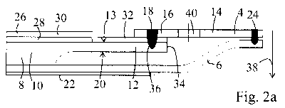
to Fig. 2a which schematically shows the electro-chemical
module (4) according to the present invention in the
cross section and having a higher degree of detail in the
region of the layered construction and of the gas-tight
zone (in proportions departing from those of Fig. 1), but
presently in the viewing direction which is transverse to
the direction of extent of the ribbed structure (22) of
CA 03005352 2018-05-15
'
. '
- 24 -
the interconnector (6), said electro-chemical module (4)
being connected to the interconnector (6). The same
reference signs as in Fig. 1 are used for identical or
equivalent components. A layered construction (26) which
presently has an anode (28) which is disposed on the
carrier substrate (8), and an electrolyte (30) which is
disposed on the anode (28), is applied in the central
region (10) on a first side of the carrier substrate (8),
a diffusion barrier layer which is typically provided
between the anode (28) and the carrier substrate (8) not
being illustrated. A gas-tight zone (32) which extends
from the layered construction (26) up to the sheet-metal
frame plate (14) is formed in that the gas-tight
electrolyte (30) is extended beyond the central region
(10) and the anode (28) on the first side (13) along the
surface of the carrier substrate (8) into the overlapping
region with the sheet-metal frame plate (14) (presently
even up to an external periphery (34) of the carrier
substrate (8)). An encircling gas-tight transition from
the electrolyte (30) to the sheet-metal frame plate (14)
is established by the welded connection (18). Proceeding
from the first side (13) in the thickness direction (38),
a welding zone (36) of the welded connection extends in
the direction towards the opposite second side (20) only
through part of the thickness of the carrier substrate
(8). The direction which is perpendicular to the plane of
primary extent of the plate-shaped carrier substrate (8)
is referred to here as the thickness direction (38). A
gas-passage opening (40) which is configured in the
sheet-metal frame plate (14) is furthermore illustrated
in Fig. 2a.
Further embodiments of the present invention will be
explained hereunder with reference to Figs. 2b to 2h, the
manner of illustration largely corresponding to that of
CA 03005352 2018-05-15
'
. '
- 25 -
Fig. 2a, except for the ribbed structure (22) of the
interconnector (6) and the gas-passage opening (40) not
being illustrated. Only the different variants of the
configuration of the gas-tight zone will be discussed
hereunder, the same reference signs being used for the
same components, and the construction being only
explained to the extent of differences existing in
relation to Figs. la and 2a. In the case of the exemplary
embodiment of Fig. 2b, a gas-tight portion (41) of the
carrier substrate (8) is additionally configured
superficially on the first side (13) in the peripheral
region (12) of the carrier substrate (8) and is formed
from the carrier substrate material, said portion (41)
having a melt phase of the carrier substrate material and
extending up to the external periphery (34) of the
carrier substrate (8). This gas-tight superficial portion
(41) has been manufactured by superficial fusing of the
carrier substrate material. Accordingly, two gas-tight
layers, specifically the gas-tight electrolyte (30), and
the superficial gas-tight portion (41) are disposed on
top of one another. In the case of the embodiment of Fig.
2c, a sealing layer (42), which is formed from a gas-
tight sealing compound and which likewise extends up to
the external periphery (34) of the carrier substrate (8),
is provided between the electrolyte (30) and the
peripheral region (12) of the carrier substrate (8). In
the context of manufacturing, the sealing compound is
applied here in the peripheral region (12) on the first
side (13) of the carrier substrate (8), prior to the
electrolyte material (30) being applied. The gas-tight
electrolyte (30) and the sealing layer (42) form two gas-
tight layers which are configured on top of one another.
A further modification in relation to Fig. 2a lies in
that in the case of the electro-chemical module of Fig.
2c, a cathode (44) is already provided above the
CA 03005352 2018-05-15
- 26 -
electrolyte (30), a diffusion barrier layer which is
typically provided between the electrolyte (30) and the
cathode (44) not being illustrated. In a modification in
relation to Fig. 2b, the welding zone (36') of the welded
connection (18') in Fig. 2d is configured in an
encircling manner on the internal periphery (46) of the
sheet-metal frame plate (14), extending in the thickness
direction (38) only through part of the thickness of the
sheet-metal frame plate (14) (and accordingly also only
through part of the thickness of the carrier substrate
(8)). In a modification in relation to Fig. 2b, the
welding zone (36") of the welded connection (18") in
Fig. 2e is configured in an encircling manner on the
external periphery (34) of the carrier substrate (8),
extending in the thickness direction (38) only through
part of the thickness of the sheet-metal frame plate (14)
(and accordingly also only through part of the thickness
of the carrier substrate (8)). In a modification in
relation to Fig. 2b, the electrolyte (30"') in Fig. 2f
likewise extends beyond the central region (10) and the
anode (28) on the first side (13) along the surface of
the carrier substrate (8), however said electrolyte
(30"') terminates prior to reaching the internal
periphery (46) of the sheet-metal frame plate (14) and
prior to reaching the welded connection (18).
Additionally, a superficial gas-tight portion (41)
corresponding to that shown in Fig. 2b is provided.
Accordingly, two gas-tight layers disposed on top of one
another are only provided in portions. The same
modification as has been explained with reference to Fig.
2f is provided in Fig. 2g, however as a modification in
relation to Fig. 2d. The same modification as has been
explained with reference to Fig. 2f is provided in Fig.
2h, however as a modification in relation to Fig. 2e. As
is evident by means of Figs. 2a to 2h, there are still
CA 03005352 2018-05-15
- 27 -
further possibilities for combining the parameters of the
number and construction of the layered stack, configuring
the electrolyte, configuring a superficial gas-tight
portion, configuring a sealing layer, and configuring and
placing the welding zone. In particular, one to three
gas-tight layers (electrolyte, sealing layer, superficial
gas-tight portion) may be provided, for example, which
overlap completely or else only in part.
A further variant of a powder-metallurgically
manufactured porous plate-shaped metallic carrier
substrate (48) having a gas-permeable central region
(50), on which a layered stack is capable of being
applied, and having a peripheral region (52) which in
relation to the central region is further compressed is
shown in Fig. 3. The peripheral region (52) here has a
porosity which is lower than that of the central region
(50), but is still configured so as to be gas-permeable.
Gas-passage openings (54) which are along two mutually
opposite sides and which each extend through the
peripheral region (52) are provided in the peripheral
region (52). A superficial gas-tight portion (58) of the
carrier substrate (48) which is formed from the carrier
substrate material and which has a melt phase of the
carrier substrate material, is configured on the first
side (56), that is to say that side which faces the
layered stack to be applied, this portion (58) extending
up to the external periphery (60) of the carrier
substrate (48). This superficial gas-tight portion (58)
has been manufactured by superficially fusing the carrier
substrate material. The cylindrical walls (62) of the
gas-passage openings (54) are also configured so as to be
gas-tight, this being achievable by incorporating the
former by means of laser cutting, for example. The walls
CA 03005352 2018-05-15
- 28 -
(62) are contiguous in a gas-tight manner to the
superficial gas-tight portion (58).
A superficial gas-tight portion (58) which is
manufactured by means of laser processing, for example,
is distinguishable from the porous portion (64) lying
therebelow by means of the microstructure (presently: the
melt phase) as well as by means of the difference in
porosity, as can be seen by means of the SEM image of
Fig. 4. By means of the SEM images of Figs. 5a and 5b of
the surface of a powder-metallurgically manufactured and
precompressed peripheral region prior to (Fig. 5a) and
post (Fig. 5b) laser processing for manufacturing the
superficial gas-tight portion it can be seen that the
surface roughness is significantly reduced, also leading
to improved adhering properties of the electrolyte or
else to a sealing layer. The fragment of the welded
connection between a sheet-metal frame plate (66) and a
porous powder-metallurgical carrier substrate (68) in the
polished cross section is shown in each case in Figs. 6a
and 6b. The welding zone (70) of the welded connection in
one instance extends to a depth t of approx. 20% (Fig.
6a) and in one instance to a depth t of approx. 70% (Fig.
6b) of the thickness d of the carrier substrate (68) in
the respective region (including a range of variance of
approx. 5%). The welding parameters for the welded
connection of Fig. 6a were P = 550 W, Zf = 0
mm,
urrir spot
Of ibre = 400 O = 400
pm, vs = 4 m/min (min: minute),
those for Fig. 6b were P = 600 W, zf = 0 Min
Ofibre 400 pm,
Ospot = 400 pm, v, = 4 m/min, wherein P is
the laser output, zf is the focal position, Ofibre is the
fibre diameter, Ospot is the spot diameter, and vs is the
beam velocity.
CA 03005352 2018-05-15
=
- 29 -
Manufacturing example:
Using corresponding primary powders having a total
composition and particle size as has been stated here
above in the context of AT 008 975 Ul, a carrier
substrate has been manufactured in a powder-metallurgical
way (i.e. comprising the steps of pressing the primary
powder and of sintering). Thereafter, the carrier
substrate had a thickness of 0.8 mm and a porosity of
approx. 45% by volume. After the sintering process and
after cutting to the desired format, the substrate with
the aid of a uniaxial press having up to 1500 t of
pressing force is compressed in the encircling peripheral
region. After this process step, this compressed
peripheral region has a residual porosity of 8% by
volume. Subsequent to compressing, this peripheral region
with the aid of a disc laser and 3D laser optics which
are adapted thereto on the first side is superficially
fused. A laser output of 150 W at a beam velocity of
400 mm/s at a spot diameter of 150 pm was used as
parameter for this processing step. The area to be
processed (presently the entire surface of the peripheral
region on the first side) is covered in a meandering
manner, such that the entire area is processed. The
application of a diffusion barrier layer composed of
cerium-gadolinium oxide by means of a PVD process, such
as magnetron sputtering, for example, is then performed.
After this treatment step, the anode, required for the
electro-chemically active cell (when operating as a fuel
cell), which is from a composite composed of nickel and
zirconium dioxide fully stabilized with yttrium oxide is
applied by screen printing. The multi-layered graded
anode here terminates on the superficially fused
peripheral region of the carrier substrate such that an
overlapping region is formed. The anode is sintered by
CA 03005352 2018-05-15
=
- 30 -
way of a sintering step in a reduced atmosphere and at
T > 1000 C. Subsequently,
the electrolyte layer of
zirconium dioxide fully stabilized with yttrium oxide is
applied thereon across the entire area by way of a PVD
process (gas flow sputtering). For the use of electrode
materials having mixed conductivity, such as, for
example, LSCF ((La,Sr) (Co,Fe)03), a diffusion barrier
(cerium-gadolinium oxide) is additionally required. The
latter may be likewise applied very thinly by way of a
PVD process (for example, by magnetron sputtering). After
measuring the specific leakage rate according to the
differential pressure method, the electrode material
LSCF((La,Sr)(Co,Fe)03) is applied. This usually is
likewise performed by way of a screen printing step.
Sintering required for the cathode layer is performed in
situ when the electro-chemical cell is put into
operation. Thereafter, the electro-chemical cell is ready
for integration into a sheet-metal frame plate. The
coated carrier substrate here is positioned with the aid
of a device. The sheet-metal frame plate by way of a
respective cutout is now tension-fitted so as to be as
free of any gap as possible onto this carrier substrate
on the (first) side on which the layered stack is also
disposed. The encircling weld seam is likewise
implemented with the aid of 3D scanning optics and of a
disc laser. The laser output has to be adapted so as to
correspond to the thickness of the carrier substrate and
of the sheet-metal frame plate. The electro-chemical cell
according to this application may be integrated using the
set parameters of 600 W laser output, 400 pm spot
diameter, and 4000 mm/min beam velocity.