Note: Descriptions are shown in the official language in which they were submitted.
CA 03005687 2018-05-17
WO 2017/108394 PCT/EP2016/079944
-1-
AEROSOL-GENERATING SYSTEM WITH MOTOR
The present invention relates to aerosol-generating systems, such as handheld
electrically operated smoking systems. In particular, the present invention
relates to aerosol-
generating systems in which the aerosol-forming substrate is liquid and is
contained in a liquid
storage portion.
One type of aerosol-generating system is an electrically operated smoking
system.
Handheld electrically operated smoking systems are known that consist of a
device portion
comprising a battery and control electronics, a cartridge portion comprising a
supply of aerosol-
forming substrate held in a liquid storage portion, and an electrically
operated vaporiser. A
cartridge comprising both a supply of aerosol-forming substrate held in the
liquid storage
portion and a vaporiser is sometimes referred to as a "cartomiser". The
vaporiser typically
comprises a coil of heater wire wound around an elongate wick soaked in the
liquid aerosol-
forming substrate held in the liquid storage portion. The cartridge portion
typically comprises
not only the supply of aerosol-forming substrate and an electrically operated
vaporiser, but
also a mouthpiece, which the user sucks on in use to draw aerosol into their
mouth.
EP 0 957 959 B1 discloses an electrically operated aerosol generator for
receiving
liquid material from a source, the aerosol generator comprising a pump for
pumping the liquid
material in metered amounts from the source through a tube with an open end,
and a heater
surrounding the tube. When heating the liquid material by the heater, the
volatized material
expands by exiting the open end of the tube.
Residues are created upon heating. In capillary tubes, the residues can cause
clogging. This effect can alter liquid transport properties. Furthermore, the
liquid material is
heated indirectly: First the tube or a capillary wick is heated which in turn
heats the liquid
material. Heat can therefore be lost during the energy transfer process.
It would be desirable to provide an improved aerosol-generating system with a
low-
maintenance liquid transport system and reduced power consumption.
According to a first aspect of the present invention there is provided an
aerosol-
generating system comprising a liquid storage portion for storing liquid
aerosol-forming
substrate, wherein the liquid storage portion comprises a movable wall and an
outlet, a
vaporiser comprising a heating element having a structure defining an open-
ended internal
passage, a pump configured for delivering liquid aerosol-forming substrate
from the outlet of
the liquid storage portion to the internal passage of the heating element, the
pump comprising
a micro stepper motor with a drive shaft that is configured to rotate for a
predetermined amount
upon performing one step of the micro stepper motor, a piston connected to the
movable wall,
and a lead screw connecting the drive shaft to the piston and configured to
translate a rotation
of the drive shaft into an axial movement of the piston and a corresponding
axial movement of
CA 03005687 2018-05-17
WO 2017/108394 PCT/EP2016/079944
-2-
the movable wall, wherein the vaporiser is configured for heating the
delivered liquid aerosol-
forming substrate in the internal passage to a temperature sufficient to
volatilize at least a part
of the delivered liquid aerosol-forming substrate.
A determined amount of liquid aerosol-forming substrate may be pumped from the
liquid storage portion to the internal passage of the heating element. By
depositing the liquid
aerosol-forming substrate to the heating element directly, the liquid aerosol-
forming substrate
can remain in its liquid state until it reaches the heating element.
Consequently, few residues
might be produced during liquid transport. Such a design can allow for
production of cartridges
without vaporisers. Due to the improved liquid transport, tubing segments and
vaporisers might
not need to be disposed once the liquid storage portion is empty. By using a
pump instead of
a capillary wick or any other passive medium to draw liquid, only the actually
required amount
of liquid aerosol-forming substrate may be transported to the heating element.
Liquid aerosol-
forming substrate may only be pumped upon demand, for example a request for a
puff.
The implementation of the pump by a micro stepper motor and a lead screw may
permit miniaturization as compared to prior micro pump designs. As the liquid
aerosol-forming
substrate may never have to enter and exit the pump, a number of potential
failure modes like
clogging or priming of the pump might be eliminated. Furthermore, as compared
to piezo micro
pump designs, the programming of the micro stepper motor may be far less
complex so that
simpler electronic circuitry might be required.
In contrast to micro pump designs, backflow of the pumped liquid aerosol-
forming
substrate may be eliminated, for example unless the micro stepper motor is
operated in reverse
mode for actively pulling back liquid aerosol-forming substrate.
The micro stepper motor may allow on-demand delivery of liquid aerosol-forming
substrate for example at a low flow rate of approximately 0.5 to 2 microlitres
per second for
intervals of variable or constant duration. The micro stepper motor can be
carefully tuned to
precisely actuate the piston for a determined micro distance in order to
deliver the appropriate
amount of liquid aerosol-forming substrate to the heating element. The amount
of liquid
aerosol-forming substrate pumped by the micro stepper motor can be precisely
adjusted, as
the movement of the piston is based on the pitch of the turning lead screw.
Consequently, the
amount of deposited liquid aerosol-forming substrate can be determined from
the amount of
micro stepper motor pulses.
Both the micro stepper motor and the heating element may be triggered by a
puff
detection system. In some examples, the micro stepper motor and the heating
element may
be triggered by pressing an on-off button, held for the duration of a puff.
The micro stepper motor may step less than 1 degree per pulse. Assuming a
rotation
of 1 degree, a pitch on the thread of 0.75 millimetre and a capsule with a
cross-section of 6
CA 03005687 2018-05-17
WO 2017/108394 PCT/EP2016/079944
-3-
mm2, liquid aerosol-forming substrate may be dispensed in increments of 0.0125
mm3 (0.0125
I-11).
Preferably, the liquid storage portion is configured such that the axial
movement of
the movable wall towards the liquid storage portion causes a reduction of the
volume of the
liquid storage portion for example so as to deliver a determined amount of
liquid aerosol-
forming from the outlet of the liquid storage portion to the internal passage
of the heating
element upon performing one step of the micro stepper motor.
Preferably, the micro stepper motor is further configured to perform a step in
reverse
direction, thereby increasing the volume of the liquid storage portion.
Reversing between puffs
may be advantageous because liquid aerosol-forming substrate located in the
transport
system is reversed back into the liquid storage portion.
Preferably, the movable wall is configured to contain the liquid aerosol-
forming
substrate in the liquid storage portion for example so that the micro stepper
motor and the
piston are not in contact with the liquid aerosol-forming substrate. The
liquid storage portion
may comprise a syringe with a capsule, wherein the liquid aerosol-forming
substrate is stored
within the volume of the capsule that is limited by the movable wall. The
capsule may have a
cylindrical shape.
Preferably, the liquid storage portion is separated from the micro stepper
motor,
thereby having the possibility of a removable and throw-away liquid containing
capsule. This
would eradicate the need for the users to refill the liquid storage portion
themselves.
Preferably, the aerosol-generating system further comprises a chamber into
which
the liquid aerosol-forming substrate is delivered, and wherein the heating
element is arranged
inside the chamber downstream of the outlet of the liquid storage portion.
As used herein, the terms 'upstream', 'downstream', 'proximal', 'distal',
'front' and
'rear', are used to describe the relative positions of components, or portions
of components, of
the aerosol-generating system in relation to the direction in which a user
draws on the aerosol-
generating system during use thereof.
The aerosol-generating system may comprise a mouth end through which in use an
aerosol exits the aerosol-generating system and is delivered to a user. The
mouth end may
also be referred to as the proximal end. In use, a user draws on the proximal
or mouth end of
the aerosol-generating system in order to inhale an aerosol generated by the
aerosol-
generating system. The aerosol-generating system comprises a distal end
opposed to the
proximal or mouth end. The proximal or mouth end of the aerosol-generating
system may also
be referred to as the downstream end and the distal end of the aerosol-
generating system may
also be referred to as the upstream end. Components, or portions of
components, of the
aerosol-generating system may be described as being upstream or downstream of
one
another based on their relative positions between the proximal, downstream or
mouth end and
CA 03005687 2018-05-17
WO 2017/108394 PCT/EP2016/079944
-4-
the distal or upstream end of the aerosol-generating system.
Preferably, the aerosol-generating system further comprises a tubing segment
through which the liquid aerosol-forming substrate is delivered from the
liquid storage portion
to the vaporiser. The tubing segment may be arranged to deliver the liquid
aerosol-forming
substrate directly to the heating element. The tubing segment may be arranged
to deliver the
liquid aerosol-forming substrate towards an open end of the internal passage
in the heating
element. The tubing segment may extend from the liquid storage portion in a
direction towards
an open end of the internal passage in the heating element. The vaporiser may
be arranged
downstream of an open end of the tubing segment. The vaporiser may extend
around a portion
of the tubing segment.
The tubing segment, also referred to as tube, may be a nozzle. The tubing
segment
may comprise any appropriate material, for example glass, silicon, metal, for
example stainless
steel, or plastics material, for example PEEK. For example, the tube may have
a diameter of
about 1 to 2 millimetres but other sizes are possible. Preferably, the tubing
segment comprises
a capillary tube. The cross-section of the capillary tube may be circular,
ellipsoid, triangular,
rectangular or any other suitable shape to convey liquid. At least a width
dimension of the
cross-sectional area of the capillary tube is preferably chosen to be
sufficiently small such that
on the one hand capillary forces are present. At the same time, the cross-
sectional area of the
capillary tube is preferably sufficiently large such that a suitable amount of
liquid aerosol-
forming substrate can be conveyed to the heating element. In general, the
cross-sectional area
of the capillary tube is preferably below 4 square millimetres, below 1 square
millimetre, or
below 0.5 square millimetres.
The vaporiser may comprise a heating coil extending from the tubing segment in
longitudinal direction. Alternatively, or in addition, the heating element,
which may be a coil,
may extend around a portion of the tubing segment. In some examples, the
heating coil may
be mounted transverse to the tubing segment. The heating coil may overlap with
the open end
of the tubing segment for up to 3 millimetres, preferably for up to 1
millimetre. In some
examples, there may be a distance between the open end of the tubing segment
and the
heating coil. The length of the heating coil may be 2 millimetres to 9
millimetres, preferably 3
millimetres to 6 millimetres. The diameter of the heating coil may be chosen
such that one end
of the heating coil can be mounted around the tubing segment. The diameter of
the heating
coil may be 1 millimetre to 5 millimetres, preferably 2 millimetres to 4
millimetres.
The vaporiser may comprise a conical heater extending from the tubing segment
in
longitudinal direction. The conical heater may overlap with the open end of
the tubing segment.
In some examples, there may be a distance of 0.1 millimetres to 2 millimetres
between the
open end of the tubing segment and the conical heater, preferably 0.1
millimetres to
1 millimetre. The slant height of the conical heater may be 2 millimetres to 7
millimetres,
CA 03005687 2018-05-17
WO 2017/108394 PCT/EP2016/079944
-5-
preferably 2.5 millimetres to 5 millimetres. The diameter of the conical
heater in cross-sectional
view increases, when following the slant height from one end to the other,
from a first diameter
to a second diameter. The first diameter may be 0.1 millimetres to 2
millimetres, preferably
0.1 millimetres to 1 millimetre. The second diameter may be 1.2 millimetres to
3 millimetres,
preferably 1.5 millimetres to 2 millimetres. Preferably, the conical heater is
arranged such that
the liquid aerosol-forming substrate exiting from the tubing segment passes
the conical heater
at the first diameter before the second diameter. The first diameter of the
conical heater may
be chosen such that one end of the conical heater can be mounted around the
tubing segment.
The vaporiser may comprise a solid or mesh surface. The vaporiser may comprise
a
mesh heater. The vaporiser may comprise an arrangement of filaments.
The vaporiser may comprise at least one of a solid, flexible, porous, and
perforated
substrate onto which the heating element may be at least one of mounted,
printed, deposited,
etched, and laminated. The substrate may be a polymeric or ceramic substrate.
Preferably, the liquid storage portion comprises a one-way valve connected to
the
outlet of the liquid storage portion.
Preferably, the flow rate of the liquid aerosol-forming substrate delivered
through the
outlet of the liquid storage portion is within 0.5 to 2 microlitres per
second.
Preferably, the aerosol-generating system comprises a main unit and a
cartridge,
wherein the cartridge is removably coupled to the main unit, wherein the main
unit comprises
a power supply, wherein the liquid storage portion is provided in the
cartridge, and wherein the
micro stepper motor is provided in the main unit. Preferably, the main unit
further comprises
the vaporiser. The main unit may comprise a tubing segment.
The aerosol-generating system according to an embodiment of the present
invention
may further comprise electric circuitry connected to the vaporiser and to an
electrical power
source, the electric circuitry configured to monitor the electrical resistance
of the vaporiser, and
to control the supply of power to the vaporiser dependent on the electrical
resistance of the
vaporiser.
The electric circuitry may comprise a controller with a microprocessor, which
may be
a programmable microprocessor. The electric circuitry may comprise further
electronic
components. The electric circuitry may be configured to regulate a supply of
power to the
vaporiser. Power may be supplied to the vaporiser continuously following
activation of the
system or may be supplied intermittently, such as on a puff-by-puff basis. The
power may be
supplied to the vaporiser in the form of pulses of electrical current.
The aerosol-generating system advantageously comprises a power supply,
typically
a battery, within the main body of the housing. In some examples, the power
supply may be
another form of charge storage device such as a capacitor. The power supply
may require
recharging and may have a capacity that allows for the storage of enough
energy for one or
CA 03005687 2018-05-17
WO 2017/108394 PCT/EP2016/079944
-6-
more smoking experiences; for example, the power supply may have sufficient
capacity to
allow for the continuous generation of aerosol for a period of around six
minutes or for a period
that is a multiple of six minutes. In some examples, the power supply may have
sufficient
capacity to allow for a predetermined number of puffs or discrete activations
of the heater
assembly.
For allowing ambient air to enter the aerosol-generating system, a wall of the
housing
of the aerosol-generating system, preferably a wall opposite the vaporiser,
preferably a bottom
wall, is provided with at least one semi-open inlet. The semi-open inlet
allows air to enter the
aerosol-generating system, but no air or liquid to leave the aerosol-
generating system through
the semi-open inlet. A semi-open inlet may for example be a semi-permeable
membrane,
permeable in one direction only for air, but is air- and liquid-tight in the
opposite direction. A
semi-open inlet may for example also be a one-way valve. Preferably, the semi-
open inlets
allow air to pass through the inlet only if specific conditions are met, for
example a minimum
depression in the aerosol-generating system or a volume of air passing through
the valve or
membrane.
The liquid aerosol-forming substrate is a substrate capable of releasing
volatile
compounds that can form an aerosol. The volatile compounds may be released by
heating the
liquid aerosol-forming substrate. The liquid aerosol-forming substrate may
comprise plant-
based material. The liquid aerosol-forming substrate may comprise tobacco. The
liquid
aerosol-forming substrate may comprise a tobacco-containing material
containing volatile
tobacco flavour compounds, which are released from the liquid aerosol-forming
substrate upon
heating. The liquid aerosol-forming substrate may alternatively comprise a non-
tobacco-
containing material. The liquid aerosol-forming substrate may comprise
homogenised plant-
based material. The liquid aerosol-forming substrate may comprise homogenised
tobacco
material. The liquid aerosol-forming substrate may comprise at least one
aerosol-former. The
liquid aerosol-forming substrate may comprise other additives and ingredients,
such as
flavou rants.
The aerosol-generating system may be an electrically operated smoking system.
Preferably, the aerosol-generating system is portable. The aerosol-generating
system may
have a size comparable to a conventional cigar or cigarette. The smoking
system may have a
total length between approximately 30 millimetres and approximately 150
millimetres. The
smoking system may have an external diameter between approximately 5
millimetres and
approximately 30 millimetres.
According to a second aspect of the present invention there is provided a
cartridge
for the aerosol-generating system according to the first aspect of the present
invention, wherein
the cartridge comprises the liquid storage portion, the piston, and the lead
screw. The lead
screw comprises an opening that is configured to receive the drive shaft of
the micro stepper
CA 03005687 2018-05-17
WO 2017/108394 PCT/EP2016/079944
-7-
motor. Preferably, the outlet of the liquid storage portion is configured to
receive a tubing
segment through which liquid aerosol-forming substrate is delivered to the
deposition region
of the heating element.
Preferably, the cartridge comprises a first cover that covers at least one of
the
movable wall of the liquid storage portion, the piston, and the lead screw
before inserting the
cartridge into the main unit. The first cover may be a pulled sticker or a
seal, for example a film
seal, to protect the cartridge before use, so that the movable wall cannot be
accidently pushed
before insertion into the main unit. The first cover could be removed from the
cartridge by hand
before inserting the cartridge into the main unit. Preferably, the first cover
is punctured or
pierced so that the first cover opens automatically upon inserting the
cartridge into the main
unit.
Preferably, the cartridge further comprises a second cover that covers the
outlet of
the liquid storage portion before inserting the cartridge into the main unit.
The second cover
may be a pulled sticker or a seal, for example a film seal, to protect the
cartridge before use,
so that the outlet cannot be accidently damaged before insertion of the
cartridge into the main
unit. The second cover could be removed from the cartridge by hand before
inserting the
cartridge into the main unit. Preferably, the second cover is punctured or
pierced so that the
second cover opens automatically upon inserting the cartridge into the main
unit.
The cartridge may be a disposable article to be replaced with a new cartridge
once
the liquid storage portion of the cartridge is empty or below a minimum volume
threshold.
Preferably, the cartridge is pre-loaded with liquid aerosol-forming substrate.
The cartridge may
be refillable.
The cartridge and its components, including the lead screw, the piston, and
the
movable wall, may be made of thermoplastic polymers, such as polyether ether
ketone
(PEEK).
According to a third aspect of the present invention there is provided a
method for
generating aerosol, comprising the steps of:
(i) storing liquid aerosol-forming substrate in a liquid storage portion
that
comprises a movable wall and an outlet,
(ii) delivering liquid aerosol-forming substrate from the outlet of the
liquid storage
portion to an internal passage defined by a heating element of a vaporiser,
wherein the delivering comprises actuating a micro stepper motor for
performing one step so as to rotate a drive shaft of the micro stepper motor
for a predetermined amount, wherein a lead screw is connected to the drive
shaft, the lead screw is connected to a piston, the piston is connected to the
movable wall so as to translate a rotation of the drive shaft into an axial
movement of the piston and a corresponding axial movement of the movable
CA 03005687 2018-05-17
WO 2017/108394 PCT/EP2016/079944
-8-
wall, and
(iii) heating the delivered liquid aerosol-forming substrate in the
internal passage
to a temperature sufficient to volatilize at least a part of the delivered
liquid
aerosol-forming substrate.
Features described in relation to one aspect may equally be applied to other
aspects
of the invention.
Embodiments of the invention will now be described, by way of example only,
with
reference to the accompanying drawings, in which:
Figure 1A is a topside view of an example for an aerosol-generating system;
Figure 1B is a topside view of an aerosol-generating system in accordance with
an
embodiment of the present invention;
Figure 10 is a topside view of an aerosol-generating system in accordance an
embodiment of the present invention;
Figure 1D is a topside view of an aerosol-generating system in accordance with
an
embodiment of the present invention;
Figure 2 is a topside view of a tubing segment and a heating coil for an
aerosol-
generating system in accordance with an embodiment of the present invention;
Figure 3A is a topside view of a tubing segment and a conical heater for an
aerosol-
generating system in accordance with an embodiment of the present invention;
Figure 3B is schematic illustration for making the conical heater shown in
Figure 3A;
Figure 4 is a schematic illustration of an aerosol-generating system in a
perspective
view in accordance with an embodiment of the present invention; and
Figure 5 is a schematic illustration of an aerosol-generating system in a
perspective
view and in a cross-sectional view in accordance with an embodiment of the
invention.
Figure 1A shows an aerosol-generating system comprising electric circuitry 10
that
drives a micro stepper motor 12 with a drive shaft 14. Drive shaft 14 is
coupled with a lead
screw 16 that translates the rotational movement of the drive shaft 14 in
response to an
electrical pulse of the electric circuitry 10 to an axial movement. The lead
screw 16 is
connected to a piston 18 that moves a movable wall 26 (not shown in Figure 1A)
in capsule
20. Upon a pulse of the electric circuitry 10 to drive the micro stepper motor
12, the available
volume in the capsule 20 is reduced by a predetermined amount. The capsule 20
is filled with
liquid aerosol-forming substrate. Due to the reduction of volume resulting
from pulses, a
corresponding amount of liquid aerosol-forming substrate flows into an open-
ended nozzle 22
CA 03005687 2018-05-17
WO 2017/108394 PCT/EP2016/079944
-9-
where the liquid aerosol-forming substrate leaves the nozzle via a jet 24A.
The jet 24A causes
aerosolization of the liquid aerosol-forming substrate.
Figure 1B, 10, and 1D show aerosol-generating systems with a different
handling of
the liquid aerosol-forming substrate once the liquid aerosol-forming substrate
exits the
nozzle 22.
In the embodiment of Figure 1B, a heating coil 24B is arranged downstream of
the
nozzle 22 to directly heat the liquid aerosol-forming substrate that exits the
nozzle 22.
In the embodiment of Figure 10, a flat heater 240 with a liquid permeable
structure is
arranged downstream of the nozzle 22 to directly heat the liquid aerosol-
forming substrate that
exits the nozzle 22.
In the embodiment of Figure 1D, a conical heater 24D is arranged downstream of
the
nozzle 22 to directly heat the liquid aerosol-forming substrate that exits the
nozzle 22.
Figure 2 shows a detail of the open ended side of the nozzle 22. A heating
coil 24B is
mounted onto the open ended side of the nozzle 22 such that the heating coil
24B extends
from the nozzle 22 in longitudinal direction. Liquid aerosol-forming substrate
exits at the open
end of the nozzle 22. The heating coil 24B defines an open-ended internal
passage to which
the aerosol-forming substrate is delivered by the nozzle 22. The heating coil
24B is in and
around the flow of liquid so that the liquid aerosol-forming substrate is
directly heated. The
heating coil 24B has a length L, a diameter D and an overlap 0 with the nozzle
22.
Figure 3A shows a detail of the open ended side of the nozzle 22. A conical
heater
24D is mounted downstream the open ended side of the nozzle 22 such that the
conical heater
24D extends from the nozzle 22 in longitudinal direction. Liquid aerosol-
forming substrate exits
at the open end of the nozzle 22. The conical heater 24D defines an internal
passage and is
in and around the flow of liquid so that the liquid aerosol-forming substrate
is directly heated.
There is a distance G between the cone end side of the conical heater 24D and
the nozzle 22.
Figure 3B is a schematic illustration of making the conical heater 24D from a
flat
substrate. The conical heater 24D has a slant height g with a radius that
increases from a first
radius r to a second radius R.
Figure 4 shows the aerosol-generating systems of Figures 1B, 10, and 1D in a
perspective view with a heating element 24 downstream the tubing segment 22.
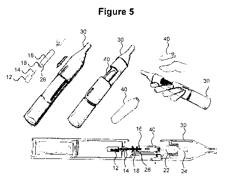
Figure 5 is a schematic illustration of an aerosol-generating system. The
aerosol-
generating system comprises a main unit 30 and a separate cartridge 40. The
main unit 30
comprises a micro stepper motor 12 with a drive shaft 14. The cartridge 40
comprises a
capsule representing the liquid storage portion. The main unit 30 further
comprises a tubing
segment 22 and a vaporiser 24 receiving liquid aerosol-forming substrate via
the tubing
segment 22 that extends from the liquid storage portion towards the
vapouriser. The vaporiser
24 is configured to heat the liquid aerosol-forming substrate directly after
the liquid aerosol-
CA 03005687 2018-05-17
WO 2017/108394 PCT/EP2016/079944
-10-
forming substrate exits the tubing segment 22.
Furthermore, the cartridge 40 comprises a lead screw 16 coupled to the drive
shaft
14 and a piston 18 that is axially moved by the lead screw 16. The liquid
storage portion
comprises a movable wall 26 that separates the liquid storage portion from the
remaining
components inside the capsule of the cartridge.
The cartridge 40 is configured to be received in a cavity within the main unit
30.
Cartridge 40 should be replaceable by a user when the aerosol-forming
substrate provided in
the cartridge 40 is depleted. When inserting a new cartridge 40, a slider at
the main unit 30
may be moved to expose the cavity. A new cartridge 40 may be inserted into the
exposed
cavity. The lead screw 16 of the cartridge 40 comprises an opening for
receiving the drive shaft
14 of the micro stepper motor 12. The capsule of the cartridge 40 comprises an
outlet for
receiving an end of the tubing segment 22.
The main unit 30 is portable and has a size comparable to a conventional cigar
or
cigarette. The main unit 30 comprises a main body and a mouthpiece portion.
The main unit
30 contains a power supply, for example a battery such as a lithium iron
phosphate battery,
electronic circuitry 10, and a cavity. Electrical connectors are provided at
the sides of the main
body to provide an electrical connection between the electric circuitry 10 and
the battery. The
mouthpiece portion comprises a plurality of air inlets and an outlet. In use,
a user sucks or
puffs on the outlet to draw air from the air inlets, through the mouthpiece
portion to the outlet,
and thereafter into the mouth or lungs of the user. Internal baffles are
provided to force the air
flowing through the mouthpiece portion past the cartridge.
The exemplary embodiments described above illustrate but are not limiting. In
view of
the above discussed exemplary embodiments, other embodiments consistent with
the above
exemplary embodiments will now be apparent to one of ordinary skill in the
art.