Note: Descriptions are shown in the official language in which they were submitted.
- 1 -
FLUID COLLECTION DEVICE AND RELATED METHODS
TECHNICAL FIELD
The present invention generally relates to articles and methods for collecting
and/or
facilitating transfer of fluids.
SUMMARY
The present invention generally relates to articles and methods for collecting
and/or
facilitating transfer of fluids, such as fluidic samples and reagents.
In one aspect, articles for introducing a fluid into a fluidic system are
provided. In
some embodiments, the article comprises a fluid collection region comprising a
substantially
vertical edge having a thickness of less than or equal to 2 mm, a sidewall,
and a bottom
portion, wherein the fluid collection region has a holding volume of less than
or equal to
about 200 microliters and a longest dimension of less than about 2 cm, and a
channel
integrally connected to and in fluidic communication with the fluid collection
region, wherein
the channel has an average cross sectional dimension of at least 0.1 mm and
less than or equal
to about 5 mm, and a length of at least about 1 mm and less than or equal to
about 10 mm.
In some embodiments, the article comprises a fluid collection region
comprising an
edge, a sidewall, and a bottom portion, and a receiving channel integrally
connected to and in
fluidic communication with the fluid collection region, wherein the receiving
channel
includes a concave portion adapted and arranged to receive a fluidic channel.
In some embodiments, the article comprises a fluid collection region
comprising a
curved edge, a sidewall, and a bottom portion, a channel integrally connected
to and in fluidic
communication with the fluid collection region, wherein the receiving channel
is adapted and
arranged to be in fluidic communication with a fluidic channel comprising a
fluid path having
a fluid path inlet and a fluid path outlet, and wherein the fluid collection
region is adapted and
arranged to hold a control fluid having a critical volume of less than or
equal to about 20
microliters without filling the fluidic channel, and to allow flow of the
control fluid into the
fluidic channel when the volume of the control fluid is at least about 25
microliters, and
Date recue/Date received 2023-05-08
- 2 -
wherein the control fluid is deionized water. In other embodiments, the
control fluid is
another control fluid described herein.
In some embodiments, the device comprises a fluidic connector comprising a
fluidic
channel that includes a fluid path having a fluid path inlet and a fluid path
outlet, wherein the
fluidic connector is adapted and arranged to connect to an inlet and/or an
outlet of a fluidic
device, and a fluid collection device for introducing a fluid into the fluidic
connector, the
fluid collection device comprising a fluid collection region comprising an
edge, a sidewall, a
bottom portion, and a receiving channel integrally connected to and in fluidic
communication
with the fluid collection region.
In another aspect, devices are provided. In some embodiments, the device
comprises
a fluidic system comprising at least one channel having an inlet and an
outlet, a fluidic
connector comprising a fluidic channel that includes a fluid path having a
fluid path inlet and
a fluid path outlet, wherein the fluidic connector is adapted and arranged to
fasten with the
fluidic system and allow fluid communication between the fluidic system and
the fluidic
.. connector, and a fluid collection device for introducing a fluid into the
fluidic connector, the
fluid collection device comprising a fluid collection region and a channel
that is adapted to
arranged to reversibly connect with the fluidic channel of the fluidic
connector.
In yet another aspect, methods are provided. in some embodiments, the method
comprises contacting a droplet of blood positioned on a surface with a fluid
collection device
comprising a fluid collection region comprising an edge and a sidewall and a
channel
integrally connected to and in fluidic communication with the fluid collection
region,
scraping the surface with the edge of the fluid collection region, and
introducing at least a
portion of the droplet into the fluid collection region.
In some embodiments, the method comprises contacting a fluid with a fluid
collection
device comprising a fluid collection region comprising an edge, a sidewall and
a bottom
portion, and a channel integrally connected to and in fluidic communication
with the fluid
collection region, wherein the fluid collection device has a holding volume of
less than or
equal to 5 mL, allowing the fluid to flow against the sidewall of the fluid
collection region by
gravity, and transferring at least a portion of the fluid from the fluid
collection device to a
fluidic channel that is reversibly connected to the fluid collection device.
Date recue/Date received 2023-05-08
- 3 -
Other advantages and novel features of the present invention will become
apparent
from the following detailed description of various non-limiting embodiments of
the invention
when considered in conjunction with the accompanying figures. In cases where
the present
specification includes conflicting and/or inconsistent disclosure, the present
specification
shall control.
BRIEF DESCRIPTION OF THE DRAWINGS
Non-limiting embodiments of the present invention will be described by way of
example with reference to the accompanying figures, which are schematic and
are not
.. intended to be drawn to scale. In the figures, each identical or nearly
identical component
illustrated is typically represented by a single numeral. For purposes of
clarity, not every
component is labeled in every figure, nor is every component of each
embodiment of the
invention shown where illustration is not necessary to allow those of ordinary
skill in the art
to understand the invention. In the figures:
FIG. IA is a schematic drawing of a fluid collection device, according to one
set of
embodiments;
FIGs. 1B-1C are cross-sectional schematic drawings of a fluid collection
device,
according to one set of embodiments;
FIGs. 1D-1G are cross-sectional schematic drawings showing a method of
collecting
a fluid sample with a fluid collection device, according to one set of
embodiments;
FIG. IH is a cross-sectional schematic drawing of a fluid collection device,
according
to one set of embodiments;
FIG. 2A is a top perspective view of a fluid collection region of a fluid
collection
device, according to one set of embodiments;
FIGs. 2B-2C are cross-sectional schematic drawings of a fluid collection
device,
according to one set of embodiments;
FIG. 3A is a schematic drawing of a fluid collection device and a fluidic
connector,
according to one set of embodiments;
FIG. 3B is a cross-sectional schematic drawing of a fluid collection device
and a
fluidic connector, according to one set of embodiments;
Date recue/Date received 2023-05-08
- 4 -
FIG. 4A is a top perspective view of a fluidic connector, according to one set
of
embodiments;
FIGs. 4B-4C are perspective view schematic drawings of a fluid collection
device and
fluidic connector, according to one set of embodiments;
FIGs. 5A-5B are perspective view schematic drawings of a fluidic connector and
a
fluidic system, according to one set of embodiments; and
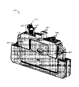
FIGs. 6A-6C are photographs of a fluid collection device, according to one set
of
embodiments.
DETAILED DESCRIPTION
Articles and methods for collecting and/or facilitating transfer of fluids are
generally
provided. In some embodiments, an article comprises a fluid collection region
for
introducing a fluid, such as a sample (e.g., blood sample) or a reagent, into
a fluidic system.
The articles and methods desciibed herein may be useful for facilitating the
filling of
relatively small channels with a fluid, such as channels of a microfluidic
device. The articles
and methods may, for example, interface with a patient sample (e.g., a droplet
of blood), or
with a macroscopic fluid source such as a pipette or syringe. In certain
embodiments, articles
and methods described herein may increase the ease of collecting a fluidic
sample from a
patient, prevent or reduce spillage of the fluidic sample, reduce
contamination of a fluidic
sample, and/or prevent or reduce air from entering a fluidic sample or device
compared to
certain existing fluid collection devices.
In some embodiments, an article for collecting and/or facilitating transfer of
fluids as
described herein is a fluid collection device. The fluid collection device may
comprise a
fluid collection region comprising an edge and a sidewall. For example, as
shown
illustratively in FIG. 1A, a fluid collection device 100 comprises a fluid
collection region 105
comprising an edge 110 and a sidewall 120. In some embodiments, edge 110 and
sidewall
120 are in direct contact with each other (although not necessarily so). In
some cases, the
edge and the sidewall may be formed from a single material (e.g., molded). In
other
embodiments, the edge and the sidewall may be formed separately and joined
together such
that they are in direct contact with each other (e.g., via an adhesive or the
like).
Date recue/Date received 2023-05-08
- 5 -
In some embodiments, at least a portion (e.g., a bottom portion) of the
sidewall is
configured and arranged to receive and/or hold a fluid. As shown
illustratively in FIG. 1B,
fluid collection device 100 (as shown as a cross-section of the fluid
collection device)
comprises fluid collection region 105. Fluid collection region 105 may
encompass edge 110
.. and sidewall 120, where sidewall 120 includes or is attached to a bottom
portion 125. In
certain embodiments, the bottom portion is configured and arranged to receive
and/or hold a
fluid such as a fluid sample or reagent (e.g., blood). At least a portion of
the edge, in some
embodiments, may be tapered, as described in more detail below. For example,
as shown in
FIG. 1B, edge 110 may comprise tapered surface 115.
In certain embodiments, the fluid collection device includes a channel. The
channel
may facilitate transfer of fluid from the fluid collection device to another
channel, device, or
fluid container (e.g., a fluidic connector, as described in more detail
below). In some
embodiments, the channel is integrally connected to and in fluidic
communication with the
fluid collection region. For example, referring again to HG. 1B, channel 130
may be
integrally connected to and in fluidic communication with fluid collection
region 105 (e.g., a
bottom or side portion of the fluid collection region).
The channel connected to the fluid collection region may have any suitable
shape
and/or configuration. In some embodiments, at least a portion of the channel
may be
concave. For example, as shown illustratively in FIG. IC, fluid collection
device 101
comprises fluid collection region 105 including edge 110, sidewall 120, and
channel 130. In
some such embodiments, channel 130 may comprise concave portion 1 32. Concave
portions
of the channel may be used, for example, for guiding the insertion of a
secondary channel,
such as a fluidic channel and/or fluidic connector, into the channel of the
fluid collection
device. In some embodiments, the fluid collection device (and/or channel
within the fluid
.. collection device) may be configured such that a secondary channel is
reversibly connected
with at least a portion of the channel of the fluid collection device (or with
the concave
portion of the channel). Irreversible connections are also possible in some
embodiments. In
embodiments in which a secondary channel is inserted into a channel of the
fluid collection
device, the channel of the fluid collection device may be considered a
receiving channel.
Date recue/Date received 2023-05-08
- 6 -
In other embodiments, a channel of a fluid collection device may include a
convex
portion, or a portion that extends outwards from the fluid collection device.
Such a channel
may, for example, be inserted into a secondary channel (e.g., a receiving
channel of a fluid
connector or device). Other configurations of channels on the fluid collection
device are also
possible.
In some embodiments, methods for collection a patient sample are provided.
Some
assays/devices require certain amounts of a patient sample (e.g., blood) to
run the test. To
obtain, for example, 12.4 microliters of blood in the device, one needs more
than 15
microliters of blood on the finger. It is difficult to hold, for example, a 15-
25 or 20-25
microliter droplet on a finger when the blood droplet is on top of the finger.
The blood is
very likely to slide off the finger in such amounts, and as a result, the
patient tends to express
as little blood as possible on the finger to avoid the droplet from sliding
off. With a small
droplet of blood, the user may scrape the blood with the end of the capillary
to obtain any
blood left on the finger to get all of the 12.4 microliters necessary for the
device. In some
instances, some of that blood might be already coagulating. During this
process, however,
any contaminants on the skin may be picked up in the sample. This process can
therefore
result in inaccurate results in some instances. For example, studies were
performed which
showed positive correlation between collection from a small blood droplet and
failure of the
test to complete normally (e.g., due to occurrence of a clog during flow of
whole blood
through the detection zones of a device).
The methods described herein may address these issues by allowing the patient
to
collect a larger and/or a less contaminated sample than otherwise would have
been possible
without such methods. For instance, in some embodiments, a device or a
component of a
device is filled (or the sample is introduced into the device) only after a
critical volume of
sample is obtained necessary for conducting an assay/use of the device. For
example, a
method may comprise introducing a certain volume of fluid (e.g., at least
about 24 microliters
or any other suitable volume described herein) into the fluid collection
region of a device
described herein, and transferring at least a portion (and in some
embodiments, not all) of the
fluid from the fluid collection device to a fluidic channel in fluid
communication with and
reversibly connected to the fluid collection device.
Date recue/Date received 2023-05-08
- 7 -
As described herein, in some embodiments, the fluid collection device may be
used
for collecting a fluid sample. During the step of collecting a fluid, at least
a portion of the
fluid collection device (e.g., at least a portion of the edge and/or tapered
edge) may contact a
surface and/or a fluid (e.g., a droplet) positioned on the surface. In certain
embodiments, the
surface comprises at least a portion of a surface of human skin of a patient
(e.g., a blood
droplet positioned on human skin, such as the skin of a finger or an ear
lobe). In some
embodiments, the surface of human skin is pierced (e.g., via a lancet, a
needle, etc.) such that
a droplet of blood is released. The edge of the fluid collection region may
contact (e.g.,
scrape) the surface of the skin such that the droplet of blood is introduced
into the interior of
the fluid collection region. In an exemplary embodiment, the surface of the
skin that has
been pierced may include a droplet of blood thereon. The droplet of blood may
be inverted
(e.g., such that the droplet of blood hangs from the surface of the skin) and
the blood can be
collected by the fluid collection device by allowing the blood to flow against
the sidewall of
the fluid collection region (e.g., by contacting the sidewall to the blood
such that the blood
flows by gravity into the fluid collection device).
In some embodiments, a method comprises performing a finger stick (e.g., to
form a
droplet of blood on a surface of the finger); holding the finger such that the
site of finger stick
points downwards (e.g., such that the droplet of blood hangs from the surface
of the skin);
and using a collection device (as described herein) to collect single droplet
of blood having a
volume of greater than or equal to 12 microliters, greater than or equal to 13
microliters,
greater than or equal to 14 microliters, greater than or equal to 15
microliters, greater than or
equal to 16 microliters, greater than or equal to 17 microliters, greater than
or equal to 18
microliters, greater than or equal to 19 microliters, greater than or equal to
20 microliters,
greater than or equal to 21 microliters, greater than or equal to 22
microliters, greater than or
equal to 23 microliters, greater than or equal to 24 microliters, greater than
or equal to 25
microliters, greater than or equal to 26 microliters, greater than or equal to
27 microliters,
greater than or equal to 28 microliters, greater than or equal to 29
microliters, or greater than
or equal to 30 microliters. In some embodiments, the volume of the droplet is
less than or
equal to 35 microliters, less than or equal to 30 microliters, less than or
equal to 25
microliters, less than or equal to 20 microliters, or less than or equal to 15
microliters.
Date recue/Date received 2023-05-08
- 8 -
Combinations of the above referenced ranges are also possible (e.g., greater
than or equal to
15 microliters and less than or equal to 35 mL). Other ranges are also
possible. In some
embodiments, instructions (e.g., written instructions) are provided to the
user to perform the
acts described above.
As one example, and as shown illustratively in FIG. 1D, edge 110 of fluid
collection
device 100 may contact a surface 140 and/or a fluid 150 (e.g., a droplet)
positioned on the
surface. In some embodiments, the edge is scraped along the surface. In some
such
embodiments, scraping the surface involves contacting the surface with the
fluid collection
device and moving the fluid collection device such that at least a portion of
a fluid present on
the surface is introduced into the fluid collection region. In some
embodiments, at least a
portion of the fluid, after contacting and/or scraping, flows along the
sidewall (e.g., interior
surface of sidewall 120 in FIG. ID) of the fluid collection device. Fluid may
flow against the
sidewall of the fluid collection region by gravity, e.g., by rotating the
fluid collection device
such that the fluid flows into a bottom portion 125 of the fluid collection
device. In some
cases, the sidewall may be coated (e.g., with a hydrophilic coating) to
facilitate fluid flow
against the sidewall. In certain embodiments, at least a portion of the fluid
contacts a
channel of the fluid collection device (e.g., channel 130 in FIG. 1D). At
least a portion of the
fluid may enter the channel (e.g., a receiving channel).
In certain embodiments, a fluid may be introduced (e.g., dispensed) into the
fluid
collection region without scraping. For example, as shown illustratively in
FIG. 1E, fluid 150
may be introduced into fluid collection region 105 of fluid collection device
100 directly.
The fluid may be introduced into the fluid collection using any suitable
method including, but
not limited to, dripping, dispensing (e.g., dispensed via a pipette, dispensed
via a syringe,
dispensed via a capillary tube), pouring, condensing, and spraying. In some
embodiments,
the fluid is introduced onto a surface of the sidewall.
In some embodiments, the fluid collection region is adapted and arranged such
that it
holds a fluid of particular volume (or range of volumes) before the fluid
beings to fill a
channel of the fluid collection device (or a fluid path inserted into the
channel, such as a
capillary tube). For instance, in some embodiments, the fluid collection
region may hold a
particular volume of fluid without the fluid filling the channel (or fluid
path, such as a fluid
Date recue/Date received 2023-05-08
- 9 -
path inlet) in fluidic communication with the fluid collection region (e.g., a
channel at the
bottom or side of the fluid collection region). In some such embodiments, the
fluid may only
enter the channel (or a fluid path within the channel) upon the fluid reaching
a volume greater
than a particular critical volume. The fluid may enter the channel (or fluid
path inserted in
the channel) by gravity and without any applied (positive or negative
pressure) applied to the
channel or fluid collection region. Advantageously, holding the fluid until a
particular
volume is present within the fluid collection region may, for example, prevent
the formation
of air bubbles in the channel (or fluid path) during collecting of the fluid.
For example,
during collection of a sample (e.g., collection of blood from a surface of
finger as a result of a
finger prick), if the sample is collected in 5 microliter increments for a
total of 30 microliters,
and assuming the critical volume required to initiate flow into the channel is
26 microliters,
the sample would not flow into the channel (or fluid path) until 30
microliters is present in
the fluid collection region. By contrast, if the geometry of the fluid
collection region did not
allow for fluid to accumulate until a critical volume had been reached before
flow was
initiated, each 5 microliter sample would fill the channel (or fluid path
inserted in the
channel) upon entering the fluid collection region. In this scenario, air
bubbles may be
present between each 5 microliter volume in the channel.
The critical volume of a particular fluid collection device, i.e., the volume
of fluid that
the fluid collection region can hold prior to filing of a channel (or a fluid
path within/inserted
in the channel) connected to the fluid collection region, may be determined by
collecting a
control fluid (e.g., deionized water, an aqueous dye solution, or a reference
material such as
total prostate specific antigen (TPSA) External Control Matrix) in the fluid
collection region
and measuring the minimum volume required for the fluid to fill a channel (or
a fluid path
within the channel) connected to and in fluidic communication with the fluid
collection
region. For example, referring to FIG. 1H, the critical volume of the fluid
collection region
may be determined by inserting a fluid path inlet 129 (e.g., a tube, such as a
capillary tube,
described in more detail below) into channel 130 (e.g., a receiving channel)
and collecting
fluid 150 (e.g., the control fluid) such that the fluid initially enters fluid
collection region 105
and contacts bottom portion 125 (e.g., without the fluid initially touching
channel 130) but
Date recue/Date received 2023-05-08
- 10 -
does not fill the fluid path inlet, and then measuring the minimum volume of
fluid 150
needed for the fluid path inlet to be filled.
In some embodiments, for purposes of determining the critical volume, the
fluid is
added in a manner such that it flows down at least a portion of the sidewall
of the fluid
collection region. Fluid path inlet 129 may be inserted in channel 130 (e.g.,
a receiving
channel) such that a terminating end of the fluid path inlet is positioned
(e.g., a maximum
height or distance 131 of the fluid path extending from the bottom portion 125
of the fluid
collection region may be) at least 50 microns, at least 100 microns, at least
150 microns, at
least 200 microns, at least 250 microns, at least 290 microns, at least 300
microns, at least
400 microns, at least 500 microns, at least 1 mm, at least 2 rnm, at least 3
mm, at least 4 mm,
at least 5 mm, at least 6 mm, at least 7 mm, at least 8 mm, or at least 9 mm
(e.g., above the
opening to channel 130 at bottom portion 125); and/or less than or equal to 10
mm, less than
or equal to 9 mm, less than or equal to 8 mm, less than or equal to 7 mm, less
than or equal to
6 mm, less than or equal to 5 mm, less than or equal to 4 mm, than or equal to
3 mm, less
than or equal to 2 mm, less than or equal to 1 mm, less than or equal to 500
microns, less than
or equal to 400 microns, less than or equal to 300 microns, less than or equal
to 290 microns,
less than or equal to 200 microns, less than or equal to 100 microns, or less
than or equal to
50 microns (e.g., above the opening to channel 130 at bottom portion 125) from
the bottom
portion of the fluid collection region. Combinations of the above-referenced
ranges are also
possible.
In some embodiments, the terminating end of the fluid path inlet may be
positioned
within the receiving channel and may not reach the bottom portion of the fluid
collection
region. For instance, the terminating end of the fluid path inlet may be
positioned within the
receiving channel at a distance from the bottom portion of the fluid
collection region (e.g., the
__ WI minating end is positioned within channel 130) that is at least 50
microns, at least 100
microns, at least 150 microns, at least 200 microns, at least 250 microns, at
least 290 microns,
at least 300 microns, at least 400 microns, at least 500 microns, at least 1
mm, at least 2 mm,
at least 3 nun, at least 4 mm, at least 5 mm, at least 6 nun, at least 7 mm,
at least 8 nun, or at
least 9 mm; and/or less than or equal to 10 mm, less than or equal to 9 mm,
less than or equal
to 8 mm, less than or equal to 7 mm, less than or equal to 6 mm, less than or
equal to 5 mm,
Date recue/Date received 2023-05-08
- 11 -
less than or equal to 4 mm, than or equal to 3 mm, less than or equal to 2 mm,
less than or
equal to 1 mm, less than or equal to 500 microns, less than or equal to 400
microns, less than
or equal to 300 microns, less than or equal to 290 microns, less than or equal
to 200 microns,
less than or equal to 100 microns, or less than or equal to 50 microns.
Combinations of the
above-referenced ranges are also possible.
In certain embodiments, the ratio of the outer cross-sectional dimension of
the fluid
path inlet and the inner cross-sectional dimension of channel 130 (e.g., the
receiving channel,
which may be measured at opening 134) of the fluid collection device is
between about
1:1.01 and about 1:1.25 or another suitable ratio as described herein. Those
skilled in the art
would understand that if the control fluid is added directly to the fluid path
inlet, the control
fluid could immediately fill the fluid path inlet, and the amount of control
fluid added would
not be considered the critical volume of the fluid collection device.
The fluid collection region may be designed to have any suitable critical
volume.
That is, the fluid collection region may be adapted and arranged to hold a
control fluid having
a particular volume without filling a channel connected to the fluid
collection region (or a
secondary channel disposed in the channel). In some embodiments, the critical
holding
volume of a control fluid may be less than or equal to 30 microliters, less
than or equal to 25
microliters, less than or equal to 22 inicroliters, less than or equal to 20
microliters, less than
or equal to 18 microliters, less than or equal to 16 microliters, less than or
equal to 14
.. microliters, less than or equal to 12 microliters, less than or equal to 10
microliters, less than
or equal to 5 microliters, less than or equal to 2 microliters, or less than
or equal to 1
microliter. In certain embodiments, a critical holding volume of control fluid
may be at least
0.1 microliters, at least 0.5 microliters, at least 1 microliter, at least 2
microliters, at least 5
microliters, at least 10 microliters, at least 12 microliters, at least 14
microliters, at least 16
.. microliters, or at least 18 microliters. Combinations of the above-
referenced ranges are also
possible (e.g., at least 0.1 microliters and less than or equal to 20
microliters). Other ranges
are also possible. In some embodiments, the control fluid (e.g., having a
volume of less than
20 microliters) may be introduced into the fluid collection region as
described herein such
that at least a portion of the control fluid contacts the channel (or a
fluidic channel disposed
therein) without filling the channel.
Date recue/Date received 2023-05-08
- 12 -
In some embodiments, the critical volume of a fluid collected using the fluid
collection device may be less than or equal to 30 microliters, less than or
equal to 25
microliters, less than or equal to 22 microliters, less than or equal to 20
microliters, less than
or equal to 18 microliters, less than or equal to 16 microliters, less than or
equal to 14
microliters, less than or equal to 12 microliters, less than or equal to 10
microliters, less than
or equal to 5 microliters, less than or equal to 2 microliters, or less than
or equal to 1
microliter. In certain embodiments, a critical holding volume of the fluid
collected using the
fluid collection device may be at least 0.1 microliters, at least 0.5
microliters, at least 1
microliter, at least 2 microliters, at least 5 microliters, at least 10
microliters, at least 12
microliters, at least 14 microliters, at least 16 microliters, or at least 18
microliters.
Combinations of the above-referenced ranges are also possible (e.g., at least
0.1 microliters
and less than or equal to 20 microliters).
In some embodiments, the control fluid is allowed to flow into and fill the
channel (or
a fluidic channel disposed therein, such a secondary channel described herein)
when the
volume of the control fluid is at least a volume greater than the critical
volume of the fluid
collection region. For example, for a fluid collection region having a
critical volume of 20
microliters, a control fluid may be introduced into the fluid collection
region such that at least
a portion of the control fluid contacts the channel and does not fill the
channel until the
volume of the control fluid introduced is greater than 20 microliters. In the
embodiments
described herein, the control fluid used for determining the critical volume
may be deionized
water, an aqueous dye solution, or an external control as described herein.
The critical
volume was also evaluated with a blood sample (a non-controlled fluid).
In some embodiments, the fluid collection region of the fluid collection
device has a
particular total volume for containing or holding a fluid, i.e., a holding
volume. The holding
volume can be determined by adding increasing increments of fluid (at a
temperature of 25
C and under 1 atm of pressure) to the fluid collection region of the fluid
collection device,
held in a substantially vertical position relative to the sidewall, before at
least a portion of the
fluid reaches the top of the sidewalls of 120 or out through the channel 130.
In such
instances, the inlet and/or outlet of any channel in fluidic communication
with the fluid
collection region is closed. As such, the holding volume does not include any
volume of
Date recue/Date received 2023-05-08
- 13 -
fluid contained in any channel of the fluid collection device. Those skilled
in the art would
understand that the holding volume may include the volume of a meniscus that
forms prior to
the spilling of water out of the fluid collection region. Without wishing to
be bound by
theory, a meniscus may form as a result of fluid surface tension at the
sidewall and/or at the
bottom of the channel.
In certain embodiments, the fluid collection region may have a holding volume
of less
than or equal to 5 mL, less than or equal to 4 mL, less than or equal to 3 mL,
less than or
equal to 2 mL, less than or equal to I mL, less than or equal to 750
microliters, less than or
equal to 500 microliters, less than or equal to 250 microliters, less than or
equal to 200
microliters, less than or equal to 100 microliters, less than or equal to 50
microliters, less than
or equal to 25 microliters, less than or equal to 12 microliters, less than or
equal to 10
microliters, or less than or equal to 5 microliters. In some embodiments, the
fluid collection
region has a holding volume of greater than or equal to 1 microliter, greater
than or equal to 5
microliters, greater than or equal to 10 microliters, greater than or equal to
12 microliters,
greater than or equal to 25 microliters, greater than or equal to 50
microliters, greater than or
equal to 100 microliters, greater than or equal to 200 microliters, greater
than or equal to 250
microliters, greater than or equal to 500 microliters, greater than or equal
to 500 microliters,
greater than or equal to 750 microliters, greater than or equal to I mL,
greater than or equal
to 2 mL, greater than or equal to 3 mL, or greater than or equal to 4 mL.
Combinations of the
above referenced ranges are also possible (e.g., greater than or equal to 1
microliter and less
than or equal to 5 mL, greater than or equal to I microliter and less than or
equal to 200
microliters, greater than or equal to 12 microliters and less than or equal to
50 microliters).
Other ranges are also possible.
The fluid collection region may have any suitable dimensions. In some
embodiments,
the fluid collection region has a longest cross-sectional dimension within a
particular range.
The longest cross-sectional dimension of the fluid collection region, as
described herein, is
measured by determining the longest linear (e.g., straight-line) distance
between two internal
points on one or more of the edge (e.g., tapered edge), the bottom portion,
and/or the sidewall
of the fluid collection region (e.g., a sidewall integrally connected to and
in fluidic
communication with the fluid collection region). For example, as shown in FIG.
IF, in some
Date recue/Date received 2023-05-08
- 14 -
embodiments, longest cross-sectional dimension 180 is measured by determining
the linear
distance between a furthermost internal point on the edge (e.g., edge 110 in
FIG. IF) from an
internal point of the sidewall (e.g., sidewall 120 in FIG. 1E) of fluid
collection device 101. In
certain embodiments, the longest cross-sectional dimension is the furthest
distance between
.. two points on the bottom and/or the edge. For example, in some embodiments,
bottom
portion 125 is curved and the longest dimension of the fluid collection region
may be
measured by determining the linear distance between the furthermost internal
point on the
edge (e.g., edge 110 in FIG. IF) and the bottom-most point of the bottom
portion (e.g.,
bottom portion 125 in FIG. 1F).
In some embodiments, the longest cross-sectional dimension of the fluid
collection
region is less than or equal to 5 cm, less than or equal to 2 cm, less than or
equal to 1.5 cm,
less than or equal to 1 cm, less than or equal to 0.5 cm, less than or equal
to 0.2 cm, or less
than or equal to 0.1 cm. In certain embodiments, the longest cross-sectional
dimension of the
fluid collection region is greater than or equal to 0.05 cm, greater than or
equal to 0.1 cm,
greater than or equal to 0.2 cm, greater than or equal to 0.5 cm, greater than
or equal to 1 cm,
or greater than or equal to 1.5 cm. Combinations of the above-referenced
ranges are also
possible (e.g., greater than or equal to 0.05 cm and less than or equal to 2
cm). As described
herein, the fluid collection region may include an edge, i.e., an outermost
portion of the fluid
collection region. The edge may facilitate collection of a fluid, such as when
the edge is
scraped against a surface on which a droplet of fluid is positioned.
In some embodiments, the edge may have a particular shape. In certain
embodiments,
the edge may be rounded or curved. For example, as shown illustratively in
FIGs. 2A-2C, a
fluid collection device 200 comprises a fluid collection region 202. Fluid
collection region
202 may comprise an edge 210, a sidewall 220, a bottom portion 225, and a
channel 230. In
some such embodiments, edge 210 may be curved and may have a particular radius
of
curvature. In certain embodiments, the radius of curvature of the edge may be
greater than or
equal to 1 mm, greater than or equal to 2 mm, greater than or equal to 3 mm, 5
mm, greater
than or equal to 6 mm, greater than or equal to 7 inm, greater than or equal
to 8 mm, or
greater than or equal to 9 mm. In some embodiments, the radius of curvature of
the edge is
less than or equal to 10 mm, less than or equal to 9 mm, less than or equal to
8 mm, less than
Date recue/Date received 2023-05-08
- 15 -
or equal to 7 mm, less than or equal to 6 mm, less than or equal to 5 mm, less
than or equal to
3 mm, or less than or equal to 2 mm. Combinations of the above referenced
ranges are also
possible (e.g., greater than or equal to I mm and less than or equal to 10 mm,
greater than or
equal to 5 mm and less than or equal to 10 mm). Other ranges are also
possible. In certain
embodiments, the edge is substantially linear in shape. Other edge geometries
and shapes are
also possible, including but not limited to V-shaped, U-shaped, rectangular,
polygonal with n
sides (e.g., with a large n, the polygonal shape may approximate a circular
shape), elliptical,
and compound curves. The edge may have a shape substantially similar to the
shape of the
sidewall.
In some embodiments, at least a portion of the edge is oriented within 45
degrees,
within 40 degrees, within 35 degrees, within 30 degrees, within 25 degrees,
within 20
degrees, within 15 degrees, within 10 degrees, within 5 degrees, within 2
degrees, or within I
degree of vertical (relative to the orientation of a channel of the fluid
collection device).
Other angles are also possible. For example, as illustrated in FIG. 1G, fluid
collection device
.. 102 comprises edge 112 and a portion of the sidewall oriented within 45
degrees of vertical.
In some embodiments, all or a portion of the edge is substantially vertical.
In certain
embodiments, all or a portion of the edge is within at least one of the angles
noted above,
relative to the orientation of a channel of the fluid collection device. For
example, referring
again to FIGs. 2A-2C, in some embodiments, fluid collection device 200
comprises edge 210
which is substantially vertical.
In certain embodiments, the edge is tapered. A tapering edge may facilitate
the
transfer of a fluid from a surface to the fluid collection region. In some
cases, the tapered
edge may reduce or prevent the presence of air bubbles in the collected fluid
and/or prevent
contamination of the collected fluid. As shown in FIG. 1B, tapered surface 115
may be
located on an inner side relative to the fluid collection region. However, the
tapered surface
may be located on an outer side relative to the fluid collection region. In
certain
embodiments, both an inner side and an outer side of edge 110 may be tapered.
Referring
again to FIGs. 2A-2C, fluid collection region 202 may comprise a tapered edge
215 in direct
contact with edge 210. In some embodiments, the tapered edge may have any
suitable taper
.. angle, as measured versus the orientation of a channel of the fluid
collection device. In
Date recue/Date received 2023-05-08
- 16 -
certain embodiments, the taper angle of the tapered edge is at least 0
degrees, at least 1
degree, at least 5 degrees, at least 10 degrees, at least 20 degrees, at least
30 degrees, at least
45 degrees, at least 60 degrees, at least 70 degrees, or at least 80 degrees.
In some
embodiments, the taper angle of the tapered edge may be less than or equal to
90 degrees,
less than or equal to 80 degrees, less than or equal to 70 degrees, less than
or equal to 60
degrees, less than or equal to 45 degrees, less than or equal to 30 degrees,
less than or equal
to 20 degrees, less than or equal to 10 degrees, less than or equal to 5
degrees, or less than or
equal to 1 degree. Combinations of the above-referenced ranges are also
possible (e.g., at
least 1 degree and less than or equal to 90 degrees). Other ranges are also
possible.
The edge of the fluid collection region may have any suitable maximum
thickness.
For example, in some embodiments, the maximum thickness of the edge is less
than 2 mm,
less than 1.5 mm, less than 1 mm, less than 0.5 mm, less than 0.25 mm, or less
than or equal
to 0.1 mm. In certain embodiments, the maximum thickness of the edge is
greater than or
equal to 0.05 mm, greater than or equal to 0.1 mm, greater than or equal to
0.25 mm, greater
than or equal to 0.5 mm, greater than or equal to 1 mm, or greater than or
equal to 1.5 mm.
Combinations of the above-referenced ranges are possible (e.g., greater than
or equal to 0.1
mm and less than 2 mm). Other ranges are also possible. In some embodiments,
the edge may
not have a uniform thickness.
As described herein, a fluid collection region may include a sidewall. The
sidewall
may facilitate the holding of a volume of fluid to be collected. In some
embodiments, the
sidewall may include one or more channels (e.g., for transferring a fluid) as
described herein.
The sidewall may, in some cases, allow for the collection of a particular
volume of a fluid in
the fluid collection region without filling the one or more channels until a
minimum holding
volume is exceeded within the fluid collection region, as described above.
Advantageously,
the sidewall may, in some embodiments, prevent spillage and/or contamination
of a fluid to
be collected prior to transfer of the fluid to a fluidic connector and/or
fluidic system.
The sidewall may have any suitable shape. For example, in certain embodiments,
the
sidewall may have at least one cross-section, measured relative to vertical,
which has a shape
such as a square, rectangle, polygon, ellipse, circle, or triangle. For
example, referring again
Date recue/Date received 2023-05-08
- 17 -
to FIGs. 2A-2C, sidewall 220 comprises at least one cross-section, measured
relative to
vertical, which has a circular shape. Other shapes are also possible.
The sidewall of the fluid collection region may have any suitable maximum
thickness.
For example, in some embodiments, the maximum thickness of the sidewall is
less than 5
mm, less than 3 mm, less than 2 mm, less than 1.5 mm, less than 1 mm, less
than 0.5 mm, or
less than 0.25 mm. In certain embodiments, the maximum thickness of the
sidewall is
greater than or equal to 0.1 mm, greater than or equal to 0.25 mm, greater
than or equal to 0.5
mm, greater than or equal to 1 mm, or greater than or equal to 1.5 mm.
Combinations of the
above-referenced ranges are possible (e.g., greater than or equal to 0.1 mm
and less than 2
mm). Other ranges are also possible. In some embodiments, the sidewall may
have a varying
thickness (e.g., across a length, width, or circumference of the sidewall).
In some embodiments, the sidewall (or fluid collection region formed by the
sidewalls) has a particular largest cross-sectional dimension. The largest
cross-sectional
dimension may be a linear dimension measured from one portion of the sidewall
to an
opposing portion of the sidewall, e.g., dimension 231 shown in FIG. 2A. In
some
embodiments, the largest cross-sectional dimension may be a width or diameter
of the fluid
collection region fonned by the sidewalls. In some embodiments, the largest
cross-sectional
dimension of the sidewall (or fluid collection region formed by the sidewalls)
is less than or
equal to 2 cm, less than or equal to 1.5 cm, less than or equal to 1 cm, less
than or equal to 0.5
cm, less than or equal to 0.2 cm, less than or equal to 0.1 cm, less than or
equal to 0.05 cm, or
less than or equal to 0.02 cm. In certain embodiments, the largest cross-
sectional dimension
of the sidewall (or fluid collection region formed by the sidewalls) is
greater than or equal to
0.01 cm, greater than or equal to 0.02 cm, greater than or equal to 0.05 cm,
greater than or
equal to 0.1 cm, greater than or equal to 0.2 cm, greater than or equal to 0.5
cm, greater than
or equal to 1 cm, or greater than or equal to 1.5 cm. Combinations of the
above-referenced
ranges are also possible (e.g., greater than or equal to 0.01 cm and less than
or equal to 2 cm).
As described herein, in some embodiments, the fluid collection device
comprises a
bottom portion. The bottom portion may have any suitable shape for receiving a
fluid. In
some embodiments, the bottom portion has a concave shape. For example, as
shown in FIGs.
2A-2C, bottom portion 225 is concave and rounded. In some embodiments, the
shape of the
Date recue/Date received 2023-05-08
- 18 -
bottom portion may be rounded, square, beveled, or funnel-like (e.g., at least
partially
conical). Other shapes are also possible. The bottom portion may include one
or more
channels (e.g., for transferring a fluid) as described herein.
As described herein, the fluid collection device may include one or more
channels
(e.g., microfluidic channels) connected thereto. In some embodiments, the
channel is
integrally connected to and in fluidic communication with the fluid collection
region. The
channels may, for example, facilitate transfer of fluid from the fluid
collection device to a
secondary channel or device. In certain embodiments, a channel described
herein is a
receiving channel that can receive a secondary channel for fluid transfer.
In some embodiments, referring again to FIG. 1H, fluid collection region 105
may be
designed to have a critical volume greater than the volume of fluid path inlet
129 (or the fluid
path itself). For example, fluid collection region 105 may be configured and
arranged such
that multiple fluid path inlets may be inserted and removed (e.g.,
sequentially) such that at
least a portion of the fluid 150 may be transferred from the fluid collection
region to more
than one (e.g., two or more, three or more, four or more, five or more) fluid
path inlets. In an
exemplary embodiment, a fluid is introduced to fluid collection region 105
and, upon
reaching a sufficient volume of fluid (e.g., a volume greater than the
critical volume of fluid
collection region 105), at least a portion of the fluid flows into a first
fluid path inlet (e.g., a
first fluid path inlet inserted into channel 130). The first fluid path inlet
may be removed
from the receiving channel (e.g., after filling of the first fluid path inlet
with at least a portion
of the fluid) and, in some embodiments, a second fluid path inlet may be
inserted into the
receiving channel such at least a portion of the fluid (e.g., fluid 150)
remaining in fluid
collection region 105 is transferred to the second fluid path inlet. In some
embodiments,
channel 130 and/or fluid collection region 105 are configured and arranged
such that, after
removal of the first fluid path inlet, fluid 150 does not substantially leak
from the fluid
collection region and/or into the receiving channel (e.g., the fluid does not
leak into channel
130 in the absence of a fluid path inlet present within the channel). The
first and second fluid
path inlets may be used to introduce the fluid into a fluidic device described
herein (e.g., a
microfluidic device), or multiple fluidic devices.
Date recue/Date received 2023-05-08
- 19 -
In some embodiments, a channel of the fluid collection device (e.g., in
fluidic
communication with the fluid collection region) has a particular length. In
certain
embodiments, the length of the channel includes any shaped portions such as
concave
portions (e.g., concave portion 232 in FIGs. 2B-2C). In some embodiments, the
length of the
channel is greater than or equal to 1 mm, greater than or equal to 2 mm,
greater than or equal
to 3 mm, greater than or equal to 5 mm, greater than or equal to 7 mm, or
greater than or
equal to 9 mm. In certain embodiments, the length of the channel is less than
or equal to 10
mm, less than or equal to 9 mm, less than or equal to 7 mm, less than or equal
to 5 mm, less
than or equal to 3 mm, or less than or equal to 2 mm. Combinations of the
above-referenced
ranges are also possible (e.g., greater than or equal to 1 mm and less than or
equal to 10 ram).
Other ranges are also possible. In embodiments in which more than one channel
is associated
with the fluid collection device, each channel may independently have a length
in one or
more of the above-referenced ranges.
A channel of the fluid collection device (e.g., a channel integrally connected
to and/or
in fluidic communication with the fluid collection region) may have any
suitable average
inner cross-sectional dimension. The inner cross-sectional dimension (e.g., an
inner
diameter) of the channel is measured perpendicular to the direction of fluid
flow. In some
embodiments, the average inner cross-sectional dimension of the channel is
less than or equal
to 5 mm, less than or equal to 4 mm, less than or equal to 3 mm, less than or
equal to 2 mm,
less than or equal to 1 mm, less than or equal to 0.5 mm, less than or equal
to 0.3 mm, or less
than or equal to 0.2 mm. In certain embodiments, the average inner cross-
sectional
dimension of the channel is at least 0.1 mm, at least 0.2 mm, at least 0.3 mm,
at least 0.5 mm,
at least 1 mm, at least 2 mm, at least 3 mm, or at least 4 mm. Combinations of
the above-
referenced ranges are also possible (e.g., at least 0.1 mm and less than or
equal to 5 mm).
Other ranges are also possible. In embodiments in which more than one channel
is associated
with the fluid collection device, each channel may independently have an
average inner
cross-sectional dimension in one or more of the above-referenced ranges.
As described herein, in some embodiments, a channel of the fluid collection
device
(e.g., a receiving channel) includes a concave portion. For example, referring
again to FIG.
1C, channel 130 comprises a concave portion 132. In some embodiments, at least
a portion
Date recue/Date received 2023-05-08
- 20 -
of the channel (e.g., receiving channel) is configured and arranged to
receiving a secondary
channel, such as a fluidic channel of a fluidic connector or other fluidic
device. The concave
portion may, in some cases, assist in the alignment and/or receiving of the
secondary channel,
such as the fluidic channel of a fluidic connector. For example, in certain
embodiments, at
least a portion of a surface of a fluidic channel of a fluidic connector may
be contacted with a
surface of the concave portion such that the concave portion guides the
fluidic channel into
the channel of the fluid collection device. The concave portion may have any
suitable cross-
sectional shape (e.g., rounded, square, beveled, conical).
In some embodiments, the bottom portion of the sidewall (e.g., bottom portion
125 of
.. sidewall 120 in FIG. 1C) comprises a first opening 134 that is fluidically
connected to
channel 130 and the channel has a second opening 136 having a diameter greater
than the
diameter of the first opening. In certain embodiments, the diameter of the
first opening and
the diameter of the second opening are equal; however, other ratios are also
possible. For
example, in some embodiments, the ratio of the diameter of the second opening
to the first
.. opening is greater than or equal to 1, greater than or equal to 1.25,
greater than or equal to
1.5, greater than or equal to 1.75, greater than or equal to 2, greater than
or equal to 2.5,
greater than or equal to 3, greater than or equal to 4, or greater than or
equal to 5. In certain
embodiments, the ratio of the diameter of the second opening to the first
opening is less than
or equal to 10, less than or equal to 5, less than or equal to 4, less than or
equal to 3, less than
.. or equal to 2.5, less than or equal to 2, less than or equal to 1.75, less
than or equal to 1.5, or
less than or equal to 1.25. Combinations of the above-referenced ranges are
also possible
(e.g., greater than or equal to 1 and less than or equal to 10). Other ranges
are also possible.
In some embodiments, the second opening (e.g., comprising a portion of the
concave portion)
is configured and arranged to receive a secondary channel such as a fluidic
channel of a
fluidic connector.
The fluid collection device or any portion of the fluid collection device
(e.g., the fluid
collecting region, the edge, the tapered edge, the sidewall, the bottom
portion) may be made
from any suitable material. Non-limiting examples of suitable materials
include
polycarbonate, copolymers of styrene and butadiene, polyethylene (e.g., low
density
polyethylene, high density polyethylene), polypropylene, polyvinyl chloride,
polystyrene,
Date recue/Date received 2023-05-08
- 21 -
polytetrafluoroethylene, polyurethane, poly(methyl methacrylate),
acrylonitrile butadiene
styrene, polylactic acid, poly ether ketone, polyetherimide, polyphenylene
oxide, and
polyethylene terephthalate. Other materials are also possible. In some cases,
the material
may be biocompatible. In certain embodiments, the material may comprise one or
more
additives. In some embodiments, the additive may change the surface energy of
the material
(e.g., such that the material is hydrophobic, such that the material is
hydrophilic) relative to
the surface energy of the material without the additive. The additive may be
present in any
suitable amount (e.g., between 0.1 wt% and 20 wt% of the combined weight of
the material).
In some embodiments, a portion of the fluid collection device (e.g., at least
a portion
of the edge (e.g., tapered edge), the sidewall, the bottom portion, and/or the
receiving
channel) may comprise a treated surface. For instance, all or portions of a
surface may be
treated to modify a physical and/or chemical property of the surface. In some
embodiments,
at least a portion of the fluid collection device is coated with a chemical or
biological reagent
(e.g., a small molecule or a biomolecule). Non-limiting examples of suitable
small molecules
include anticoagulants (e.g., EDTA, citrate), detergents (e.g., sodium dodecyl
sulfate, sodium
decyl sulfate, TweenTm-20, TweenTm-40, TweenTm-80, fluorinated detergents such
as
Capstone FS-50 and FS-51, perfluorohexanoic acid, perfluorooctanoic acid),
solubilization
agents (e.g., beta-cyclodextrin, beta-cyclodextrin derivatized with functional
groups such as
methyl-, hydroxyethyl-, and hydroxypropyl- ), and pH buffers (e.g., acetate,
citrate, ACES,
borate, tetraborate, carbonate buffers). Non-limiting examples of suitable
biomolecules
include (anti-) coagulant (e.g., heparin, coagulations factor) and , proteins
(e.g., mouse IgG,
antibodies, protein conjugates, bovine serum albumin). In some embodiments, at
least a
portion of the fluid collection device is coated such that the portion of the
fluid collection
device is hydrophilic or hydrophobic. Those skilled in the art would be
capable of selecting
suitable methods for making a surface hydrophilic or hydrophobic including,
but not limited
to, chemical functionalization. In some embodiments, at least a portion of the
fluid collection
device is treated with corona/plasma treatment and/or coated with a particular
molecule or
functionality (e.g., amine, carboxylic acid, silane).
At least a portion of the fluid collection device (e.g., at least a portion of
the edge, the
tapered edge, the sidewall, the bottom portion, and/or the receiving channel)
may have a
Date recue/Date received 2023-05-08
- 22 -
particular root mean square (RMS) surface roughness. In certain embodiments,
the RMS
surface roughness may be, for example, less than or equal to about 5 microns,
less than or
equal to about 3 microns, less than or equal to about 1 micron, less than or
equal to about 0.8
microns, less than or equal to about 0.5 microns, less than or equal to about
0.3 microns, less
than or equal to about 0.1 microns, less than or equal to about 0.08 microns,
less than or equal
to about 0.05 microns, less than or equal to about 0.08 microns, less than or
equal to about
0.01 microns, or less than or equal to about 0.005 microns. In some instances,
the RMS
surface roughness may be greater than or equal to about 0.005 microns, greater
than or equal
to about 0.01 microns, greater than or equal to about 0.05 microns, greater
than or equal to
about 0.1 microns, greater than or equal to about 0.5 microns, greater than or
equal to about 1
micron, or greater than or equal to about 3 microns. Combinations of the above-
referenced
ranges are also possible (e.g., greater than or equal to about 0.05 microns
and less than or
equal to about 5 microns, greater than or equal to about 0.05 microns and less
than or equal to
about 1 micron). In some embodiments, surfaces that contact are configured to
contact a
fluid (e.g., a surface of the fluid collection region) may have a surface
roughness ranging
between about 0.05 and 0.1 microns. RMS surface roughness is a term known to
those skilled
in the art, and may be expressed as:
-1/2
1/2 I
= [((Z Z,õ = (Z¨z,)2dA
_A A
where A is the surface to be examined, and lz ¨ zml is the local height
deviation from the
mean. RMS surface roughness, as described herein, may be determined using
profilometry.
In general, the roughness of a surface may be formed during fabrication or
later
modified using any suitable method. Exemplary methods of fabricating or
modifying the
surface roughness include chemical etching (e.g., acid, alkaline, corrosive
solvent), plasma
etching (e.g., low pressure, atmospheric, flame, plasma etching with inert
and/or reactive
gases), electrochemical etching, corona discharge, mechanical methods (e.g.,
mechanical
machining, laser machining, mechanical polishing, mechanical grinding, bead-
blasting, grit-
blasting, shot-peening), ultrasonic machining, electrical methods (e.g.,
electrochemical
polishing, electric discharge machining, electroforming ), coating (e.g., by
spray-coating,
physical vapor deposition, chemical vapor deposition, painting), and
combinations thereof.
Date recue/Date received 2023-05-08
- 23 -
In some instances, the surface roughness may be produced using a molding
process. The
surface roughness of the mold may be modified using any of the above methods
and/or
coating or plating the mold surface. Other methods of producing a desired
surface roughness
are also possible.
In some embodiments, at least a portion of the fluid collection device may
have a
particular wettability (e.g., of at least about 20 dynes/cm and less than or
equal to about 60
dynes/cm). In some embodiments, at least a portion of the fluid collection
device has a
wettability of at least 20 dynes/cm, at least 25 dynes/cm, at least 30
dynes/cm, at least 35
dynes/cm, at least 40 dynes/cm, at least 42 dynes/cm, at least 45 dynes/cm, at
least 50
dynes/cm, at least 55 dynes/cm, or at least 56 dynes/cm. In certain
embodiments, at least a
portion of the fluid collection device has a wettability of less than or equal
to 60 dynes/cm,
less than or equal to 56 dynes/cm, less than or equal to 55 dynes/cm, less
than or equal to 50
dynes/cm, less than or equal to 45 dynes/cm, less than or equal to 42
dynes/cm, less than or
equal to 40 dynes/cm, less than or equal to 35 dynes/cm, less than or equal to
30 dynes/cm, or
less than or equal to 25 dynes/cm. Combinations of the above-referenced ranges
are also
possible (e.g., at least 20 dynes/cm and less than or equal to 60 dynes/cm, at
least 35
dynes/cm and less than or equal to 42 dynes/cm, at least 20 dynes/cm and less
than or equal
to 56 dynes/cm). Other ranges are also possible. Wettability, as described
herein, may be
determined by contact angle goniometry.
As described herein, in some embodiments, a fluid collection device comprising
a
fluid collection region can facilitate introduction of a fluid into a
secondary vessel for
containing at least a portion of the fluid, such as a device, adapter,
channel, container, or
fluidic connector. For example, referring FIG. 3A, a system 300 comprises a
fluid collection
device comprising an edge 310 and a sidewall 320. The fluid collection device
may facilitate
the transfer of a fluid into a vessel 360. In some embodiments, the vessel is
a container such
as a vial. The vessel may be contacted with or be connected with the fluid
collection device
(e.g., at a receiving channel of the fluid collection device). Such contact
may be reversible or
irreversible.
In some embodiments, the vessel is a fluidic connector (i.e., a fluidic device
that
comprises a fluidic channel). In some embodiments, the fluidic connector may
serve as an
Date recue/Date received 2023-05-08
- 24 -
adapter for a fluidic system, as described in more detail herein. In certain
embodiments, the
fluidic connector includes a fluid path having a fluid path inlet and a fluid
path outlet. In
some such embodiments, the fluidic channel (or fluid path) is adapted and
arranged to
connect to the fluid collection device (e.g., at the receiving channel).
Referring now to FIG.
3B, in some embodiments, a system 300 comprises a fluid collection device
comprising an
edge 310 (with an edge surface 315, optionally tapered), a sidewall 320, a
bottom portion
325, and a receiving channel 330. In some such embodiments, system 300 further
comprises
a fluidic connector 360 (e.g., a secondary fluidic device) comprising a
fluidic channel 365. In
certain embodiments, the receiving channel (receiving channel 330) of the
fluid collective
device is configured to receive the fluidic channel (fluidic channel 365) of
the fluidic
connector. For instance, the fluidic channel of the fluidic connector may be a
tube or channel
that extends from the fluidic connector. In some such embodiments, the fluidic
channel of
the fluidic connector may be at least partially disposed within, and in
fluidic connection with,
the receiving channel of the fluid collection device. In some embodiments,
upon connection
of the fluid collection device and the fluidic connector, the fluidic channel
of the fluidic
connector extends beyond the bottom portion (e.g., bottom portion 325) of the
fluid collection
device. For example, the fluidic channel of the fluidic connect may traverse
the entire length
of the receiving channel, and extend beyond the receiving channel and the
bottom portion of
the fluid collection device, such that it protrudes upwards into the fluid
collection region. In
certain embodiments, the fluidic channel may be reversibly attached to the
receiving channel.
In some embodiments, a fluid (e.g., sample or reagent) introduced into the
fluid
collection device may be transferred (e.g., upon reaching a certain volume as
described
above) into the receiving channel and/or the fluidic channel disposed within
the receiving
channel.
The fluidic channel of a fluidic connector may comprise a fluid path inlet and
a fluid
path outlet. For example, as shown illustratively in FIG. 4A, a fluidic
connector 460
comprises fluidic channel 465 having a fluid path inlet 475 and fluid path
outlet 480. In
certain embodiments, the fluid path inlet connects to the receiving channel of
the fluid
collection device. In some such embodiments, upon connection of the fluid
collection device
and the fluidic connector, the fluid path inlet of the fluidic connector
connects to the
Date recue/Date received 2023-05-08
- 25 -
receiving channel of the fluid collection device to allow fluid communication
between the
fluidic connector and the fluid collection device. In some embodiments, upon
connection of
the fluid collection device and the fluidic connector, the fluid path inlet of
the fluidic
connector extends beyond the bottom portion of the fluid collection device.
For example, the
fluidic channel of the fluidic connect may traverse the entire length of the
receiving channel,
and extend beyond the receiving channel and the bottom portion of the fluid
collection
device, such that it protrudes upwards into the fluid collection region. In
certain
embodiments, the fluidic channel is a capillary tube.
Fluidic connectors and components thereof are described in more detail, for
example,
in U.S. Patent No. 8,202,492, issued June 19, 2012 (filed May 1, 2008) and
entitled "Fluidic
Connectors and Microfluidic Systems".
The fluidic channel of a fluidic connector may have any suitable average inner
cross-
sectional dimension (e.g., average inner diameter of the fluid path). in some
embodiments,
the average inner cross-sectional dimension of the fluidic channel is less
than or equal to
5mm, less than or equal to 4 mm, less than or equal to 3 mm, less than or
equal to 2 mm, less
than or equal to 1 mm, less than or equal to 0.5 mm, less than or equal to 0.3
mm, or less than
or equal to 0.2 mm. In certain embodiments, the average inner cross-sectional
dimension of
the fluidic channel is at least 0.1 mm, at least 0.2 mm, at least 0.3 mm, or
at least 0.5 mm, at
least 1 mm, at least 2 mm, at least 3 mm, or at least 4 mm. Combinations of
the above-
referenced ranges are also possible (e.g., at least 0.1 mm and less than or
equal to 5 mm).
Other ranges are also possible.
In some embodiments, the ratio of the average inner cross-sectional dimension
of the
fluidic channel and the average inner cross-sectional dimension of the
receiving channel is
less than 100, less than 50, less than 25, less than 20, less than 10, less
than 5, less than 4, less
than 2, less than 1.5, or less than 1.2. In certain embodiments, the ratio of
the average inner
cross-sectional dimension of the fluidic channel and the average inner cross-
sectional
dimension of the receiving channel is greater than or equal to 1.1, greater
than or equal to
1.2, greater than or equal to 1.5, greater than or equal to 2, greater than or
equal to 4, greater
than or equal to 5, greater than or equal to 10, greater than or equal to 20,
greater than or
equal to 25, or greater than or equal to 50. Combinations of the above-
referenced ranges are
Date recue/Date received 2023-05-08
- 26 -
also possible (e.g., greater than or equal to 1.1 and less than 100, greater
than or equal to 1.1
and less than 25). Other ranges are also possible.
In certain embodiments, the ratio of the outer cross-sectional dimension of
the fluid
path inlet of the fluidic connector and the inner cross-sectional dimension of
the receiving
channel (e.g., measured at opening 134 shown in FIG. IC) of the fluid
collection device is
between about 1:1.01 and about 1:1.25 For example, referring again to FIG. 3B,
the ratio of
the inner cross-sectional dimension of receiving channel 330 and the outer
cross-sectional
dimension of fluidic channel 365 (measured at fluid path inlet 367 of fluidic
channel 365)
may be between about 1:1.01 and about 1:1.25. In some embodiments, the ratio
of the outer
cross-sectional dimension of the fluid path inlet and the inner cross-
sectional dimension of
the receiving channel is less than or equal to about 1:1.01, less than or
equal to about 1:1.02,
less than or equal to about 1:1.05, less than or equal to about 1:1.07, less
than or equal to
about 1:1.09, less than or equal to 1:1.1, less than or equal to 1:1.25, or
less than or equal to
about 1:1.5. In certain embodiments, the ratio of the outer cross-sectional
dimension of the
fluid path inlet and the inner cross-sectional dimension of the receiving
channel is at least
about 1:1.5, at least about 1:1.25, at least about 1:1.1, at least about
1:1.09, at least about
1:1.07, at least about 1:1.05, or at least about 1:1.02. Combinations of the
above-referenced
ranges are also possible (e.g., at least about 1:1.1 and less than or equal to
about 1:1.01).
Other ranges are also possible.
A fluidic channel of the fluidic connector (or of a vessel) may have any
suitable
volume. In certain embodiments, the volume of the fluidic channel is less than
or equal to 50
microliters, less than or equal to 40 microliters, less than or equal to 30
microliters, less than
or equal to 20 microliters, less than or equal to 18 microliters, less than or
equal to 16
microliters, less than or equal to 14 microliters, less than or equal to 12
microliters, less than
or equal to 10 microliters, less than or equal to 5 microliters, less than or
equal to 2
microliters, or less than or equal to 1 microliter. In certain embodiments,
the volume of the
fluidic channel is at least 0.1 microliters, at least 0.5 microliters, at
least 1 microliter, at least
2 microliters, at least 5 microliters, at least 10 microliters, at least 12
microliters, at least 14
microliters, at least 16 microliters, at least 18 microliters, at least 20
microliters, at least 30
.. microliters, or at least 40 microliters. Combinations of the above-
referenced ranges are also
Date recue/Date received 2023-05-08
- 27 -
possible (e.g., at least 0.1 microliters and less than or equal to 20
microliters). Other ranges
are also possible.
In some embodiments, the fluid collection device may comprise one or more
additional components (e.g., fluidic features, non-fluidic features) which
form one or more
additional connections or attachment points between the fluid collection
device and the vessel
to which the fluid collection device connects (e.g., fluidic connector). In
certain
embodiments, the fluid collection device comprises at least one fluidic
feature
complementary to the fluid path outlet of the fluidic connector so as to form
a fluidic
connection between the fluid path outlet and the fluid collection device upon
connection.
In some embodiments, the fluid collection device comprises a region configured
to
receive at least a second portion of the fluidic channel (e.g., the fluid path
outlet) of a vessel
to which the fluid collection device connects (e.g., fluidic connector).
Referring again to
FIGs. 4B-4C, fluid collection device 401 comprises region 440 configured to
receive at least
a second portion of the fluidic channel (e.g., such as fluid path outlet 480
of fluidic channel
465 of fluidic connector 460, shown in FIG. 4A). Region 440 may have any
suitable shape
and may be configured, in some embodiments, to cover (e.g., cap) the second
portion of the
fluidic channel. In some such embodiments, region 440 may protect the second
portion of
the fluidic channel from, for example, contamination. In other embodiments,
the region
comprises an opening.
In certain embodiments, the fluid collection device comprises at least one non-
fluidic
feature complementary to a non-fluidic feature of the vessel to which the
fluid collection
device connects (e.g., fluidic connector). In some such embodiments, the non-
fluid feature of
the fluid collection device and the complementary non-fluidic feature of the
vessel (e.g.,
fluidic connector) may form a non-fluidic connection between the fluidic
connector and the
vessel upon connection. In some cases, the non-fluidic feature(s) of the fluid
collection
device and/or of the vessel (e.g., fluidic connector) may guide insertion of
the fluid collection
device into the vessel during use. Additionally or alternatively, the non-
fluidic feature(s) of
the fluid collection device may facilitate attachment of the fluid collection
device to the
vessel during transfer of fluid from the fluid collection device to the
fluidic connector.
Date recue/Date received 2023-05-08
- 28 -
Referring now to FIGs. 4B-4C, a fluid collection device 401 comprises non-
fluidic
features 455 which have a shape and configuration that are complementary to
the shape and
configuration of non-fluidic features on fluidic connector 460. For example,
as shown
illustratively in FIG. 4C, fluidic connector 460 comprises rails 462 which are
shaped and
dimensioned to be complementary to the shape and dimension of features 455 on
the fluid
collection device. In some embodiments, the rail is a raised feature. In
certain embodiments,
the rail is an embedded feature. The rail may have any suitable shape and may
be, in some
cases, elongated, rounded, or square. Other shapes and configurations are also
possible.
Although FIGs. 4B-4C show non-fluidic features positioned at particular
locations, in
other embodiments, the features can be located any suitable location on the
fluidic connector
and/or the fluid collection device. Furthermore, although FIGs. 4B-4C show non-
fluidic
features in the form of two components (e.g., rails 462), in some embodiments
non-fluidic
features may be in the form of a single component. In other embodiments, the
non-fluidic
features are in the form of more than two components.
In some embodiments, the fluid collection device and/or the fluidic connector
comprises an attachment mechanism. In certain embodiments, the attachment
mechanism
comprises an opening configured to receive the fluidic connector. Referring
again to FIG.
2C, in some embodiments, fluid collection device 200 comprises attachment
mechanism 250.
In certain embodiments, the attachment mechanism may connect to a
complementary feature
on the fluidic connector. For example, referring to FIG. 4C, fluid collection
device
401comprises attachment mechanism 450 and fluidic connector 460 comprises
complementary attachment mechanism 452. Non-limiting examples of suitable
attachment
mechanisms include clips (and receiving portions), magnets, friction fit, or
the like. Other
attachment mechanisms are also possible. In certain embodiments, fluid
collection device
comprises an attachment mechanism comprising a hinge. The attachment mechanism
may
facilitate attachment of the fluid collection device to the vessel (e.g.,
fluidic connector) during
transfer of fluid from the fluid collection device to the vessel. The
attachment mechanism
may be reversible to allow reversible attachment between the fluid collection
device and the
vessel, or irreversible to allow irreversible attachment between the fluid
collection device and
the vessel.
Date recue/Date received 2023-05-08
- 29 -
As described herein, in some embodiments, once fluid is collected using a
fluid
collection device, at least a portion of the fluid may be transferred to a
vessel (e.g., fluidic
connector). In some embodiments, at least a portion of the collected fluid is
transferred to a
fluidic connector, which can be connected to, and/or is part of, an analysis
device. At least a
portion of the fluid from the fluidic connector can then be transferred to the
analysis device.
In other embodiments, at least a portion of the collected fluid is transferred
to an analysis
device directly (e.g., a fluidic connector may be part of the analysis device
directly).
An analysis device to which the vessel (fluidic connector) or fluid connection
device
may connect may comprise a fluidic system. In some embodiments, the fluidic
system
comprises at least one channel having an inlet and an outlet. In certain
embodiments, a
fluidic connector that contains a fluid (e.g., a sample or reagent), such as a
fluid transferred to
the fluidic connector by the fluid collection device, connects to the fluidic
system. In certain
embodiments, the fluidic connector is adapted and arranged to fasten with the
fluidic system
and allow fluid communication between the fluidic system and the fluidic
connector. In
certain embodiments, upon connection of the fluidic connector to the fluidic
system, the fluid
path inlet of the fluidic connector connects to an outlet of the fluidic
system. In some
embodiments, upon connection of the fluidic connector to the fluidic system,
the fluid path
outlet of the fluidic connector connects to an inlet of the fluidic system.
As shown illustratively in the embodiments illustrated in FIGs. 5A and 5B,
device
500 may include a substrate 966, a fluidic connector 968, and an alignment
element 980 (e.g.,
a guiding component). Substrate 966 may include a microfluidic system. The
microfluidic
system may comprise, for example, at least a first microfluidic channel
including an inlet and
an outlet and a second microfluidic channel including an inlet and an outlet
(not shown).
Fluidic connector 968, which may have a configuration as described herein and
may be
.. constructed for matching connection to the substrate. The fluidic connector
may include a
fluid path 970 having a fluid path inlet 972 and a fluid path outlet 974. Upon
connection of
the fluidic connector to the substrate, the fluid path inlet may connect to
the outlet of the first
microfluidic channel of the substrate, and the fluid path outlet 974 may
connect to the inlet of
the second microfluidic channel of the substrate. This connection can result
in fluid
communication between the first and second microfluidic channels of the
substrate.
Date recue/Date received 2023-05-08
- 30 -
As shown in the illustrative embodiments of FIGs. 5A and 5B, the device may
include
an alignment element 980 associated with the substrate and extending
approximately
perpendicular to the substrate. For example, while substrate 966 (as well as
the first and
second microfluidic channels) lies generally in the plane defined between
arrows 975 and
977, alignment element 980 extends generally perpendicular to the substrate in
the plane
defined by arrows 975 and 976. In other embodiments, the alignment element may
extend
approximately parallel to the substrate.
As illustrated, alignment element 980 includes a cavity 981 constructed and
arranged
to receive and engage the fluidic connector and thereby position the connector
in a
predeten-nined, set configuration relative to the substrate. The cavity may
have a depth of, for
example, at least 0.5 cm, at least 1 cm, at least 1.5 cm, at least 2 cm, at
least 3 cm, or at least
4 cm (e.g., as measured from the position of the fluid path inlet and/or fluid
path outlet upon
engagement of the fluidic connector and the alignment element.). In some
embodiments, the
cavity may have a depth of less than or equal to 5 cm, less than or equal to 4
cm, less than or
equal to 3 cm, less than or equal to 2 cm, less than or equal to 1.5 cm, or
less than or equal to
1 cm. Combinations of the above-referenced ranges are also possible (e.g., at
least 0.5 cm and
less than or equal to 5 cm). Other ranges are also possible. The cavity may
have a depth
similar or equal to the height of the fluidic connector. The cavity does not
necessarily have to
encompass all sides of the fluidic connector, as long as it is constructed and
arranged to
receive and engage the fluidic connector and thereby position the connector in
a
predetermined, set configuration relative to the substrate.
In some embodiments, the configuration of a cavity and/or an engaging surface
of an
alignment element causes the fluid path of the fluid connector to lie
approximately
perpendicular to the substrate (and, therefore, approximately perpendicular to
the
microfluidic channels within the substrate). For example, as illustrated in 1-
4Gs. 5A and 5B,
fluid path 970 is approximately perpendicular to the substrate in the plane
defined by arrows
975 and 976. In other embodiments, a fluid path of the fluid connector lies at
an angle
between 90 and 180 degrees or between 0 and 90 degrees relative to the
substrate.
Although FIG. 5A and 5B show alignment element 980 positioned at one end of
the
substrate, in other embodiments, an alignment component can extend along the
length, L, of
Date recue/Date received 2023-05-08
-31 -
the substrate, e.g., towards opposing ends of the substrate. For example, the
alignment
component may be a block having a length and width similar to that of the
substrate, but may
include a cavity where the fluidic connector is to be inserted. Furthermore,
although FIG. 5A
and 5B show alignment element 980 in the form of two components, in some
embodiments
an alignment element may be in the form of a single component. In other
embodiments, the
alignment element is in the form of more than two components.
A fluidic connector and/or a fluidic system can be fabricated of any material
suitable
for forming a channel. Non-limiting examples of materials include polymers
(e.g.,
polyethylene, polystyrene, polycarbonate, poly(dimethylsiloxane), and a cyclo-
olefin
copolymer (COC)), glass, quartz, and silicon. Those of ordinary skill in the
art can readily
select a suitable material based upon e.g., its rigidity, its inertness to
(e.g., freedom from
degradation by) a fluid to be passed through it, its robustness at a
temperature at which a
particular device is to be used, and/or its transparency/opacity to light
(e.g., in the ultraviolet
and visible regions). In some embodiments, the material and dimensions (e.g.,
thickness) of a
substrate are chosen such that the substrate is substantially impermeable to
water vapor.
In some instances, a fluidic connector and/or fluidic system is comprised of a
combination of two or more materials, such as the ones listed above. For
instance, the
channels of the device may be formed in a first material (e.g.,
poly(dimethylsiloxane)), and a
cover that is formed in a second material (e.g., polystyrene) may be used to
seal the channels.
In another embodiment, a channel of the device may be formed in polystyrene or
other
polymers (e.g., by injection molding) and a biocompatible tape may be used to
seal the
channels. A variety of methods can be used to seal a microfluidic channel or
portions of a
channel, including but not limited to, the use of adhesives, gluing, bonding,
welding, or by
mechanical methods (e.g., clamping).
The articles, components, systems, and methods described herein may be
combined
with those described in International Patent Publication No. W02005/066613
(International
Patent Application Serial No. PCT/US2004/043585), filed December 20, 2004 and
entitled
"Assay Device and Method"; International Patent Publication No. W02005/072858
(International Patent Application Serial No. PCT/US2005/003514), filed January
26, 2005
and entitled "Fluid Delivery System and Method"; International Patent
Publication No.
Date recue/Date received 2023-05-08
- 32 -
W02006/113727 (International Patent Application Serial No.PCT/US06/14583),
filed April
19, 2006 and entitled "Fluidic Structures Including Meandering and Wide
Channels"; U.S.
Patent No. 8,202,492, issued June 19, 2012 (filed May 1, 2008) and entitled
"Fluidic
Connectors and Microfluidic Systems"; U.S. Patent Publication No.
2009/0075390, filed
August 22, 2008, entitled "Liquid Containment for Integrated Assays"; U.S.
Patent No.
8,222,049, issued July 17, 2012 (filed April 25, 2008), entitled "Flow Control
in Microfluidic
Systems"; U.S. Patent No. 8,221,700, issued July 17, 2012 (filed February 2,
2010), entitled
"Structures for Controlling Light Interaction with Microfluidic Devices"; U.S.
Patent
Publication No. 2010/0158756, filed December 17, 2009, entitled "Reagent
Storage in
Microfluidic Systems and Related Articles and Methods"; U.S. Patent
Publication No.
2011/0120562, filed November 24, 2010, entitled "Fluid Mixing and Delivery in
Microfluidic
Systems"; U.S. Patent Publication No. 2011/0253224, filed April 15, 2011,
entitled
"Feedback Control in Microfluidic Systems,"; U.S. Patent Publication No.
2011/0256551,
filed April 15, 2011, entitled "Systems and Devices for Analysis of Samples";
U.S. Patent
Publication No. 2014/0272935, filed February 7, 2014, entitled "Mixing of
Fluids in Fluidic
Systems"; U.S. Patent Publication No. 2013/0273643, filed March 5, 2013,
entitled "Methods
and Apparatuses for Predicting Risk of Prostate Cancer and Prostate Gland
Volume".
As described herein, in some embodiments a fluid collection device may be used
to
collect a fluid sample from a subject or a patient. A "subject" or a "patient"
refers to any
mammal (e.g., a human), for example, a mammal that may be susceptible to a
disease or
bodily condition. Examples of subjects or patients include a human, a non-
human primate, a
cow, a horse, a pig, a sheep, a goat, a dog, a cat or a rodent such as a
mouse, a rat, a hamster,
or a guinea pig. Generally, the invention is directed toward use with humans.
A patient may
be a subject diagnosed with a certain disease or bodily condition or otherwise
known to have
a disease or bodily condition. In some embodiments, a patient may be diagnosed
as, or
known to be, at risk of developing a disease or bodily condition. In other
embodiments, a
patient may be suspected of having or developing a disease or bodily
condition, e.g., based on
various clinical factors and/or other data.
EXAMPLES
Date recue/Date received 2023-05-08
- 33 -
The following examples are intended to illustrate certain embodiments
described
herein, including certain aspects of the present invention, but do not
exemplify the full scope
of the invention.
Example 1
The following example demonstrates the use of a fluid collection device,
according to
some embodiments described herein.
A. Collection of blood directly from a patient
Collection of blood from finger stick samples was performed with a fluidic
collection
device and a fluidic connector, as shown schematically in FIGs. 4B-4C (fluid
collection
device 401 and fluidic connector 460), using the following protocol:
1. Perform a finger stick and express a drop of blood from the patient. (Prior
to
performing the finger stick, the site of blood collection on the patient may
be
optionally cleaned/disinfected with a wipe (e.g., an isopropanol wipe, a
detergent-
based wipe).
2. Invert the patients hand so that the drop of blood is facing the
ground.
3. When the drop was large enough (e.g., about 20 microliters) the fluid
collection
region of the fluid collection device was brought to the drop of blood.
4. Scrape the fluid collection device across the drop while keeping the edge
of the fluid
collection device in contact the skin.
a. A channel (e.g., a capillary tube) of the fluidic connector will fill
automatically when a critical volume of blood has been collected in the fluid
collection device.
b. The fluid collection region of the fluid collection device can be filled
with an
excess volume of blood such that the channel of the fluidic connector meters
the sample.
5. When the channel is filled the user removes the fluid collection device
from the
fluidic connector.
a. To remove the fluid collection device, the user squeezes the clip feature
and
pulls the fluid collection device off the fluidic connector.
Date recue/Date received 2023-05-08
- 34 -
b. Excess blood does not leak through the receiving channel.
c. The fluid collection device may be discarded upon removal.
6. The fluidic connector can then be connected to a cassette (microfluidic
device) and
inserted into an analyzer (e.g., Claros 1 Analyzer) to analyze the sample. For
example, the fluidic connected may be attached to a cassette such as a
SangiaTM tPSA
cassettes, similar to the ones described in U.S. Patent Publication No.
2011/0256551,
filed April 15, 2011, entitled "Systems and Devices for Analysis of Samples,"
(e.g.,
see Fig. 22 and Example I) and International Patent Publication No.
W02005/066613
(International Patent Application Serial No. PCT/1J52004/043585), filed
December
20, 2004 and entitled "Assay Device and Method,".
A. Collection of a sample or reagent from a pipette
Operation for transfer samples/reagents may be as follows:
1. Via a pipette (of any type) collect an excess of sample or reagent.
2. Introduce the sample or reagent directly into the fluid collection region
of the fluid
collection device.
3. A channel (e.g., a capillary tube) of the fluidic connector fills
automatically when a
critical volume of sample has been collected in the fluid collection device
4. When the channel is filled the user removes the fluid collection device
from the
fluidic connector.
a. To remove the fluid collection device, the user squeezes the clip feature
and
pulls the fluid collection device off the fluidic connector.
b. The fluid collection device may be discarded upon removal.
5. The fluidic connector can then be connected to a cassette and inserted an
analyzer
analyze the sample as described above.
Example 2
The following example demonstrates filling of a fluid collection region of a
fluid
collection device having a critical volume, according to some embodiments.
Date recue/Date received 2023-05-08
- 35 -
A fluid collection device and fluidic connector, as shown schematically in
FIGs. 4B-
4C (fluid collection device 401 and fluidic connector 460), was used to
determine the critical
volume of the fluid collection region which results in filling of the channel
of the fluidic
connector. In addition, blood samples of two different hematocrit percentages
were used to
determine any influence on the critical volume due to red blood cell content.
Blood from two subjects was used for these experiments. The two samples of
blood
contained different hematocrit percentages (the volume percentage of red blood
cells in the
blood sample). For example, the normal range of hematocrit for humans (male
and female)
ranges from 35% (generally the lower bound for females) to 50% (generally the
upper bound
for males). To analyze the effects of different hematocrit percentages on how
blood behaves
when dispensed into the fluid collection device, one sample was selected of
low hematocrit
and one sample of high hematocrit. The low hematocrit blood had a red blood
cell
percentage of 39.2% and the high hematocrit blood was 50.6% red blood cells.
The first experiment involved dispensing droplets of blood of 10 L increments
against the side wall of the fluid collection region using a pipette. For each
sample, droplets
were dispensed until the blood reached the channel (a capillary tube) of the
fluidic connector
and resulted in a filled channel. The results are shown in Tables lA and 1B.
For both the
low and high hematocrit blood, the critical volume was between 10 and 30 L.
"Leaking"
occurred if the blood sample flowed out of the fluid collection region and
dispensed onto the
sample collection device in an uncontrolled manner due to an excess amount of
sample being
collected.
Table 1A.
Critical Volume Test (Low Hematocrit Blood - 39.2% Red Blood Cells)
Blood dispensed in incremental 10p1 droplets until Capillary Tube is filled.
Sample Fill Volume (pL) Note
1 20 Capillary tube started to
fill after a
few seconds at 20 L. No leak.
0 Capillary tube started to
fill after a
2 2
few seconds at 20 L. No leak.
Date recue/Date received 2023-05-08
- 36 -
Filled immediately at 30 L. No
3 30
leak.
Filled at 300, but started flowing
4 30
through bottom at 20 1.
Filled immediately at 30 L. No
30
leak.
Table 1B.
Critical Volume Test (High Hematocrit Blood - 50.6% Red Blood Cells)
Blood dispensed in incremental 10 pL droplets until Capillary Tube is filled.
Sample Fill Volume (pL) Note
Filled immediately at 20 L. No
1 20
leak.
Filled immediately at 30 L. No
2 30
leak.
Filled immediately at 30 L. No
3 30
leak.
Filled immediately at 30 L. No
4 30
leak.
Filled immediately at 20 L. No
5 20
leak.
Figures demonstrating that the critical volume of the fluid collection region
was not
reached, and therefore did not result in filling of the channel of the fluidic
connector, are
shown in FIGs. 6A-6B. Figures demonstrating that the fluid collection region
could be filled
5 with a volume of sample greater than the critical holding volume, and
resulting in filling of
the channel of the fluidic connector, is shown in FIG. 6C.
A second experiment involved dispensing full drops of specific volumes to
determine
exactly how large droplets of blood would behave in the fluid collection
device. Based on
Date recue/Date received 2023-05-08
- 37 -
the previous experiment, the range between 20 4 and 30 4 was selected. The
experiment
was conducted by dispensing a single, full volume droplet (e.g., 20 4, 30 4)
against the
sidewall of the fluid collection region of the fluid collection device.
With respect to both low and high hematocrit blood, droplets of 22 4 were the
lowest sufficient volume (i.e., critical volume) required to consistently flow
and fill a
capillary tube. Volumes of 22 4, 23[11_õ and 25 4 of blood for both types of
blood (i.e.,
low and high hematocrit blood samples) resulted in a completely filled
capillary tube but the
time for these samples to flow and completely cover the channel opening
varied. It was
observed that the capillary tube filled once the opening of the tube was
completely covered
with the sample of blood; if the capillary tube was partially or mostly
covered the sample did
not flow. A droplet volume of 28 4 flowed to the tube immediately and filled
immediately
upon reaching the capillary tube.
A third experiment was conducted to emulate a condition where a single droplet
which has insufficient volume to result in a filled capillary tube (based on
the previous
.. experiments) is dispensed and to determine how much supplemental volume
would be
required to induce flow. Both types of blood required a supplemental volume of
2.5 pl to
induce flow when a droplet of blood of 18 4 was initially dispensed (i.e., a
critical volume
of 20.5 4). When a 16 1 droplet of blood was dispensed of both types, a
supplemental
volume of 54 (two 2.54 droplets) was required to induce flow (i.e. greater
than the critical
volume of 20.5 L). Once the sufficient supplemental volumes were added the
blood sample
immediately covered the capillary tube opening and filled the tube completely.
The results
are shown in Table 2.
Table 2.
Interval Droplet Test(Low Hematocrit Blood)
An initial droplet of a specific volume is added to a blood collector. This
specific volume is known not
to initiate a fill and blood is incrementally added to replicate a situation
where supplementary blood
would be added in an under fill situation.
Initial Number of
Total
Sample Droplet 2.5 1 Droplets Note
Volume
Volume(p1) Added
Date recue/Date received 2023-05-08
- 38 -
1 20 22.5
Didn't fill with 20 1 droplet and filled immediately
1
once a 2.50 droplet was added.
2 18 1 20.5
Didn't fill with 181.11 droplet and filled immediately
once a 2.51.1I droplet was added.
3 16 2 21
Didn't fill with 16 1 droplet and filled immediately
once a second 2.5111 droplet was added.
Interval Droplet Test (High Hematocrit Blood - 50.6% Red Blood Cells)
An initial droplet of a specific volume is added to a blood collector. This
specific volume is known not
to initiate a fill and blood is incrementally added to replicate a situation
where supplementary blood
would be added in an under fill situation.
Initial Number of
Total
Sample Droplet 2.5 1 Droplets Note
Volume
Volume( 1) Added
1 18 1 20.5
Didn't fill with 18 1 droplet and filled immediately
once a 2.5111 droplet was added.
2 16 2 21
Didn't fill with 16 1 droplet and filled immediately
once a second 2.51.11 droplet was added.
From these experiments it can be concluded that hematocrit is likely not a
critical
factor with respect to the behavior of a blood sample when interacting with
the fluid
collection region of a fluid collection device. The second experiment shows
that a droplet
volume of 28 [IL is sufficient for initiating capillary tube filling
immediately after a sample is
introduced into the blood collector adaptor. It can be seen from the third
experiment that if
insufficient volume is introduced, once the volume is sufficient enough to
initiate filling (i.e.,
reaches a critical holding volume) the capillary tube will fill completely.
Example 3
The following example demonstrates filling of a fluid collection region of a
fluid
collection device having a critical volume with a control fluid, according to
some
embodiments.
Example 2 characterizes the behavior of different types of blood when
dispensed in
various quantities into the blood collector adaptor. Since blood is a non-
controllable fluid in
that every sample will be different, a controlled fluid was used to confirm
the critical volume
of the fluid collection region. The two fluids used in these experiments were
TPSA External
Date recue/Date received 2023-05-08
- 39 -
Control¨ Level 2 (Lot 4131) and de-ionized water. Dye was added to the de-
ionized water
for the purpose of changing the color so that the liquid would be easier to
see when dispensed
into the blood collector adaptor. To prepare the de-ionized water for the
experiments, 5 pl of
methylene blue solution were added to 30 ml of de-ionized water; the methylene
blue
solution had a concentration of 20mg of methylene blue per ml of de-ionized
water.
The first experiment involved dispensing 10 1 droplets of liquid against the
sidewall
of the fluid collection region. For each sample, droplets were dispensed until
the liquid
reached the capillary tube (i.e., the fluid path inlet) inserted into the
receiving channel and
resulted in a filled capillary tube. The results are shown in Table 3; for
both the TPSA
external control and the de-ionized water 3 samples filled once a total volume
of 30111 was
dispensed and two samples filled once a total volume of 201.11 was dispensed.
Table 3.
Critical Volume Test (TPSA External Control)
TPSA control matrix dispensed in 104 droplets
until Capillary Tube is filled.
Fill
Sample Note
Volum e( L)
1 30 No Leak
2 30 No Leak
3 30 No Leak
4 20 No Leak
5 20 No Leak
Critical Volume Test (30mL of DI water with 51.11,
of 20mg/mL methylene blue)
DI water dispensed in 101iL droplets until Capillary
Tube is filled.
Fill
Sample Note
Volurne( L)
Date recue/Date received 2023-05-08
- 40 -
1 20 No Leak
2 30 No Leak
3 30 No Leak
4 20 No Leak
30 No Leak
Date recue/Date received 2023-05-08
- 41 -
The second experiment involved dispensing full drops of specific volumes to
determine exactly how large droplets of both liquids would behave in the fluid
collection
region. This experiment was conducted by dispensing a full volume droplet out
onto the side
of the dispense tip and then releasing it against the sidewall of the fluid
collection region. For
the TPSA External Control, a volume of 20 microliters was sufficient to result
in a filled
capillary tube (fluid path inlet); 24 microliters and higher resulted in an
immediate fill. In the
case of the de-ionized water at 21 microliters were required to generate a
fill condition.
Volumes of de-ionized water below 20 microliters did not result in a fill
condition. Results
are shown in Table 4.
Table 4.
Large Droplet Test (TPSA External Control)
Droplet
Sample Note
Volume(pL)
1 25 Filled immediately.
2 20 Covered capillary tube after 5 seconds and
filled.
3 16 Did not fill
4 18 Filled after few minutes.
5 19 Did not fill.
6 20 Filled after 5 seconds.
7 21 Filled after a few seconds.
8 22 Filled after a few seconds.
9 23 Filled after a few seconds.
10 24 Filled immediately.
Large Droplet Test (30mL of DI water mixed with 5pL of
20mg/mL methylene blue)
Sample Droplet Note
Date recue/Date received 2023-05-08
- 42 -
Volume( L)
1 20 Filled immediately
2 16 did not fill
3 17 did not fill
4 18 did not fill
19 did not fill
6 20 did not fill
7 21 Filled immediately
8 21 Filled immediately
A third experiment was conducted to emulate a condition where a large droplet
which
has insufficient volume to result in a filled capillary tube (based on the
previous experiments)
is dispensed and to determine how much supplemental volume would be required
to induce
5 flow. Both types of liquid required a supplemental volume of 2.5 1 to
induce flow when
16111 of liquid were initially dispensed. At 14 111 TPSA external control
required 3 more
droplets (7.5 Ill) to initiate a fill condition and at 12 IA de-ionized water
required 3 more
droplets. Once the sufficient supplemental volumes were added the blood sample
immediately covered the capillary tube opening and filled the tube completely.
Results are
shown in Table 5.
Table 5.
Interval Droplet Test (TPSA External Control)
An initial droplet of a specific volume is added to the blood collector
adaptor. This
specific volume is known not to initiate a fill and liquid is incrementally
added to
replicate a situation where supplementary fluid would be added in an underfill
situation.
Number of 2.5 Total
Initial Droplet
Sample 11L Droplets Volume Note
Volume ( L)
Added (1IL)
Date recue/Date received 2023-05-08
- 43 -
1 16 1 18.5 Filled after 1 droplet added.
Filled only after 3rd droplet
2 14 3 21.5
added.
Interval Droplet Test (De-ionized Water)
An initial droplet of a specific volume is added to the blood collector
adaptor. This
specific volume is known not to initiate a fill and liquid is incrementally
added to
replicate a situation where supplementary fluid would be added in an underfill
situation.
Number of 2.5 Total
Initial Droplet
Sample 111_, Droplets Volume Note
Volume ( L)
Added ( L)
1 20 1 22.5 Filled after 1 droplet added.
2 16 1 18.5 Filled after 1 droplet added.
Filled only after 3rd droplet
3 12 3 19.5
added.
4 14 1 16.5 Filled after 1 droplet added.
While several embodiments of the present invention have been described and
illustrated herein, those of ordinary skill in the art will readily envision a
variety of other
means and/or structures for performing the functions and/or obtaining the
results and/or one
or more of the advantages described herein, and each of such variations and/or
modifications
is deemed to be within the scope of the present invention. More generally,
those skilled in
the art will readily appreciate that all parameters, dimensions, materials,
and configurations
described herein are meant to be exemplary and that the actual parameters,
dimensions,
materials, and/or configurations will depend upon the specific application or
applications for
which the teachings of the present invention is/are used. Those skilled in the
art will
recognize, or be able to ascertain using no more than routine experimentation,
many
equivalents to the specific embodiments of the invention described herein. It
is, therefore, to
be understood that the foregoing embodiments are presented by way of example
only and
that, within the scope of the appended claims and equivalents thereto, the
invention may be
Date recue/Date received 2023-05-08
- 44 -
practiced otherwise than as specifically described and claimed. The present
invention is
directed to each individual feature, system, article, material, kit, and/or
method described
herein. In addition, any combination of two or more such features, systems,
articles,
materials, kits, and/or methods, if such features, systems, articles,
materials, kits, and/or
methods are not mutually inconsistent, is included within the scope of the
present invention.
The indefinite articles "a" and "an," as used herein in the specification and
in the
claims, unless clearly indicated to the contrary, should be understood to mean
"at least one."
The phrase "and/or," as used herein in the specification and in the claims,
should be
understood to mean "either or both" of the elements so conjoined, i.e.,
elements that are
conjunctively present in some cases and disjunctively present in other cases.
Other elements
may optionally be present other than the elements specifically identified by
the "and/or"
clause, whether related or unrelated to those elements specifically identified
unless clearly
indicated to the contrary. Thus, as a non-limiting example, a reference to "A
and/or B," when
used in conjunction with open-ended language such as "comprising" can refer,
in one
embodiment, to A without B (optionally including elements other than B); in
another
embodiment, to B without A (optionally including elements other than A); in
yet another
embodiment, to both A and B (optionally including other elements); etc.
As used herein in the specification and in the claims, "or" should be
understood to
have the same meaning as "and/or" as defined above. For example, when
separating items in
a list, "or" or "and/or" shall be interpreted as being inclusive, i.e., the
inclusion of at least
one, but also including more than one, of a number or list of elements, and,
optionally,
additional unlisted items. Only terms clearly indicated to the contrary, such
as "only one of'
or "exactly one of," or, when used in the claims, "consisting of," will refer
to the inclusion of
exactly one element of a number or list of elements. In general, the term "or"
as used herein
shall only be interpreted as indicating exclusive alternatives (i.e. "one or
the other but not
both") when preceded by terms of exclusivity, such as "either," "one of,"
"only one of," or
"exactly one of." "Consisting essentially of," when used in the claims, shall
have its ordinary
meaning as used in the field of patent law.
As used herein in the specification and in the claims, the phrase "at least
one," in
reference to a list of one or more elements, should be understood to mean at
least one element
Date recue/Date received 2023-05-08
- 45 -
selected from any one or more of the elements in the list of elements, but not
necessarily
including at least one of each and every element specifically listed within
the list of elements
and not excluding any combinations of elements in the list of elements. This
definition also
allows that elements may optionally be present other than the elements
specifically identified
within the list of elements to which the phrase "at least one" refers, whether
related or
unrelated to those elements specifically identified. Thus, as a non-limiting
example, "at least
one of A and B" (or, equivalently, "at least one of A or B," or, equivalently
"at least one of A
and/or B") can refer, in one embodiment, to at least one, optionally including
more than one,
A, with no B present (and optionally including elements other than B); in
another
embodiment, to at least one, optionally including more than one, B, with no A
present (and
optionally including elements other than A); in yet another embodiment, to at
least one,
optionally including more than one, A, and at least one, optionally including
more than one,
B (and optionally including other elements); etc.
In the claims, as well as in the specification above, all transitional phrases
such as
"comprising," "including," "carrying," "having," "containing," "involving,"
"holding," and
the like are to be understood to be open-ended, i.e., to mean including but
not limited to.
Any tern's as used herein related to shape, orientation, alignment, and/or
geometric
relationship of or between, for example, one or more articles, structures,
forces, fields, flows,
directions/trajectories, and/or subcomponents thereof and/or combinations
thereof and/or any
other tangible or intangible elements not listed above amenable to
characterization by such
terms, unless otherwise defined or indicated, shall be understood to not
require absolute
conformance to a mathematical definition of such term, but, rather, shall be
understood to
indicate conformance to the mathematical definition of such term to the extent
possible for
the subject matter so characterized as would be understood by one skilled in
the art most
closely related to such subject matter. Examples of such terms related to
shape, orientation,
and/or geometric relationship include, but are not limited to terms
descriptive of: shape - such
as, round, square, circular/circle, rectangular/rectangle,
triangular/triangle,
cylindrical/cylinder, elliptical/ellipse, (n)polygonal/(n)polygon, etc.;
angular orientation -
such as perpendicular, orthogonal, parallel, vertical, horizontal, collinear,
etc.; contour and/or
trajectory ¨ such as, plane/planar, coplanar, hemispherical, semi-
hemispherical, line/linear,
Date recue/Date received 2023-05-08
- 46 -
hyperbolic, parabolic, flat, curved, straight, arcuate, sinusoidal,
tangent/tangential, etc.;
direction ¨ such as, north, south, east, west, etc.; surface and/or bulk
material properties
and/or spatial/temporal resolution and/or distribution ¨ such as, smooth,
reflective,
transparent, clear, opaque, rigid, impermeable, uniform(ly), inert, non-
wettable, insoluble,
steady, invariant, constant, homogeneous, etc.; as well as many others that
would be apparent
to those skilled in the relevant arts. As one example, a fabricated article
that would described
herein as being " square" would not require such article to have faces or
sides that are
perfectly planar or linear and that intersect at angles of exactly 90 degrees
(indeed, such an
article can only exist as a mathematical abstraction), but rather, the shape
of such article
should be interpreted as approximating a" square," as defined mathematically,
to an extent
typically achievable and achieved for the recited fabrication technique as
would be
understood by those skilled in the art or as specifically described. As
another example, two
or more fabricated articles that would described herein as being" aligned"
would not require
such articles to have faces or sides that are perfectly aligned (indeed, such
an article can only
exist as a mathematical abstraction), but rather, the arrangement of such
articles should be
interpreted as approximating -aligned," as defined mathematically, to an
extent typically
achievable and achieved for the recited fabrication technique as would be
understood by
those skilled in the art or as specifically described.
Date recue/Date received 2023-05-08