Note: Descriptions are shown in the official language in which they were submitted.
84309377
1
RASTER DESIGN FOR NARROWBAND OPERATION FOR MACHINE TYPE
COMMUNICATIONS
CROSS-REFERENCE TO RELATED APPLICATIONS
[0001] This application claims the benefit of U.S. Provisional Application
Serial No.
62/279,652, filed January 15, 2016, U.S. Provisional Application Serial No.
62/295,132,
filed February 14, 2016, U.S. Provisional Application Serial No. 62/308,000,
filed
March 14, 2016, and U.S. Patent Application No. 15/387,970, filed December 22,
2016.
BACKGROUND
Field of the Disclosure
[0002] Certain aspects of the present disclosure generally relate to wireless
communications and, more particularly, to design of a frequency raster for
narrowband
operation.
Description of Related Art
[0003] Wireless communication systems are widely deployed to provide various
types
of communication content such as voice, data, and so on. These systems may be
multiple-access systems capable of supporting communication with multiple
users by
sharing the available system resources (e.g., bandwidth and transmit power).
Examples
of such multiple-access systems include code division multiple access (CDMA)
systems, time division multiple access (TDMA) systems, frequency division
multiple
access (FDMA) systems, 3rd Generation Partnership Project (3GPP) Long Term
Evolution (LTE)/LTE-Advanced (LTE-A) systems and orthogonal frequency division
multiple access (OFDMA) systems.
[0004] Generally, a wireless multiple-access communication system can
simultaneously support communication for multiple wireless terminals. Each
terminal
communicates with one or more base stations via transmissions on the forward
and
reverse links. The forward link (or downlink) refers to the communication link
from the
CA 3007298 2019-11-05
CA 03007298 2018-06-01
WO 2017/123405 PCT/US2016/068467
2
base stations to the terminals, and the reverse link (or uplink) refers to the
communication link from the terminals to the base stations. This communication
link
may be established via a single-input single-output, multiple-input single-
output or a
multiple-input multiple-output (MIMO) system.
[0005] A wireless communication network may include a number of base stations
that
can support communication for a number of wireless devices. Wireless devices
may
include user equipments (UEs). Some UEs may be considered machine type
communication(s) (MTC) UEs, which may include remote devices that may
communicate with a base station, another remote device, or some other entity.
Machine
type communications (MTC) may refer to communication involving at least one
remote
device on at least one end of the communication and may include forms of data
communication which involve one or more entities that do not necessarily need
human
interaction. MTC UEs may include UEs that are capable of MTC communications
with
MTC servers and/or other MTC devices through Public Land Mobile Networks
(PLMN), for example.
SUMMARY
[0006] The systems, methods, and devices of the disclosure each have several
aspects,
no single one of which is solely responsible for its desirable attributes.
Without limiting
the scope of this disclosure as expressed by the claims which follow, some
features will
now be discussed briefly. After considering this discussion, and particularly
after
reading the section entitled "Detailed Description" one will understand how
the features
of this disclosure provide advantages that include improved communications
between
access points and stations in a wireless network.
[0007] Certain aspects of the present disclosure provide a method for wireless
communications by a base station (BS). The method generally includes
determining,
based on one or more conditions, an exact frequency location of one channel of
one or
more channels to perform narrowband communications with a UE. The method also
includes transmitting an indication of the one or more conditions to the UE.
The
method further includes communicating with the UE, based at least in part on
the exact
frequency location of the one channel.
CA 03007298 2018-06-01
WO 2017/123405 PCT/US2016/068467
3
100081 Certain aspects of the present disclosure provide an apparatus for
wireless
communications. The apparatus generally includes at least one processor, and a
memory coupled to the at least one processor. The at least one processor is
configured
to determine, based on one or more conditions, an exact frequency location of
one
channel of one or more channels to perform narrowband communications with a
UE.
The at least one processor is also configured to transmit an indication of the
one or more
conditions to the UE. The at least one processor is further configured to
communicate
with the UE, based at least in part on the exact frequency location of the
channel.
100091 Certain aspects of the present disclosure provide an apparatus for
wireless
communications. The apparatus generally includes means for determining, based
on
one or more conditions, an exact frequency location of one channel of one or
more
channels to perform narrowband communications with a UE. The apparatus also
includes means for transmitting an indication of the one or more conditions to
the UE.
The apparatus also includes means for communicating with the UE, based at
least in
part on the exact frequency location of the one channel.
100101 Certain aspects of the present disclosure provide a computer-readable
medium
having computer executable code stored thereon. The computer executable code
generally includes code for determining, by a BS, based on one or more
conditions, an
exact frequency location of one channel of one or more channels to perform
narrowband
communications with a UE. The computer executable code also includes code for
transmitting, by the BS, an indication of the one or more conditions to the
HE. The
computer executable code further includes code for communicating by the BS
with the
UE, based at least in part on the exact frequency location of the one channel.
100111 Certain aspects of the present disclosure provide a method for wireless
communications by a UE. The method generally includes performing a cell search
in
one or more channels. The method also includes determining that a cell is
present in
one of the one or more channels, and determining, based on one or more
conditions, an
exact frequency location of the one channel for narrowband communications with
a BS.
The method further includes communicating with the BS, based at least in part
on the
exact frequency location of the one channel.
CA 03007298 2018-06-01
WO 2017/123405 PCT/US2016/068467
4
100121 Certain aspects of the present disclosure provide an apparatus. The
apparatus
generally includes at least one processor and a memory coupled to the at least
one
processor. The at least one processor is configured to perform a cell search
in one or
more channels. The at least one processor is also configured to determine that
a cell is
present in one of the one or more channels, and determine, based on one or
more
conditions, an exact frequency location of the one channel for narrowband
communications with a BS. The at least one processor is further configured to
communicate with the BS, based at least in part on the exact frequency
location of the
one channel.
100131 Certain aspects of the present disclosure provide an apparatus. The
apparatus
generally includes means for performing a cell search in one or more channels.
The
apparatus also includes means for determining that a cell is present in one of
the one or
more channels, and means for determining, based on one or more conditions, an
exact
frequency location of the one channel for narrowband communications with a BS.
The
apparatus further includes communicating with the BS, based at least in part
on the
exact frequency location of the one channel.
100141 Certain aspects of the present disclosure provide a computer-readable
medium
having computer executable code stored thereon. The computer executable code
generally includes code for performing, by a UE, a cell search in one or more
channels.
The computer executable code also includes code for determining, by the UE,
that a cell
is present in one of the one or more channels, and code for determining, by
the UE,
based on one or more conditions, an exact frequency location of the one
channel for
narrowband communications with a BS. The computer executable code further
includes
code for communicating, by the UE with the BS, based at least in part on the
exact
frequency location of the one channel.
100151 Certain aspects of the present disclosure provide a method for wireless
communications by a UE. The method generally includes perfoiming a cell search
in
one or more channels. The method also includes determining that a cell is
present in
one channel of the one or more channels, and determining a frequency location
of the
one channel, a number of antenna ports, and a deployment mode for narrowband
communications with a BS of the cell. The method further includes
communicating
CA 03007298 2018-06-01
WO 2017/123405 PCT/US2016/068467
with the BS, based at least in part on the frequency location of the one
channel, the
number of antenna ports, and the deployment mode.
[0016] Certain aspects of the present disclosure provide an apparatus The
apparatus
generally includes at least one processor and a memory coupled to the at least
one
processor. The at least one processor is configured to perform a cell search
in one or
more channels. The at least one processor is also configured to determine that
a cell is
present in one channel of the one or more channels, and determine a frequency
location
of the one channel, a number of antenna ports, and a deployment mode for
narrowband
communications with a BS of the cell. The at least one processor is further
configured
to communicate with the BS, based at least in part on the frequency location
of the one
channel, the number of antenna ports, and the deployment mode.
[0017] Certain aspects of the present disclosure provide an apparatus. The
apparatus
generally includes means for performing a cell search in one or more channels.
The
apparatus also includes means for determining that a cell is present in one
channel of the
one or more channels, and means for determining a frequency location of the
one
channel, a number of antenna ports, and a deployment mode for narrowband
communications with a BS of the cell. The apparatus further includes means for
communicating with the BS, based at least in part on the frequency location of
the one
channel, the number of antenna ports, and the deployment mode.
[0018] Certain aspects of the present disclosure provide a computer-readable
medium
having computer executable code stored thereon. The computer executable code
generally includes code for performing, by a UE, a cell search in one or more
channels.
The computer executable code also includes code for determining, by the UE,
that a cell
is present in one channel of the one or more channels, and code for
determining, by the
UE, a frequency location of the one channel, a number of antenna ports, and a
deployment mode for narrowband communications with a BS of the cell. The
computer
executable code further includes code for communicating by the UE with the BS,
based
at least in part on the frequency location of the one channel, the number of
antenna
ports, and the deployment mode.
[0019] Certain aspects of the present disclosure provide a method for wireless
communications by a BS. The method generally includes transmitting, to a UE,
84309377
6
information indicative of a frequency location of a channel of one or more
channels, a
number of antenna ports, and a deployment mode for narrowband communications
with
the BS. The method also includes communicating with the UE, based at least in
part on
the frequency location of the channel, the number of antenna ports, and the
deployment
mode.
[0020] Certain aspects of the present disclosure provide an apparatus. The
apparatus
generally includes at least one processor and a memory coupled to the at least
one
processor. The at least one processor is configured to transmit to a UE
information
indicative of a frequency location of a channel of one or more channels, a
number of
antenna ports, and a deployment mode for narrowband communications with the
apparatus. The at least one processor is also configured to communicate with
the UE,
based at least in part on the frequency location of the channel, the number of
antenna
ports, and the deployment mode.
[0021] Certain aspects of the present disclosure provide an apparatus. The
apparatus
generally includes means for transmitting, to a UE, information indicative of
a
frequency location of a channel of one or more channels, a number of antenna
ports, and
a deployment mode for narrowband communications with the apparatus. The
apparatus
also includes means for communicating with the UE, based at least in part on
the
frequency location of the channel, the number of antenna ports, and the
deployment
mode.
[0022] Certain aspects of the present disclosure provide a computer-readable
medium
having computer executable code stored thereon. The computer executable code
generally includes code for transmitting by a BS to a UE information
indicative of a
frequency location of a channel of one or more channels, a number of antenna
ports, and
a deployment mode for narrowband communications with the BS. The computer
executable code also includes code for communicating by the BS with the UE,
based at
least in part on the frequency location of the channel, the number of antenna
ports, and
the deployment mode.
CA 3007298 2019-11-05
84309377
6a
[0022a] According to one aspect of the present invention, there is provided a
method for wireless
communications by a user equipment (UE), comprising: determining a frequency
location of a
channel, a number of antenna ports, and a deployment mode for narrowband
communications with
a base station of a first cell, wherein determining the frequency location of
the channel comprises:
receiving a master information block (MIB); determining a physical resource
block (PRB)
position with respect to a center frequency of a second cell based on a field
in the MIB; and
determining the frequency location of the channel based at least in part on
the PRB position; and
communicating with the base station, based at least in part on the frequency
location of the
channel, the number of antenna ports, and the deployment mode.
[0022b] According to another aspect of the present invention, there is
provided an apparatus for
wireless communications, comprising: a receiver configured to receive a master
information block
(MIB); at least one processor configured to: determine a frequency location of
a channel, a
number of antenna ports, and a deployment mode for narrowband communications
with a base
station of a first cell, wherein determining the frequency location of the
channel comprises:
determining a physical resource block (PRB) position with respect to a center
frequency of a
second cell based on a field in the MIB; and determining the frequency
location of the channel
based at least in part on the PRB position; and communicate with the base
station, based at least in
part on the frequency location of the channel, the number of antenna ports,
and the deployment
mode; and a memory coupled to the at least one processor.
[0022c] According to still another aspect of the present invention, there is
provided an apparatus
for wireless communications, comprising: means for determining a frequency
location of a
channel, a number of antenna ports, and a deployment mode for narrowband
communications with
a base station of a first cell, wherein the means for determining the
frequency location of the
channel comprises: means for receiving a master information block (MIB); means
for determining
a physical resource block (PRB) position with respect to a center frequency of
a second cell based
on a field in the MIB; and means for determining the frequency location of the
channel based at
least in part on the PRB position; and means for communicating with the base
station, based at
least in part on the frequency location of the channel, the number of antenna
ports, and the
deployment mode.
Date Recue/Date Received 2021-05-04
84309377
6h
[0022d] According to yet another aspect of the present invention, there is
provided a computer-
readable medium for wireless communication by a user equipment (UE), the
computer-readable
medium having computer executable code stored thereon, comprising: code for
determining a
frequency location of a channel, a number of antenna ports, and a deployment
mode for
narrowband communications with a base station of a first cell, wherein
determining the frequency
location of the channel comprises: determining a physical resource block (PRB)
position with
respect to a center frequency of a second cell based on a field in a master
information block (MIB)
received by the UE; and determining the frequency location of the channel
based at least in part
on the PRB position; and code for communicating with the base station, based
at least in part on
the frequency location of the channel, the number of antenna ports, and the
deployment mode.
[0022e] According to a further aspect of the present invention, there is
provided a method for
wireless communications by a base station (BS) of a first cell, comprising:
transmitting, to a user
equipment (UE), information indicative of a frequency location of a channel, a
number of antenna
ports, and a deployment mode for narrowband communications with the BS,
wherein: the
information is provided in a master information block (MIB); and the frequency
location of the
channel is determined based at least in part on a field in the MIB that
indicates a physical resource
block (PRB) position with respect to a center frequency of a second cell; and
communicating with
the UE, based at least in part on the frequency location of the channel, the
number of antenna
ports, and the deployment mode.
1002211 According to yet a further aspect of the present invention, there is
provided an apparatus
of a first cell for wireless communications, comprising: at least one
processor configured to:
transmit, via at least one antenna, to a user equipment (UE), information
indicative of a frequency
location of a channel, a number of antenna ports, and a deployment mode for
narrowband
communications with the apparatus, wherein: the information is provided in a
master information
block (MIB); and the frequency location of the channel is determined based at
least in part on a
field in the MIB that indicates a physical resource block (PRB) position with
respect to a center
frequency of a second cell; and communicate with the UE, based at least in
part on the frequency
location of the channel, the number of antenna ports, and the deployment mode;
and a memory
coupled to the at least one processor.
Date Recue/Date Received 2021-05-04
84309377
6c
[0022g] According to still a further aspect of the present invention, there is
provided an apparatus
of a first cell for wireless communications, comprising: means for
transmitting to a user
equipment (UE) information indicative of a frequency location of a channel, a
number of antenna
ports, and a deployment mode for narrowband communications with the apparatus,
wherein: the
information is provided in a master information block (MIB); and the frequency
location of the
channel is determined based at least in part on a field in the MIB that
indicates a physical resource
block (PRB) position with respect to a center frequency of a second cell; and
means for
communicating with the UE, based at least in part on the frequency location of
the channel, the
number of antenna ports, and the deployment mode.
[0022h] According to another aspect of the present invention, there is
provided a computer-
readable medium for wireless communication by a base station (BS) of a first
cell, the computer-
readable medium having computer executable code stored thereon, comprising:
code for
transmitting to a user equipment (UE) information indicative of a frequency
location of a channel,
a number of antenna ports, and a deployment mode for narrowband communications
with the BS,
wherein: the information is provided in a master information block (MIB); and
the frequency
location of the channel is determined based at least in part on a field in the
MIB that indicates a
physical resource block (PRB) position with respect to a center frequency of a
second cell; and
code for communicating with the UE, based at least in part on the frequency
location of the
channel, the number of antenna ports, and the deployment mode.
[00221]
According to still another aspect of the present invention, there is provided
a
method for wireless communications by a base station (BS), comprising:
determining, based on
one or more conditions, an exact frequency location of one channel of one or
more channels to
perform narrowband communications with a user equipment (UE), wherein the one
channel
corresponds to an anchor physical resource block for the narrowband
communications;
transmitting an indication of the one or more conditions to the UE in a master
information block
(MIB), wherein: the one or more conditions comprise a type of deployment for
the narrowband
communications and an indication of whether a cell identifier (ID) of a first
cell associated with
the BS is the same as a cell ID of a second cell; and the MIB comprises a
field that jointly
indicates the type of deployment and whether the cell ID of the first cell is
the same as the cell ID
Date Recue/Date Received 2021-05-04
84309377
6d
of the second cell; and communicating with the UE, based at least in part on
the exact frequency
location of the one channel.
[0022j] According to yet another aspect of the present invention, there is
provided an
apparatus for wireless communications, comprising: at least one processor; and
memory coupled
to the at least one processor, the memory including instructions executable by
the at least one
processor to cause the apparatus to: determine, based on one or more
conditions, an exact
frequency location of one channel of one or more channels to perform
narrowband
communications with a user equipment (UE), wherein the one channel corresponds
to an anchor
physical resource block for the narrowband communications; transmit an
indication of the one or
more conditions to the UE in a master information block (MIB), wherein: the
one or more
conditions comprise a type of deployment for the narrowband communications and
an indication
of whether a cell identifier (ID) of a first cell associated with the
apparatus is the same as a cell ID
of a second cell; and the MIB comprises a field that jointly indicates the
type of deployment and
whether the cell ID of the first cell is the same as the cell ID of the second
cell; and communicate
with the UE, based at least in part on the exact frequency location of the one
channel.
[0022k] According to a further aspect of the present invention, there is
provided an
apparatus for wireless communications, comprising: means for determining,
based on one or more
conditions, an exact frequency location of one channel of one or more channels
to perform
narrowband communications with a user equipment (UE), wherein the one channel
corresponds to
an anchor physical resource block for the narrowband communications; means for
transmitting an
indication of the one or more conditions to the UE in a master information
block (MIB), wherein:
the one or more conditions comprise a type of deployment for the narrowband
communications
and an indication of whether a cell identifier (ID) of a first cell associated
with the apparatus is the
same as a cell ID of a second cell; and the MIB comprises a field that jointly
indicates the type of
deployment and whether the cell ID of the first cell is the same as the cell
ID of the second cell;
and means for communicating with the UE, based at least in part on the exact
frequency location
of the one channel.
[00221] According to yet a further aspect of the present invention, there
is provided a non-
transitory computer-readable medium for wireless communication by a base
station (BS), the
computer-readable medium having computer executable code stored thereon,
comprising: code for
Date Recue/Date Received 2021-05-04
84309377
6e
determining, based on one or more conditions, an exact frequency location of
one channel of one
or more channels to perform narrowband communications with a user equipment
(UE), wherein
the one channel corresponds to an anchor physical resource block for the
narrowband
communications; code for transmitting an indication of the one or more
conditions to the UE in a
master information block (MIB), wherein: the one or more conditions comprise a
type of
deployment for the narrowband communications and an indication of whether a
cell identifier (ID)
of a first cell associated with the BS is the same as a cell ID of a second
cell; and the MIB
comprises a field that jointly indicates the type of deployment and whether
the cell ID of the first
cell is the same as the cell ID of the second cell; and code for communicating
with the UE, based
at least in part on the exact frequency location of the one channel.
[0023] Numerous other aspects are provided including methods, apparatus,
systems, computer
program products, computer-readable medium, and processing systems. To the
accomplishment of
the foregoing and related ends, the one or more aspects comprise
Date Recue/Date Received 2021-05-04
CA 03007298 2018-06-01
WO 2017/123405 PCT/US2016/068467
7
the features hereinafter fully described and particularly pointed out in the
claims. The
following description and the annexed drawings set forth in detail certain
illustrative
features of the one or more aspects. These features are indicative, however,
of but a few
of the various ways in which the principles of various aspects may be
employed, and
this description is intended to include all such aspects and their
equivalents.
BRIEF DESCRIPTION OF THE DRAWINGS
[0024] So that the manner in which the above-recited features of the present
disclosure can be understood in detail, a more particular description, briefly
summarized
above, may be had by reference to aspects, some of which are illustrated in
the
appended drawings. It is to be noted, however, that the appended drawings
illustrate
only certain typical aspects of this disclosure and are therefore not to be
considered
limiting of its scope, for the description may admit to other equally
effective aspects.
[0025] FIG. 1 is a block diagram conceptually illustrating an example of a
wireless
communication network, in accordance with certain aspects of the present
disclosure.
[0026] FIG. 2 shows a block diagram conceptually illustrating an example of a
base
station in communication with a user equipment (UR) in a wireless
communications
network, in accordance with certain aspects of the present disclosure.
[0027] FIG. 3 shows an exemplary frame structure for frequency division
duplexing
(FDD) in long term evolution (LTE).
[0028] FIG. 4 shows two exemplary subframe formats with the normal cyclic
prefix.
[0029] FIG. 5 illustrates an example system where the frequency raster is
different
than the channel bandwidths, in accordance with certain aspects of the present
disclosure.
[0030] FIG. 6 illustrates example operations that may be performed by a base
station
(BS), in accordance with certain aspects of the present disclosure.
[0031] FIG. 7 illustrates example operations that may be performed by a user
equipment (UE), in accordance with certain aspects of the present disclosure.
CA 03007298 2018-06-01
WO 2017/123405 PCT/US2016/068467
8
100321 FIG. 8 illustrates an example of applying a tone shift to align with a
raster
frequency, in accordance with certain aspects of the present disclosure.
[0033] FIG. 9 illustrates example operations that may be performed by a BS, in
accordance with certain aspects of the present disclosure.
[0034] FIG. 10 illustrates example operations that may be performed by a UE,
in
accordance with certain aspects of the present disclosure.
100351 FIG. 11 illustrates an example of a table for SIB ibis scheduling, in
accordance
with certain aspects of the present disclosure.
[0036] FIG. 12 illustrates an example of another table for SIB ibis
scheduling, in
accordance with certain aspects of the present disclosure.
[0037] To facilitate understanding, identical reference numerals have been
used where
possible, to designate identical elements that are common to the figures. It
is
contemplated that elements disclosed in one embodiment may be beneficially
utilized
on other embodiments without specific recitation.
DETAILED DESCRIPTION
[0038] Certain aspects of the present disclosure generally relate to design of
a
frequency raster for narrowband operation. As described in more detail below,
aspects
presented herein allow devices in a communication network to determine, based
on one
or more conditions, an exact frequency location of a channel for narrowband
communications Once determined, the devices may communicate based in part on
the
frequency location of the channel In some aspects, devices in the network may
also
deteunine at least one of a number of antenna ports or a deployment mode for
narrowband communications in the communication network. Once deteunined, the
communication between the devices may be further based on the number of
antenna
ports and the deployment mode.
[0039] The techniques described herein may be used for various wireless
communication networks such as CDMA, TDMA, FDMA, OFDMA, SC-FDMA and
other networks. The terms "network" and "system" are often used
interchangeably. A
CDMA network may implement a radio technology such as universal terrestrial
radio
CA 03007298 2018-06-01
WO 2017/123405 PCT/US2016/068467
9
access (UTRA), cdma2000, etc. UTRA includes wideband CDMA (WCDMA), time
division synchronous CDMA (TD-SCDMA), and other variants of CDMA. cdma2000
covers IS-2000, IS-95 and IS-856 standards. A TDMA network may implement a
radio
technology such as global system for mobile communications (GSM). An OFDMA
network may implement a radio technology such as evolved UTRA (E-UTRA), ultra
mobile broadband (UMB), IEEE 802.11 (Wi-Fi), IEEE 802.16 (WiMAX), IEEE
802.20, Flash-OFDMO, etc. UTRA and E-UTRA are part of universal mobile
telecommunication system (UMTS). 3GPP Long Term Evolution (LTE) and
LTE-Advanced (LTE-A), in both frequency division duplex (FDD) and time
division
duplex (TDD), are new releases of UMTS that use E-UTRA, which employs OFDMA
on the downlink and SC-FDMA on the uplink UTRA, E-UTRA, UMTS, LTE, LTE-A
and GSM are described in documents from an organization named "3rd Generation
Partnership Project" (3GPP). cdma2000 and UMB are described in documents from
an
organization named "3rd Generation Partnership Project 2" (3GPP2). The
techniques
described herein may be used for the wireless networks and radio technologies
mentioned above as well as other wireless networks and radio technologies.
LTE, LIE-
A, LTE in an unlicensed spectrum (LTE-whitespace), etc. are generally referred
to as LTE.
For clarity, certain aspects of the techniques are described below for LTE,
and LTE
terminology is used in much of the description below.
EXAMPLE WIRELESS COMMUNICATION SYSTEM
100401 FIG. 1 illustrates an example wireless communication network 100, in
which
aspects of the present disclosure may be practiced. For example, UEs and eNBs
shown
in FIG. 1 may use techniques presented herein to determine at least one of a
type of
deployment mode for narrowband operation or precise (e.g., exact) frequency
location
for narrowband communications.
100411 The network 100 may be an LTE network or some other wireless network.
Wireless network 100 may include a number of evolved Node Bs (eNBs) 110 and
other
network entities. An eNB is an entity that communicates with user equipments
(UEs)
and may also be referred to as a base station, a Node B, an access point, etc.
Each eNB
may provide communication coverage for a particular geographic area. In 3GPP,
the
term "cell" can refer to a coverage area of an eNB and/or an eNB subsystem
serving this
coverage area, depending on the context in which the term is used.
CA 03007298 2018-06-01
WO 2017/123405 PCT/US2016/068467
100421 An eNB may provide communication coverage for a macro cell, a pico
cell, a
femto cell, and/or other types of cell. A macro cell may cover a relatively
large
geographic area (e.g., several kilometers in radius) and may allow
unrestricted access by
UEs with service subscription. A pico cell may cover a relatively small
geographic area
and may allow unrestricted access by UEs with service subscription. A femto
cell may
cover a relatively small geographic area (e.g., a home) and may allow
restricted access
by UEs having association with the femto cell (e.g., UEs in a closed
subscriber group
(CSG)). An eNB for a macro cell may be referred to as a macro eNB. An eNB for
a
pica cell may be referred to as a pico eNB. An eNB for a femto cell may be
referred to
as a femto eNB or a home eNB (HeNB). In the example shown in FIG. 1, an eNB
110a
may be a macro eNB for a macro cell 102a, an eNB 110b may be a pico eNB for a
pico
cell 102b, and an eNB 110c may be a femto eNB for a femto cell 102c. An eNB
may
support one or multiple (e.g., three) cells. The terms "eNB", "base station"
and "cell"
may be used interchangeably herein.
[0043] Wireless network 100 may also include relay stations. A relay station
is an
entity that can receive a transmission of data from an upstream station (e.g.,
an eNB or a
UE) and send a transmission of the data to a downstream station (e.g., a HE or
an eNB).
A relay station may also be a HE that can relay transmissions for other UEs.
In the
example shown in FIG. 1, a relay station 110d may communicate with macro eNB
110a
and a UE 120d in order to facilitate communication between eNB 110a and UE
120d. A
relay station may also be referred to as a relay eNB, a relay base station, a
relay, etc.
[0044] Wireless network 100 may be a heterogeneous network that includes eNBs
of
different types, e.g., macro eNBs, pico eNBs, femto eNBs, relay eNBs, etc.
These
different types of eNBs may have different transmit power levels, different
coverage
areas, and different impact on interference in wireless network 100. For
example,
macro eNBs may have a high transmit power level (e.g., 5 to 40 Watts) whereas
pico
eNBs, femto eNBs, and relay eNBs may have lower transmit power levels (e.g.,
0.1 to 2
Watts).
100451 A network controller 130 may couple to a set of eNBs and may provide
coordination and control for these eNBs. Network controller 130 may
communicate
with the eNBs via a backhaul. The eNBs may also communicate with one another,
e.g., directly or indirectly via a wireless or wireline backhaul.
CA 03007298 2018-06-01
WO 2017/123405 PCT/US2016/068467
11
100461 UEs 120 (e.g., 120a, 120b, 120c) may be dispersed throughout wireless
network 100, and each UE may be stationary or mobile. A UE may also be
referred to
as an access terminal, a terminal, a mobile station, a subscriber unit, a
station, etc. A
UE may be a cellular phone, a personal digital assistant (PDA), a wireless
modem, a
wireless communication device, a handheld device, a laptop computer, a
cordless phone,
a wireless local loop (WLL) station, a tablet, a smart phone, a netbook, a
smartbook, an
ultrabook, a drone, a robot/robotic device, a wearable device (e.g., smart
watch, smart
glasses, smart goggles, smart wristband, smart ring, smart bracelet, smart
clothing), a
medical device, a vehicular device, etc. Some UEs may be considered machine
type
communication (MTC) UEs, which may include remote devices, such as sensors,
meters, location tags, monitors, drones, robots/robotic devices, etc. In
general, MTC
devices may include a broad class of devices in wireless communications
including, but
not limited to: Internet of Things (IoT) devices, Internet of Everything (IoE)
devices,
wearable devices and low cost devices. MTC UEs, as well as other types of UEs,
may
be implemented as narrowband internet of things (NB-IoT) devices. In FIG. 1, a
solid
line with double arrows indicates desired transmissions between a UE and a
serving
eNB, which is an eNB designated to serve the HE on the downlink and/or uplink.
A
dashed line with double arrows indicates potentially interfering transmissions
between a
UE and an eNB
[0047] One or more UEs 120 in the wireless communication network 100 (e.g., an
LTE network) may also be a narrowband bandwidth UE. These UEs may co-exist
with
legacy and/or advanced UEs (e.g., capable of operating on a wider bandwidth)
in the
LTE network and may have one or more capabilities that are limited when
compared to
the other UEs in the wireless network. For example, in LTE Rel-12, when
compared to
legacy and/or advanced UEs in the LTE network, the narrowband UEs may operate
with
one or more of the following: a reduction in maximum bandwidth (relative to
legacy
UEs), a single receive radio frequency (RF) chain, reduction of peak rate
(e.g., a
maximum of 1000 bits for a transport block size (TB S) may be supported),
reduction of
transmit power, rank 1 transmission, half duplex operation, etc. In some
cases, if half
duplex operation is supported, the narrowband UEs may have a relaxed switching
timing from transmit to receive (or from receive to transmit) operations. For
example,
in one case, compared to a switching timing of 20 microseconds (us) for legacy
and/or
CA 03007298 2018-06-01
WO 2017/123405 PCT/US2016/068467
12
advanced UEs, the narrowband UEs may have a relaxed switching timing of
1 millisecond (ms).
[0048] In some cases, the narrowband UEs (e.g., in LTE Release 12 and beyond,
e.g.,
5G releases) may also be able to monitor downlink (DL) control channels in the
same
away as legacy and/or advanced UEs in the LTE network monitor DL control
channels.
For example, Release 12 narrowband UEs may still monitor downlink (DL) control
channels in the same way as regular UEs, for example, monitoring for wideband
control
channels in the first few symbols (e.g., physical downlink control channel
(PDCCH)) as
well as narrowband control channels occupying a relatively narrowband, but
spanning a
length of a subframe (e.g., enhanced PDCCH (ePDCCH)).
[0049] Narrowband UEs may be limited to a particular narrowband assignment of
1.4
MHz or six resource blocks (RBs) partitioned out of the available system
bandwidth)
while co-existing within a wider system bandwidth (e.g., at 1.4/3/5/10/15/20
MHz).
Additionally, narrowband UEs may also be able to support one or more coverage
modes
of operation. For example, the narrowband UE may be able to support coverage
enhancements up to 15 dB.
[0050] As used herein, devices with limited communication resources, e.g.
smaller
bandwidth, may be referred to generally as narrowband UEs. Similarly, legacy
devices,
such as legacy and/or advanced UEs (e.g., in LTE) may be referred to generally
as
wideband UEs. Generally, wideband UEs are capable of operating on a larger
amount of
bandwidth than narrowband UEs.
[0051] In some cases, a UE (e.g., a narrowband UE or a wideband UE) may
perform a
cell search and acquisition procedure before communicating in the network. In
one
case, with reference to the LTE network illustrated in FIG. 1 as an example,
the cell
search and acquisition procedure may be performed when the UE is not connected
to a
LTE cell and wants to access the LTE network. In these cases, the UE may have
just
powered on, restored a connection after temporarily losing connection to the
LTE cell,
etc.
100521 In other cases, the cell search and acquisition procedure may be
performed
when the UE is already connected to a LTE cell. For example, the UE may have
CA 03007298 2018-06-01
WO 2017/123405 PCT/US2016/068467
13
detected a new LTE cell and may prepare a handover to the new cell. As another
example, the UE may be operating in one or more low power states (e.g., may
support
discontinuous reception (DRX)) and, upon exiting the one or more low power
states,
may have to perform the cell search and acquisition procedure (even though the
UE is
still in connected mode).
[0053] FIG. 2 shows a block diagram of a design of BS/eNB 110 and UE 120,
which
may be one of the BSs/eNBs and one of the UEs in FIG. 1. BS 110 may be
equipped
with T antennas 234a through 234t, and UE 120 may be equipped with R antennas
252a
through 252r, where in general T 1 and R 1 .
[0054] At BS 110, a transmit processor 220 may receive data from a data source
212
for one or more UEs, select one or more modulation and coding schemes (MCS)
for
each UE based on CQIs received from the UE, process (e.g., encode and
modulate) the
data for each UE based on the MCS(s) selected for the HE, and provide data
symbols
for all UEs. Transmit processor 220 may also process system information (e.g.,
for
SRPI, etc.) and control information (e.g., CQI requests, grants, upper layer
signaling,
etc.) and provide overhead symbols and control symbols. Processor 220 may also
generate reference symbols for reference signals (e.g., the CRS) and
synchronization
signals (e.g., the PSS and SSS). A transmit (TX) multiple-input multiple-
output
(MIMO) processor 230 may perform spatial processing (e.g., precoding) on the
data
symbols, the control symbols, the overhead symbols, and/or the reference
symbols, if
applicable, and may provide T output symbol streams to T modulators (MODs)
232a
through 232t. Each modulator 232 may process a respective output symbol stream
(e.g.,
for OFDM, etc.) to obtain an output sample stream. Each modulator 232 may
further
process (e.g., convert to analog, amplify, filter, and upconvert) the output
sample stream
to obtain a downlink signal. T downlink signals from modulators 232a through
232t
may be transmitted via T antennas 234a through 234t, respectively.
[0055] At UE 120, antennas 252a through 252r may receive the downlink signals
from base station 110 and/or other base stations and may provide received
signals to
demodulators (DEMODs) 254a through 254r, respectively. Each demodulator 254
may
condition (e.g., filter, amplify, downconvert, and digitize) its received
signal to obtain
input samples. Each demodulator 254 may further process the input samples
(e.g., for
OFDM, etc.) to obtain received symbols. A MIMO detector 256 may obtain
received
CA 03007298 2018-06-01
WO 2017/123405 PCT/US2016/068467
14
symbols from all R demodulators 254a through 254r, perform MIMO detection on
the
received symbols if applicable, and provide detected symbols. A receive
processor 258
may process (e.g., demodulate and decode) the detected symbols, provide
decoded data
for UE 120 to a data sink 260, and provide decoded control information and
system
information to a controller/processor 280. A channel processor may determine
RSRP,
RSSI, RSRQ, CQI, etc.
[0056] On the uplink, at UE 120, a transmit processor 264 may receive and
process
data from a data source 262 and control information (e.g., for reports
comprising RSRP,
RSSI, RSRQ, CQI, etc.) from controller/processor 280. Processor 264 may also
generate reference symbols for one or more reference signals. The symbols from
transmit processor 264 may be precoded by a TX MIMO processor 266 if
applicable,
further processed by modulators 254a through 254r (e.g., for SC-FDM, OFDM,
etc.),
and transmitted to BS 110. At BS 110, the uplink signals from UE 120 and other
UEs
may be received by antennas 234, processed by demodulators 232, detected by a
MIMO
detector 236 if applicable, and further processed by a receive processor 238
to obtain
decoded data and control information sent by UE 120. Processor 238 may provide
the
decoded data to a data sink 239 and the decoded control information to
controller/processor 240. BS 110 may include communication unit 244 and
communicate to network controller 130 via communication unit 244. Network
controller 130 may include communication unit 294, controller/processor 290,
and
memory 292.
[0057] Controllers/processors 240 and 280 may direct the operation at BS 110
and UE
120, respectively. For example, controller/processor 280 and/or other
processors and
modules at UE 120, may perform or direct operations 700 shown in FIG. 7,
operations
1000 shown in FIG. 10 and/or other processes for the techniques described
herein.
Controller/processor 240 and/or other processors and modules at BS 110 may
perform
or direction operations 600 shown in FIG. 6, operations 900 shown in FIG. 9
and/or
other processes for the techniques described herein. Memories 242 and 282 may
store
data and program codes for BS 110 and UE 120, respectively. A scheduler 246
may
schedule UEs for data transmission on the downlink and/or uplink.
[0058] FIG. 3 shows an exemplary frame structure 300 for FDD in LTE. The
transmission timeline for each of the downlink and uplink may be partitioned
into units
CA 03007298 2018-06-01
WO 2017/123405 PCT/US2016/068467
of radio frames. Each radio frame may have a predetermined duration (e.g., 10
milliseconds (ms)) and may be partitioned into 10 subframes with indices of 0
through 9. Each subframe may include two slots. Each radio frame may thus
include 20 slots with indices of 0 through 19. Each slot may include L symbol
periods,
e.g., seven symbol periods for a normal cyclic prefix (as shown in FIG. 3) or
six symbol
periods for an extended cyclic prefix. The 2L symbol periods in each subframe
may be
assigned indices of 0 through 2L-1.
100591 In LTE, an eNB may transmit a primary synchronization signal (PSS) and
a
secondary synchronization signal (SSS) on the downlink in the center of the
system
bandwidth for each cell supported by the eNB. The PSS and SSS may be
transmitted in
symbol periods 6 and 5, respectively, in subframes 0 and 5 of each radio frame
with the
normal cyclic prefix, as shown in FIG. 3. The PSS and SSS may be used by UEs
for
cell search and acquisition and may contain, among other information, the cell
ID along
with an indication of the duplexing mode. The indication of the duplexing mode
may
indicate whether the cell utilizes a time division duplexing (TDD) or
frequency division
duplexing (FDD) frame structure. The eNB may transmit a cell-specific
reference
signal (CRS) across the system bandwidth for each cell supported by the eNB.
The
CRS may be transmitted in certain symbol periods of each subframe and may be
used
by the UEs to perform channel estimation, channel quality measurement, and/or
other
functions. The eNB may also transmit a physical broadcast channel (PBCH) in
symbol
periods 0 to 3 in slot 1 of certain radio frames. The PBCH may carry some
system
information. The eNB may transmit other system information such as system
information blocks (SIBs) on a physical downlink shared channel (PDSCH) in
certain
subframes. The eNB may transmit control information/data on a physical
downlink
control channel (PDCCH) in the first B symbol periods of a subframe, where B
may be
configurable for each subframe. The eNB may transmit traffic data and/or other
data on
the PDSCH in the remaining symbol periods of each subframe.
100601 Channel quality measurements may be performed by a UE according to a
defined schedule, such one based on the DRX cycle of the UE. For example, a UE
may
attempt to perform measurements for a serving cell at every DRX cycle. The UE
may
also attempt to perform measurements for non-serving neighboring cells.
Measurements for non-serving neighbor cells may be made based on a different
CA 03007298 2018-06-01
WO 2017/123405 PCT/US2016/068467
16
schedule than for serving cells and the UE may need to tune away from the
serving cell
to measure non-serving cells when the UE is in connected mode.
[0061] To facilitate channel quality measurements, an eNB may transmit a cell
specific reference signal (CRS) on specific subframes. For example, an eNB may
transmit CRS over subframes 0 and 5 for a given frame. A narrowband UE may
receive
this signal and measure the average power of the received signal, or RSRP. The
narrowband UE may also calculate a Receive Signal Strength Indicator (RSSI)
based on
the total received signal power from all sources. A RSRQ may be also be
calculated
based on the RSRP and RSSI.
[0062] To facilitate measurements, an eNB may provide a measurement
configuration
to UEs in its coverage area. The measurement configuration may define event
triggers
for measurement reporting and each event trigger may have associated
parameters.
When the UE detects a configured measurement event, it may respond by sending
a
measurement report to the eNB with information about the associated
measurement
objects. A configured measurement event may be, for example, a measured
reference
signal received power (RSRP) or a measured reference signal received quality
(RSRQ)
satisfying a threshold. A time-to-trigger (TTT) parameter can be used to
define how
long a measurement event must persist before the UE sends its measurement
report. In
this way, the UE can signal changes in its radio conditions to the network.
[0063] FIG. 4 shows two exemplary subframe formats 410 and 420 with the normal
cyclic prefix. The available time frequency resources may be partitioned into
resource
blocks. Each resource block may cover 12 subcarriers in one slot and may
include a
number of resource elements. Each resource element may cover one subcarrier in
one
symbol period and may be used to send one modulation symbol, which may be a
real or
complex value.
100641 Subframe format 410 may be used for two antennas. A CRS may be
transmitted from antennas 0 and 1 in symbol periods 0, 4, 7 and 11. A
reference signal
is a signal that is known a priori by a transmitter and a receiver and may
also be referred
to as pilot. A CRS is a reference signal that is specific for a cell, e.g.,
generated based
on a cell identity (ID). In FIG. 4, for a given resource element with label
Ra, a
modulation symbol may be transmitted on that resource element from antenna a,
and no
CA 03007298 2018-06-01
WO 2017/123405 PCT/US2016/068467
17
modulation symbols may be transmitted on that resource element from other
antennas.
Subframe format 420 may be used with four antennas. A CRS may be transmitted
from
antennas 0 and 1 in symbol periods 0, 4, 7 and 11 and from antennas 2 and 3 in
symbol
periods 1 and 8. For both subframe formats 410 and 420, a CRS may be
transmitted on
evenly spaced subcarriers, which may be determined based on cell ID. CRSs may
be
transmitted on the same or different subcarriers, depending on their cell IDs.
For both
subframe formats 410 and 420, resource elements not used for the CRS may be
used to
transmit data (e.g., traffic data, control data, and/or other data).
[0065] The PSS, SSS, CRS and PBCH in LTE are described in 3GPP TS 36.211,
entitled "Evolved Universal Terrestrial Radio Access (E-UTRA); Physical
Channels and
Modulation," which is publicly available.
[0066] An interlace structure may be used for each of the downlink and uplink
for
FDD in LTE. For example, Q interlaces with indices of 0 through Q ¨ 1 may be
defined, where Q may be equal to 4, 6, 8, 10, or some other value. Each
interlace may
include subframes that are spaced apart by Q frames. In particular, interlace
q may
include subframes q, q Q , q + 2Q , etc., where q e {0' ===' Q ¨1}
[0067] The wireless network may support hybrid automatic retransmission
request
(HARQ) for data transmission on the downlink and uplink. For HARQ, a
transmitter
(e.g., an eNB) may send one or more transmissions of a packet until the packet
is
decoded correctly by a receiver (e.g., a UE) or some other termination
condition is
encountered. For synchronous HARQ, all transmissions of the packet may be sent
in
subframes of a single interlace. For asynchronous HARQ, each transmission of
the
packet may be sent in any subframe.
[0068] A UE may be located within the coverage of multiple eNBs. One of these
eNBs may be selected to serve the UE. The serving eNB may be selected based on
various criteria such as received signal strength, received signal quality,
pathloss, etc.
Received signal quality may be quantified by a signal-to-noise-and-
interference ratio
(SINR), or a reference signal received quality (RSRQ), or some other metric.
The UE
may operate in a dominant interference scenario in which the UE may observe
high
interference from one or more interfering eNBs.
CA 03007298 2018-06-01
WO 2017/123405 PCT/US2016/068467
18
Example Narrowband Communications
[0069] The focus of traditional LTE design is on the improvement of spectral
efficiency, ubiquitous coverage, and enhanced quality of service (QoS)
support. Current
LTE system downlink (DL) and uplink (UL) link budgets are designed for
coverage of
high end devices, such as state-of-the-art smartphones and tablets, which may
support a
relatively large DL and UL link budget.
100701 However, as described above, one or more UEs in the wireless
communication
network (e.g., wireless communication network 100) may be devices that have
limited
communication resources, such as narrowband UEs, as compared to other
(wideband)
devices in the wireless communication network. For narrowband UEs, various
requirements may be relaxed as only a limited amount of information may need
to be
exchanged. For example, maximum bandwidth may be reduced (relative to wideband
UEs), a single receive radio frequency (RF) chain may be used, peak rate may
be
reduced (e.g, a maximum of 100 bits for a transport block size), transmit
power may be
reduced, Rank 1 transmission may be used, and half duplex operation may be
performed.
[0071] The wireless communication network may support a 180 kHz deployment for
narrowband operation (e.g., MTC/eMTC, narrowband internet of things (NB-IoT))
with
different deployment modes. In one example, narrowband operations may be
deployed
in-band, for example, using resource blocks within a wider system bandwidth.
In this
deployment, narrowband operations in one case may use one resource block
within the
wider system bandwidth of an LTE network. In such a case, the 180 kHz
bandwidth for
the resource block may have to be aligned with a wideband LTE resource block.
In
another example, narrowband operations may be deployed in a standalone mode of
operation. In this deployment, narrowband communications may reuse the GSM
carrier, which can be placed anywhere in a 100 kHz raster. In yet another
example,
narrowband operations may be deployed in the unused resource blocks within a
LTE
carrier guard-band. In this deployment, the 180 kHz RB within the guard band
may
have to be aligned with a 15 kHz tone grid of wideband LTE, for example, in
order to
use the same FFT and/or reduce interference with respect to in-band legacy LTE
communications.
CA 03007298 2018-06-01
WO 2017/123405 PCT/US2016/068467
19
100721 A 100 kHz frequency raster is considered for NB-IoT. A frequency (or
channel) raster generally refers to the steps or frequencies that can be used
by a
communication device, such as a narrowband or NB-IoT device (e.g., in order to
search
for channels used by a cell). Thus, a 100 kHz channel raster would generally
mean that
the center frequency that can be used for narrowband communications is a
multiple of
100 kHz (e.g., any frequency of the form 100 kHz *n).
[0073] A 100 kHz frequency raster, however, may not be suitable for some of
the
deployment modes for NB-IoT. For example, a 100 kHz frequency raster may not
be
suitable for in-band deployment, because legacy LTE follows a 100 kHz raster,
but the
RB structure (e.g., for NB-IoT) introduces steps of 180 kHz plus a 7.5 kHz
offset due to
the DC (direct current) subcarrier. Figure 5 illustrates one example six
resource block
system (with RBs 502-512), in which a 100 kHz frequency raster is used with
180 kHz
resource blocks. As shown, due in part to the half-subcarrier DC shift, none
of the
center frequencies for RBs 502-512 are in a multiple of the raster frequency
(e.g., 100
kHz *N). Rather, as shown, for in-band and guard band, the possible frequency
offsets
are +- 2.5 kHz, and +-7.5 kHz.
[0074] However, even though none of the center RB frequencies are in a
multiple of
the raster frequency, because the two center RBs 506 and 508 are 2.5 kHz apart
from
the raster frequency, a UE may be able to lock on to them and estimate a 2.5
kHz
frequency offset. Although the UE may be able to get the correct frequency
offset in this
situation, synchronizing to these frequencies may create a timing drift for
the UE (e.g.,
if the timing and frequency oscillator share the same clock).
EXAMPLE CHANNEL RASTER DESIGN FOR NARROWBAND OPERATION
[0075] Aspects of the present disclosure provide a raster design for channels,
which
may be detected by devices that communicate using relative narrowband regions
of
system bandwidth, such as NB-IoT devices. In particular, the techniques
presented
herein allow devices (e.g., UEs, eNB s, etc.) to determine an exact (or
precise) frequency
location (or position) of a channel for narrowband communications, based on
one or
more conditions.
CA 03007298 2018-06-01
WO 2017/123405 PCT/US2016/068467
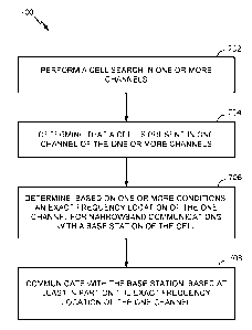
100761 Figure 6 illustrates example operations 600 for wireless
communications, in
accordance with certain aspects of the present disclosure. The operations 600
may be
performed, for example, by a BS (e.g., eNB 110).
[0077] The operations 600 begin, at 602, by the BS determining, based on one
or
more conditions, an exact frequency location of one channel of one or more
channels to
perform narrowband communications with a UE (e.g., UE 120). At 604, the BS
transmits an indication of the one or more conditions to the UE. At 606, the
BS
communicates with the UE, based at least in part on the exact frequency
location of the
one channel.
[0078] Figure 7 illustrates example operations 700 for wireless
communications, in
accordance with certain aspects of the present disclosure. The operations 700
may be
performed, for example, by a UE (e.g., UE 120).
100791 The operations 700 begin, at 702, by the UE performing a cell search in
one or
more channels. In one aspect, the UE may perform the cell search in the one or
more
channels based on the raster frequency. For example, if the raster frequency
is 100 kHz,
the UE may monitor for PSS/SSS every 100 kHz in order to acquire frequency,
timing,
and/or system information. In some cases, the one or more channels in which
the UE
performs the cell search may be based on a rough frequency estimation. At 704,
the UE
determines that a cell is present in one channel of the one or more channels.
At 706, the
UE determines, based on one or more conditions, the exact (or precise)
frequency
location of the one channel for narrowband communications with a base station
of the
cell. At 708, the UE communicates with the base station based at least in part
on the
exact frequency location of the one channel.
[0080] According to certain aspects, the one or more conditions may include a
given
operating bandwidth. In this aspect, the UE and/or BS may determine that there
is one
anchor channel (or resource block) location in which narrowband communications
may
be deployed for a given bandwidth. Once determined, the UE and/or BS may
determine
the exact frequency location by selecting the anchor channel that corresponds
to the
given operating bandwidth. In this manner, the techniques herein can
substantially
reduce the hypothesis for cell searching.
CA 03007298 2018-06-01
WO 2017/123405 PCT/US2016/068467
21
100811 Additionally or alternatively, according to certain aspects, the one or
more
conditions may include a cell identifier (ID). For example, once the UE
determines the
cell ID (e.g., from PSS and SSS), the UE may select the anchor channel
location based
in part, on the cell ID. In one implementation, the UE and/or BS may determine
the
precise anchor location according to the following:
Anchor RB = cell ID mod (number of possible RBs) (1)
where the cell ID is deteimined from PSS and SSS, and wherein the number of
possible
RBs may be based on the system bandwidth. For example, for a system bandwidth
of
20 MHz, there may be four possible RBs (such as RB 0, RB 10, RB 20 and RB 40).
By
using the above equation, the UE may determine the anchor RB being used by the
current cell.
100821 According to certain aspects, there may be more than one anchor RB
defined.
In these cases, the UE may select the anchor RB location from a set of anchor
channels
at or near raster frequency locations. For example, the UE may select the RBs
that are
close to the raster frequency to obtain a first subset of RBs. The UE may then
down-
select the first subset of RBs to obtain a second subset of RBs. In some
cases, the UE
may down-select the first subset of RBs based on the cell ID. In some cases,
the down-
selection may be determined according to a communication standard (e.g.,
defined in a
LTE specification). Once the UE obtains the second subset, the UE may
determine
which RB in the second subset is being used from broadcast signaling (e.g.,
one or more
bits in MIB/SIB, etc.) transmitted by the BS.
100831 According to certain aspects, the network/BS may choose to whether to
use
one fixed anchor RB location for every operating bandwidth or to base the
anchor RB
on its cell ID. In some cases, the BS may decide to use a fixed anchor RB
location in
order to have all narrowband communications deployed in the same frequency. In
some
cases, the BS may decide to use an anchor RB that is based on the cell ID in
order to
reduce inter-cell interference. In either case, the BS may indicate to the UE
the exact
frequency location (e.g., if the BS determines that the anchor RB location
will use a
fixed RB) or indicate to the UE that the UE should determine the exact
frequency
location based on the cell ID. Such indication may be provided via broadcast
signalling
(e.g., 1 bit in PBCH/MIB).
CA 03007298 2018-06-01
WO 2017/123405 PCT/US2016/068467
22
100841 In some cases, the BS may not transmit (or signal) an indication to the
UE as
to how the BS will select the anchor RB location In these cases, the UE can
blindly try
different CRS sequences for the different RBs to determine which RB is used as
the
anchor. For example, when performing the blind detection, the UE may choose
the RB
that has the best correlation with the observed CRS.
[0085] According to some aspects, the one or more conditions may include a
type of
deployment for the narrowband communications. In one aspect, the type of
deployment
may be based on a number of antenna ports used by the BS. The BS, for example,
may
include information about the number of legacy CRS antenna ports in the PBCH,
and
transmit the PBCH to the UE. In one case, if the UE receives an indication
that the
number of antenna ports is greater than 0 (e.g., 1 port, 2 ports, or 4 ports),
the UE may
determine that narrowband communications are being deployed in-band. In one
case, if
the UE receives an indication that the number of antenna ports is 0, the UE
may
determine that narrowband communications are being deployed in dedicated
spectrum
(for a standalone deployment) or in the guard band.
[0086] In certain aspects, the BS may signal an indication of the one or more
conditions via the master information block (MIB) that is transmitted in PBCH.
The
MIB may carry, for example, a 3-bit field that indicates the bandwidth of the
cell;
however all of the values may not be used. For example, in some cases, only 6
values
may be used to indicate the bandwidth According to certain aspects, based on
how the
3 bit field in MIB is interpreted, the UE and/or BS may determine different
types of
information regarding the narrowband communications deployed in cell.
[0087] In one aspect, the BS may use one additional value out of the 6 values
(of the
3-bit field in MIB) to signal a particular bandwidth that indicates standalone
deployment. In one case, for example, the BS may use one additional value to
signal
bandwidth equal to 200 kHz in order to indicate a standalone deployment for
the
narrowband communications. For the guard band case, the BS can provide to the
UE
signalling that indicates the true bandwidth value of the corresponding system
(e.g., 20
MHz in one case for LTE). If the guard-band location is fixed for every
resource block,
then the UE would be able to determine (from the signalling) all the
information it needs
to acquire the cell.
CA 03007298 2018-06-01
WO 2017/123405 PCT/US2016/068467
23
100881 In another aspect, the BS may use the 3-bit field to signal different
types of
information based on the number of antenna ports. The UE, in turn, may also
interpret
the 3 bit field differently based on the number of antenna ports, which may be
signaled
separately by the BS. For example, if the number of antenna ports is greater
than zero
(and thus indicates in-band), the BS may use the 3-bit field to signal the
bandwidth, and
the UE may deteimine (based on the indication of the number of antenna ports)
that the
field signals the bandwidth. In this case, the UE may be able to determine the
absolute
frequency value (e.g., the anchor RB) using any of the above techniques. In
one
example, if the number of antenna ports is equal to zero (and thus indicates
guard band
or standalone), the BS may use the 3-bit field to indicate the frequency
offset with
respect to a frequency grid (e.g., 100 kHz frequency grid), and the UE may
determine
(based on the indication of the number of antenna ports) that the field
signals the offset
with respect to the frequency grid. For example, the BS can signal frequency
offset
values of -7.5, 7.5, -2.5, 2.5, and 0. In this case, signaling a frequency
offset of 0 may
imply a standalone deployment, whereas signalling another value may imply a
guard
band deployment.
[0089] Note that although the aspects presented herein describe the BS
signaling to
the UE various information (e.g., such as antenna ports, frequency offset,
bandwidth,
etc.) in PBCH that the UE may use to determine a frequency location (e.g.,
anchor RB)
and/or type of deployment, such information may also be indicated in other
signals,
such as PSS, SSS, etc., or combination of signals (e.g., split between PSS,
SSS, MIB,
PBCH, and other signals).
100901 As mentioned above, for in-band deployment, the UE may not receive
signaling that indicates the frequency offset, since the UE can derive the
frequency
offset based on an indication of the anchor RB.
100911 According to certain aspects, however, the BS may be configured to
always
signal the frequency offset with respect to the frequency grid (e.g., 100 kHz
grid)
regardless of the deployment type. Thus, in
situations where narrowband
communications are being deployed in-band, the UE may not know which RB is
being
used, which could prevent the UE from using CRS.
CA 03007298 2018-06-01
WO 2017/123405 PCT/US2016/068467
24
[0092] As such, in some aspects, after receiving an indication of the
frequency offset,
the UE may receive an indication of the absolute RB position via a SIB In some
aspects, after receiving an indication of the frequency offset the UE may
receive an
indication of the RB offset plus the anchor RB. In one example, the BS may
signal five
possibilities of the RB offset, which may include +- 2.5, +- 7.5, and 0. In
one example,
the BS may signal three possibilities of the RB offset, which may include >0,
<0, or 0.
[0093] Additionally, in some aspects, if the deployment type is known (e.g.,
by the
BS and/or UE), the guard band offset can be fixed to a constant value. For
example, the
narrowband communications may be fixed to RBs with a center frequency of 7.5
kHz
with respect to the 100 kHz raster. Thus, the guard band may not have to be
aligned
with the physical resource block boundary, but may have to be aligned with the
15 kHz
boundary in order to reuse the same IFFT. Figure 8, for example, illustrates
one
example (for a 3 resource block system) of leaving one or more guard tones to
align
with the frequency raster.
[0094] As shown in Figure 8, in a system 800 including three RBs (e.g., RB 0,
RB 1,
RB 2), the guard band RB 802 is placed at DC + 367.5 kHz. As this frequency is
not
close (e.g., not within some offset) to a raster frequency, the first guard
band RB 802
may not be used for narrowband communications. Aspects of the present
disclosure,
therefore, allow the BS to place one or more guard tones to align the guard
band with a
raster frequency. For example, as also shown in Figure 8, for the guard band
RB 804,
two tones (REs) 806 and 808 (e.g., a 30 kHz gap) are placed in the guard band
RB 804,
so that the center frequency is placed at DC + 397.5 kHz. Because this
frequency is
placed within a 2.5 kHz offset of the raster frequency, the UE can detect the
frequency,
for example, when searching for DC + 400 kHz.
100951 According to certain aspects, the BS may know that the UE is going to
search
for a particular raster frequency (e.g., such as 100 kHz). Thus, in these
cases, the BS
may apply a frequency shift to align transmission of a PSS and a SSS with a
raster
frequency. For example, the BS can apply a fake frequency shift (e.g., +-
2.5kHz, +- 7.5
kHz) such that the frequency estimated from PSS/SSS matches the true
frequency. Put
differently, the BS may attempt to center the sync signal(s) to the raster
frequency.
CA 03007298 2018-06-01
WO 2017/123405 PCT/US2016/068467
100961 In some aspects, if the BS applies a fake frequency shift, the UE, when
decoding PBCH, may shift the PBCH and the corresponding CRS to match the fake
frequency shift (e.g., 2.5 kHz, 7.5 kHz, etc.). In some aspects, the BS may
signal the
shift in SSS, so that the UE can correct the frequency shift before decoding
PBCH.
[0097] In some cases, a small subset of RBs may be allocated using the
techniques
described above. For example, for a 15 RB system, RB index 0 may be at DC, RB
index 1 may be at 187.5 kHz, RB index 2 may be at 367.5 kHz, RB index 3 may be
at
547.5 kHz, RB index 4 may be at 727.5kHz, RB index 5 is at 907.5 kHz, RB index
6 is
at 1087.5 kHz, and RB index 7 is at 1267.5 kHz. In this case, only RB index 5
would
lie close enough to the raster frequency to be detected by a UE.
[0098] According to certain aspects, the BS may apply a tone shift to align
transmission of a PSS and SSS with a raster frequency. For example, a tone
shift can be
applied to the PSS/SSS to allow the UE to detect other additional frequencies
in the
subset of RBs. In one aspect, a tone shift of +- 1 RE (e.g., 15 kHz) can be
applied to the
PSS/SSS. For example, if a tone shift of +15 kHz were applied to each of the
above RB
indexes, RB index 1 would then lie close enough to the raster frequency to be
detected
by UE (e.g., RB index 1 + 15 kHz = 202.5). Similarly, RB index 6 would lie
close
enough to the raster frequency to be detected by the UE (e.g., RB index 6 + 15
kHz =
1102.5).
[0099] In one aspect, the UE may determine the exact frequency location based
on
decoding PSS and SSS. In one aspect, the UE may obtain signaling indicating
the tone
shift and may use the signaled tone shift when decoding a PBCH. For example,
in one
embodiment, after the UE decodes PSS and SSS, the HE may have to resolve the
ambiguity related to the offset, otherwise the UE may not be able to rate
match around
legacy CRS correctly. According to certain aspects, the UE may take one or
more
actions to resolve such ambiguity. In one example, the HE may receive an
indication of
the tone shift via SSS, such that the UE can know the correct CRS puncturing
when
decoding PBCH. In one example, the UE may receive an indication of the tone
shift in
PBCH. However, in order to make PBCH decodable without knowing the position of
legacy CRS, the HE may have legacy CRS puncture PBCH, and the narrowband
reference signal position may take the offset into account. Alternatively,
instead of
CA 03007298 2018-06-01
WO 2017/123405 PCT/US2016/068467
26
receiving signaling that indicates the tone shift, the UE may try different
blind decoding
attempts for different frequency offset hypothesis.
[0100] According to certain aspects, the raster frequencies can be clustered
(e.g., non
uniformly distributed) throughout the system bandwidth. For example, the
frequencies
can be of the form {N*100kHz, N*100kHz + 10 kHz, N*100kHz ¨ 10 kHz}
[0101] According to certain aspects, the NB-IoT channel may be deployed in-
band,
using RBs that are close to the 100kHz raster frequency grid. In this case,
the eNB may
signal the frequency location based on the constraint that only a subset of
the RBs may
be available for NB-IoT transmission.
[0102] Figure 9 illustrates example operations 900 for wireless
communications, in
accordance with certain aspects of the present disclosure. The operations 900
may be
performed, for example, by a BS (e.g., eNB 110).
[0103] The operations 900 begin, at 902, by the BS transmitting to a HE
information
indicative of a frequency location of a channel of one or more channels, a
number of
antenna ports, and a deployment mode for narrowband communications with the
BS.
At 904, the BS communicates with the UE, based at least in part on the
frequency
location of the channel, the number of antenna ports, and the deployment mode.
[0104] Figure 10 illustrates example operations 1000 for wireless
communications,
in accordance with certain aspects of the present disclosure. The operations
1000 may
be performed, for example, by a UE (e.g., UE 120).
101051 The operations 1000 begin, at 1002, by the UL performing a cell search
in one
or more channels At 1004, the UE determines that a cell is present in one
channel of
the one or more channels. At 1006, the UE determines a frequency location of
the one
channel, a number of antenna ports, and a deployment mode for narrowband
communications with a BS of the cell. At 1008, the UE communicates with the
BS,
based at least in part on the frequency location of the one channel, the
number of
antenna ports, and the deployment mode.
[0106] In some aspects, the BS may signal at least one of a deployment mode,
frequency location (or position) of the one channel, a number of CRS antenna
ports or a
CA 03007298 2018-06-01
WO 2017/123405 PCT/US2016/068467
27
same cell ID indicator in the MIB. For example, the BS may use one or more
fields of
the MIB to signal the information to the UE In one aspect, the number of
antenna ports
may be determined based at least in part on a first field in the MIB. The
frequency
location of the channel may be determined based in part on the first field in
the MIB and
second field in the MIB. The deployment mode may be determined based in part
on the
first field in the MIB and second field in the MM.
[0107] In some cases, the one channel may be located in a narrowband region
of
wider system bandwidth, and the UE may use the same cell ID indicator to
determine if
the cell ID of the cell in which the BS is located is the same as a cell ID
for a wideband
cell that uses the wider system bandwidth. Using LTE as a reference example,
the UE
may use the same cell ID indicator to determine if the cell ID for NB-IoT is
the same as
the cell of wideband LTE.
[0108] As noted above, the MIB may include a first field to indicate the
number of
CRS antenna ports. In some cases, the number of CRS antenna ports may be one
of 0,
1, 2 or 4. As noted above, in such cases, signalling 0 CRS antenna ports may
be
interpreted as the deployment being standalone or guard band, and signalling a
positive
number (e.g., greater than 0) of CRS ports may be interpreted as in-band
deployment.
[0109] In one aspect, the MIB may include a second field to indicate a
same/different
physical cell ID (PCID) and may include a third field to indicate the
bandwidth and/or
deployment mode. For example, the second field may be one bit, indicating if
the PCID
is the same (e.g., 1) or different (e.g., 0). The third field may include a
plurality of bits,
and its meaning may depend on the number of CRS antenna ports. For example, if
the
number of CRS antenna ports is 0, this third field may signal the offset with
respect to
the raster frequency (e.g., a multiple of 100kHz) as {-7.5, -2.5, 0, 2.5,
7.5}, with an
offset of 0 meaning standalone deployments and other offset values
corresponding to
guard band deployment. If the number of CRS antenna ports is 1, the third
field may
signal the offset of a resource block with respect to a center frequency.
[0110] In some aspects, determining the frequency location of the channel may
include determining a frequency offset with respect to a raster frequency
based in part
on the second field in the MIB, and determining the frequency position based
in part on
the frequency offset. In some aspects, determining the frequency location of
the
CA 03007298 2018-06-01
WO 2017/123405 PCT/US2016/068467
28
channel may include determining a physical resource block (PRB) position with
respect
to a center frequency of a wideband cell based on the second field in the MIB,
and
determining the frequency location based in part on the PRB position.
[0111] For example, the second field in the MIB may be used to jointly
indicate a
same/different PCID and a frequency/deployment mode. If the number of CRS
ports is
0, then the second field may indicate the offset with respect to raster
frequency as
indicated above. If the number of CRS ports is greater than zero, then a first
subset of
the entries in the second field may be reserved to signal that the PCID is
different, plus
possible offsets (e.g., the 5 noted above) with respect to the raster
frequency. A second
subset of the entries in the second field may be reserved to signal that the
PCID is the
same, and each of the entries in the second subset may signal a PRB location
(or
position) and/or a bandwidth value.
[0112] In one aspect, an additional indication may be included in MIB to
determine
that the deployment is in unlicensed spectrum.
[0113] According to certain aspects, it may be desirable to deploy machine
type
communications (e.g., enhanced or evolved MTC (eIVITC)) and narrowband
communications (e.g., NB-IoT) in the same cell. However, such a deployment may
not
be possible with current agreements for the transmission of broadcast
signalling
(e.g., SIB Ibis transmissions).
[0114] For example, SIB 1 may be hopped per the following agreements Frequency
hopping for SIB ibis may be used at least for system bandwidths greater than
or equal to
MHz SIB is frequency hopping may take place between two or four narrowbands
depending on the system bandwidth. For example, there may be two narrowbands
for a
system bandwidth of 12-50 RBs, and there may be four narrowbands for a system
bandwidth of 51-110 RBs. The narrowbands may be determined based on cell ID
and
system bandwidth. The hopping sequence between these narrowbands may be
determined based on cell ID and subframe index (and/or system frame number
(SFN)).
[0115] The frequency hopping for SIB ibis may be given by:
S = {so, Si, sz, , sk-i}, (2)
CA 03007298 2018-06-01
WO 2017/123405 PCT/US2016/068467
29
101161 where S is a set of valid DL narrowbands s, and k is equal to the
number of
valid narrowbands for SIB Ibis. For system bandwidths less than 12 RBs,
SIBlbis may
be transmitted in narrowband si where j is equal to physical cell identifier
(PCID) mod
k. For system bandwidths between 12-50 RBs, the first narrowband may be si
where j =
PCID mod k, the second narrowband may be (s1 + floor(k/2)) mod k, and the SIB
ibis
transmission may cycle through { lst NB, 2nd NB} starting at SFN mod 8 = 0.
For
system bandwidths between 51-110 RBs, the first narrowband may be si where j =
PCID
mod k, the second narrowband may be (si + floor(k/4)) mod k, the third
narrowband
may be (sj + 2*floor(k/4)) mod k, the fourth narrowband may be (si +
3*floor(k/4)) mod
k, and the SIBlbis transmission may cycle through {14 NB, 211d NB, 3rd N-B,
4th NB I
starting at SFN mod 8 = 0. Additionally, SIB ibis transmissions may be
scheduled in
IVIIB with five spare bits. The TBS and repetition of the SIB ibis
transmission may be
determined from the table illustrated in Figure 11.
[0117] Aspects presented herein provide techniques that allow for deploying,
for
example, eMTC and NB-IoT, in the same cell.
[0118] According to aspects, the eNodeB may determine the particular
implementation of deployment of eMTC operations and narrowband communications
within a cell. In these cases, there may be no change to eMTC operation. In
one case,
for example, the eNodeB may signal the subframes containing SIB ibis as NB-IoT
invalid subframes. This signalling can be RB-specific. Put differently,
different RBs
may have different subframe availability, and the RBs and subframes with SIB
ibis
transmission may be signalled as invalid.
[0119] Additionally or alternatively, in another case, the eNodeB may use
brute force
puncturing to allow for deployment of eMTC operations and narrowband
communications in the same cell. For example, the eNodeB may puncture SIB ibis
by
transmission of NB-IoT RBs. In some cases, the eNodeB may use the least amount
of
resources possible to avoid degradation to eMTC UE reading SIB ibis.
[0120] According to certain aspects, deployment of eMTC and narrowband
communications in the same cell may be possible by re-defining the narrowbands
for
SIBlbis. For example, the set S (shown in equation 2) of SIB ibis narrowbands
s
already excludes the center six RBs. Thus, in one aspect, re-defining the
narrowbands
CA 03007298 2018-06-01
WO 2017/123405 PCT/US2016/068467
for SIB ibis may include removing at least one subset (s,) of the set S that
may contain
NB-Io'T anchor RB, where i is from 0 to k-1. For example, if so (where i = 0)
contains a
NB-IoT RB, then so may be removed from the set S (shown in equation 2). In
some
cases, the removal of a subset s, may be PCID specific (e.g., different PCID
may have
different sets).
[0121] In one aspect, re-defining the narrowbands for SIB ibis may include
removing
subsets s, for a subset of the SIBlbis combinations. For example, new entries
may be
introduced into a SIB ibis table (such as the table illustrated in FIG. 12),
and the subsets
si that may be removed from the set S may be done in accordance with the
entries in the
table.
[0122] Additionally or alternatively, according to certain aspects, deployment
of
eMTC and narrowband communications in the same cell may be possible by
adjusting
NB-IoT physical resource blocks based on SIB ibis. As mentioned above, there
may be
some cases in which the NB-IoT RB (anchor channel location) depends on the
cell ID.
For example, as mentioned above, the anchor RB location may be determined
using
equation 1. In another example mentioned above, there may be more than one
anchor
RB defined, and the UE may down-select from the anchor RB locations based on
the
cell ID.
[0123] In these cases, according to certain aspects, the down-selection may be
based
on PCID as follows. the RBs that are used for SIB ibis eMTC (based on PCID)
may be
discarded; and the remaining RBs may be further down-selected if needed, e.g.,
using
the techniques described.
[0124] According to certain aspects, deployment of eMTC and narrowband
communications in the same cell may be possible using a combination of the
table
illustrated in Figure 12 and adjusting the NB-IoT RBs based on SIB ibis. For
example,
if there are entries in the new SIB Ibis table (e.g., in Figure 12) that do
not remove NB-
IoT, the narrowband RBs (for these entries) may be adjusted based on SIB ibis.
[0125] As used herein, the term "identifying" encompasses a wide variety of
actions.
For example, "identifying" may include calculating, computing, processing,
deriving,
investigating, looking up (e.g., looking up in a table, a database or another
data
CA 03007298 2018-06-01
WO 2017/123405 PCT/US2016/068467
31
structure), ascertaining and the like. Also, "identifying" may include
receiving
(e.g., receiving information), accessing (e.g., accessing data in a memory)
and the like.
Also, "identifying" may include resolving, selecting, choosing, establishing
and the like.
[0126] In some cases, rather than actually communicating a frame, a device may
have
an interface to communicate a frame for transmission or reception. For
example, a
processor may output a frame, via a bus interface, to an RF front end for
transmission.
Similarly, rather than actually receiving a frame, a device may have an
interface to
obtain a frame received from another device. For example, a processor may
obtain (or
receive) a frame, via a bus interface, from an RF front end for transmission.
[0127] The methods disclosed herein comprise one or more steps or actions for
achieving the described method. The method steps and/or actions may be
interchanged
with one another without departing from the scope of the claims. In other
words, unless
a specific order of steps or actions is specified, the order and/or use of
specific steps
and/or actions may be modified without departing from the scope of the claims.
[0128] The various operations of methods described above may be performed by
any
suitable means capable of performing the corresponding functions. The means
may
include various hardware and/or software component(s) and/or module(s),
including,
but not limited to a circuit, an application specific integrated circuit
(ASIC), a processor,
or a processing system. Examples of processors include microprocessors,
mi crocontroll ers, digital signal processors (D SP s), field programmable
gate arrays
(FPGAs), programmable logic devices (PLDs), state machines, gated logic,
discrete
hardware circuits, and other suitable hardware configured to perform the
various
functionality described throughout this disclosure. One or more components
and/or
modules may execute software. Software shall be construed broadly to mean
instructions, instruction sets, code, code segments, program code, programs,
subprograms, software modules, applications, software applications, software
packages,
firmware, routines, subroutines, objects, executables, threads of execution,
procedures,
functions, etc., whether referred to as software, firmware, middleware,
microcode,
hardware description language, or otherwise. Generally, where there are
operations
illustrated in Figures, those operations may be performed by any suitable
corresponding
counterpart means-plus-function components.
CA 03007298 2018-06-01
WO 2017/123405 PCT/US2016/068467
32
101291 For example, means receiving, means for monitoring, and/or means for
communicating may include a receiver, such as receive processor 238, MIMO
detector
236, demodulator(s) 232a-232t, and/or antenna(s) 234a-234t of the base station
110
illustrated in FIG. 2 and/or MIMO detector 256, receive processor 258,
demodulator(s)
254a-254r, and/or antenna(s) 252a-252r of the user equipment 120 illustrated
in FIG. 2.
Means for determining, means for generating, means for monitoring, means for
decoding, means for indicating, means for transmitting, means for
communicating,
means for signaling, means for selecting, and/or means for performing, may
include one
or more processors (or a processing system), such as controller/processor 240,
scheduler
246, transmitter processor 220, receive processor 238, MIMO detector 236, TX
MIMO
processor 230, and/or modulator(s)/demodulator(s) 232a-232t of the base
station 110
illustrated in FIG. 2, and/or controller/processor 280, receive processor 258,
transmit
processor 264, MIMO detector 256, TX MIMO processor 266, and/or
modulator(s)/demodulator(s) 254a-254r of the user equipment 120 illustrated in
FIG. 2.
Means for signaling, means for transmitting, means for communicating and/or
means
for indicating may include a transmitter, such as transmit processor 220, TX
MIMO
processor 230, modulator(s) 232a-232t, and/or antenna(s) 234a-234t of the base
station
110 illustrated in FIG 2, and/or transmit processor 264, TX MIA/10 processor
266,
modulator(s) 254a-254r, and/or antenna(s) 252a-252r of the user equipment 120
illustrated in FIG. 2.
[0130] Those of skill in the art would understand that information and signals
may be
represented using any of a variety of different technologies and techniques.
For
example, data, instructions, commands, information, signals, bits, symbols,
and chips
that may be referenced throughout the above description may be represented by
voltages, currents, electromagnetic waves, magnetic fields or particles,
optical fields or
particles, or combinations thereof.
[0131] Those of skill would further appreciate that the various illustrative
logical
blocks, modules, circuits, and algorithm steps described in connection with
the
disclosure herein may be implemented as electronic hardware, software, or
combinations thereof. To clearly illustrate this interchangeability of
hardware and
software, various illustrative components, blocks, modules, circuits, and
steps have been
described above generally in terms of their functionality. Whether such
functionality is
CA 03007298 2018-06-01
WO 2017/123405 PCT/US2016/068467
33
implemented as hardware or software depends upon the particular application
and
design constraints imposed on the overall system. Skilled artisans may
implement the
described functionality in varying ways for each particular application, but
such
implementation decisions should not be interpreted as causing a departure from
the
scope of the present disclosure.
[0132] The various illustrative logical blocks, modules, and circuits
described in
connection with the disclosure herein may be implemented or performed with a
general-
purpose processor, a digital signal processor (DSP), an application specific
integrated
circuit (ASIC), a field programmable gate array (FPGA) or other programmable
logic
device, discrete gate or transistor logic, discrete hardware components, or
any
combination thereof designed to perform the functions described herein. A
general-
purpose processor may be a microprocessor, but in the alternative, the
processor may
be, for example, any conventional processor, controller, microcontroller,
FPGA, PLD,
DSP, state machine, etc. A processor may also be implemented as a combination
of
computing devices, e.g., a combination of a DSP and a microprocessor, a
plurality of
microprocessors, one or more microprocessors in conjunction with a DSP core,
or any
other such configuration.
101331 The steps of a method or algorithm described in connection with the
disclosure
herein may be embodied directly in hardware, in a software module executed by
a
processor, or in a combination thereof. A software module may reside in RAM
memory, flash memory, ROM memory, EPROM memory, EEPROM memory, phase
change memory, registers, hard disk, a removable disk, a CD-ROM, or any other
form
of storage medium known in the art. An exemplary storage medium is coupled to
the
processor such that the processor can read information from, and write
information to,
the storage medium. In the alternative, the storage medium may be integral to
the
processor. The processor and the storage medium may reside in an ASIC. The
ASIC
may reside in a user terminal. In the alternative, the processor and the
storage medium
may reside as discrete components in a user terminal.
101341 In one or more exemplary designs, the functions described may be
implemented in hardware, software, or combinations thereof. If implemented in
software, the functions may be stored on or transmitted over as one or more
instructions
or code on a computer-readable medium. Computer-readable media includes both
CA 03007298 2018-06-01
WO 2017/123405 PCT/US2016/068467
34
computer storage media and communication media including any medium that
facilitates transfer of a computer program from one place to another. A
storage media
may be any available media that can be accessed by a general purpose or
special
purpose computer. By way of example, and not limitation, such computer-
readable
media can comprise RAM, ROM, EEPROM, CD/DVD or other optical disk storage,
magnetic disk storage or other magnetic storage devices, or any other medium
that can
be used to carry or store desired program code means in the form of
instructions or data
structures and that can be accessed by a general-purpose or special-purpose
computer,
or a general-purpose or special-purpose processor. Also, any connection is
properly
termed a computer-readable medium. For example, if the software is transmitted
from a
website, server, or other remote source using a coaxial cable, fiber optic
cable, twisted
pair, digital subscriber line (DSL), or wireless technologies such as
infrared, radio, and
microwave, then the coaxial cable, fiber optic cable, twisted pair, DSL, or
wireless
technologies such as infrared, radio, and microwave are included in the
definition of
medium. Disk and disc, as used herein, includes compact disc (CD), laser disc,
optical
disc, digital versatile disc (DVD), floppy disk and Blu-ray disc where disks
usually
reproduce data magnetically, while discs reproduce data optically with lasers.
Combinations of the above should also be included within the scope of computer-
readable media.
[0135] As used herein, reference to an element in the singular is not intended
to mean
"one and only one" unless specifically so stated, but rather "one or more."
For example,
the articles "a" and "an" as used in this application and the appended claims
should
generally be construed to mean "one or more" unless specified otherwise or
clear from
the context to be directed to a singular form. Unless specifically stated
otherwise, the
term "some" refers to one or more. As used herein, the term "and/or," when
used in a
list of two or more items, means that any one of the listed items can be
employed by
itself, or any combination of two or more of the listed items can be employed.
For
example, if a composition is described as containing components A, B, and/or
C, the
composition can contain A alone; B alone; C alone; A and B in combination; A
and C in
combination; B and C in combination; or A, B, and C in combination. Also, as
used
herein, including in the claims, "or" as used in a list of items (for example,
a list of
items prefaced by a phrase such as "at least one of' or "one or more of')
indicates a
disjunctive list such that, for example, a list of "at least one of A, B, or
C" means A or B
CA 03007298 2018-06-01
WO 2017/123405 PCT/US2016/068467
or C or AB or AC or BC or ABC ("ABC" indicating A and B and C), as well as any
combination with multiples of the same element (e g , AA, AAA, ABB, AAC, ABBCC
or any other ordering of A, B, C).
[0136] The previous description of the disclosure is provided to enable any
person
skilled in the art to make or use the disclosure. Various modifications to the
disclosure
will be readily apparent to those skilled in the art, and the generic
principles defined
herein may be applied to other variations without departing from the spirit or
scope of
the disclosure. Thus, the disclosure is not intended to be limited to the
examples and
designs described herein but is to be accorded the widest scope consistent
with the
principles and novel features disclosed herein.