Note: Descriptions are shown in the official language in which they were submitted.
PATENT
Docket No. 0256.0002
DUAL-STAGE SEPARATOR
Cross-Reference to Related Applications
[0001] This application claims priority to U.S. Provisional Patent Application
No. 62/518,324,
filed on June 12, 2017, the entirety of which is hereby incorporated by
reference.
Background
[0002] Gas resources such as shale are accessed using a process called
hydraulic fracturing or
"fracking." The fracturing process begins with the drilling of a well into a
rock formation. This
technique further involves injecting a mixture of water, sand, and a small
amount of other additives
(e.g., a blend of chemicals) into the well. These fluids are typically made up
of about 90% water
and 9.5% sand. Many of the ingredients in the remaining 0.5% of the mixture
have common
consumer applications in household products, detergents, and cosmetics. These
chemicals are
used to reduce friction, prevent bacteria growth, and protect the rock
formation, making the
hydraulic fracturing safer and more efficient.
[0003] The well equipment used to produce oil from the well typically includes
components that
are designed to separate the unwanted substances from the oil. For instance, a
conventional sand
separator is commonly provided at the surface of the well to remove the sand
that may be present
in the oil.
[0004] There are various problems with the use of the conventional sand
separator to remove
sand from oil or other fluids, which may be amplified because the fluids are
being produced under
high pressure and at high volumes. Therefore, there is a need for an improved
separator.
Summary
[0001] In one aspect, an apparatus for removing particles from a fluid is
provided. The apparatus
includes a pressure vessel having an inlet and an outlet. A centrifuge is
disposed in the pressure
vessel. The centrifuge is configured to remove a first portion of particles
from the fluid. A cyclone
separator is also disposed in the pressure vessel, such that the centrifuge
extends around the
cyclone separator. The cyclone separator includes an array of cyclones
configured to remove a
second portion of particles from the fluid.
1
CA 3007832 2018-06-12
PATENT
Docket No. 0256.0002
[0002] In another aspect, a method of removing particles from a multi-phase
fluid is provided.
The method includes placing a dual-stage separator in fluid communication with
a source of the
multi-phase fluid. The dual-stage separator includes a centrifuge and a
cyclone separator. The
centrifuge is positioned around and upstream of the cyclone separator. The
cyclone separator
includes an array of cyclones. A first portion of particles is removed as the
multi-phase fluid
passes through the centrifuge. A second portion of particles is removed as the
multi-phase fluid
passes through the cyclone separator.
[0003] In yet another aspect, an apparatus for removing solid particles from a
multi-phase fluid
flow is provided. The apparatus includes a cylindrical high-pressure vessel
with a vertical axis. A
centrifuge is disposed within the high-pressure vessel at a location that is
concentric with the
vertical axis of the vessel. An array of cyclones is also disposed within the
high-pressure vessel
at a location that is concentric with the vertical axis of the vessel. The
centrifuge is positioned
around the cyclones. An inlet of the high-pressure vessel is directed
tangentially into an annular
space formed between an inner surface of the high-pressure vessel and an outer
surface of the
cyclones. An inlet of each cyclone is in communication with an innermost flow
path of the annular
space.
Brief Description of the Drawings
[0004] The present disclosure may best be understood by referring to the
following description
and accompanying drawings that are used to illustrate embodiments of the
invention. In the
drawings:
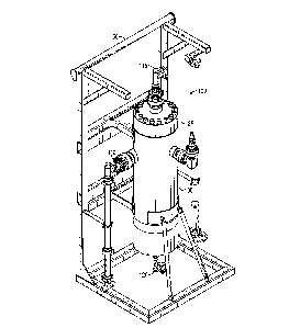
[0005] Figure 1 illustrates a perspective view a dual-stage separator,
according to an
embodiment.
[0006] Figure 2 illustrates a side view of the dual-stage separator and a
support member,
according to an embodiment.
[0007] Figure 3 illustrates another side view of the dual-stage separator,
according to an
embodiment.
[0008] Figure 4 is a sectional view taken along line 4-4 in Figure 3.
[0009] Figure 5 is a sectional view taken along line 5-5 in Figure 3.
[0010] Figure 6 is a sectional view taken along line 6-6 in Figure 3.
2
CA 3007832 2018-06-12
PATENT
Docket No. 0256.0002
[0011] Figure 7 illustrates a side view of a second stage of the dual-stage
separator, according to
an embodiment.
[0012] Figure 8 illustrates a sectional view taken along line 8-8 in Figure 7.
[0013] Figure 9 illustrates a sectional view taken along line 9-9 in Figure 7.
[0014] Figure 10 illustrates a flowchart of a method for removing particles
from a multi-phase
fluid, according to an embodiment.
[0015] Figure 11 illustrates a side view of a second stage of the dual-stage
separator, according
to an embodiment.
[0016] Figure 12 illustrates a sectional view taken along line 12-12 in Figure
11.
[0017] Figure 13 illustrates a sectional view taken along line 13-13 in Figure
11.
[0018] Figure 14 illustrates a top view of a cyclone separator, according to
an embodiment.
[0019] Figure 15 illustrates a sectional view taken along line 15-15 in Figure
14.
[0020] Figure 16 illustrates a side view the dual-stage separator with a water
level device,
according to an embodiment.
[0021] Figure 17 illustrates a flowchart of another method for removing
particles from a multi-
phase fluid, according to an embodiment.
Detailed Description
[0022] The following disclosure describes several embodiments for implementing
different
features, structures, or functions of the invention. Embodiments of
components, arrangements,
and configurations are described below to simplify the present disclosure;
however, these
embodiments are provided merely as examples and are not intended to limit the
scope of the
invention. Additionally, the present disclosure may repeat reference
characters (e.g., numerals)
and/or letters in the various embodiments and across the Figures provided
herein. This repetition
is for the purpose of simplicity and clarity and does not in itself dictate a
relationship between the
various embodiments and/or configurations discussed in the Figures. Moreover,
the formation of
a first feature over or on a second feature in the description that follows
may include embodiments
in which the first and second features are formed in direct contact, and may
also include
embodiments in which additional features may be formed interposing the first
and second features,
such that the first and second features may not be in direct contact. Finally,
the embodiments
presented below may be combined in any combination of ways, e.g., any element
from one
3
CA 3007832 2018-06-12
PATENT
Docket No. 0256.0002
exemplary embodiment may be used in any other exemplary embodiment, without
departing from
the scope of the disclosure.
[0023] Additionally, certain terms are used throughout the following
description and claims to
refer to particular components. As one skilled in the art will appreciate,
various entities may refer
to the same component by different names, and as such, the naming convention
for the elements
described herein is not intended to limit the scope of the invention, unless
otherwise specifically
defined herein. Further, the naming convention used herein is not intended to
distinguish between
components that differ in name but not function. Additionally, in the
following discussion and in
the claims, the terms "including" and "comprising" are used in an open-ended
fashion, and thus
should be interpreted to mean "including, but not limited to." All numerical
values in this
disclosure may be exact or approximate values unless otherwise specifically
stated. Accordingly,
various embodiments of the disclosure may deviate from the numbers, values,
and ranges disclosed
herein without departing from the intended scope. In addition, unless
otherwise provided herein,
"or" statements are intended to be non-exclusive; for example, the statement
"A or B" should be
considered to mean "A, B, or both A and B."
[0024] In general, embodiments of the present disclosure provide an apparatus
for removing
particles from a multi-phase fluid by using a two stage process. In the first
stage, a centrifuge
removes a first portion of (e.g., large and/or dense) particles from the multi-
phase fluid. In the
second stage, an array of small cyclone separators remove a second portion of
(e.g., smaller)
particles from the multi-phase fluid. The particles in the first portion may
have a larger average
cross-sectional dimension (e.g., diameter) than the particles in the second
portion.
[0025] Turning now to the specific, illustrated embodiments, Figures 1 and 2
illustrate a dual-
stage separator 100 in a support member 50, according to an embodiment. The
dual-stage
separator 100 includes a pressure vessel 105 having an inlet 110, an outlet
115, and a particle
cleanout valve 120. The pressure vessel 105 further includes an access flange
125 configured to
be removable to access components inside the pressure vessel 105. In one
embodiment, the
pressure vessel 105 has a cylindrical shape. As will be described herein, the
dual-stage separator
100 is configured to remove particles (e.g., sand and/or other solid
particles) out of a multi-phase
fluid using a two-stage process.
[0026] Figure 3 illustrates a side view of the dual-stage separator 100 with
the support member
50 omitted (for clarity), and Figure 4 is a sectional view taken along line 4-
4 in Figure 3. The inlet
4
CA 3007832 2018-06-12
PATENT
Docket No. 0256.0002
110 is in fluid communication with an interior 90 of the pressure vessel 105.
The dual-stage
separator 100 includes a first stage 190 and a second stage 150. The first
stage 190 includes a
centrifuge 195 that is configured to remove a first portion of (e.g., large
dense) particles from the
multi-phase fluid. The second stage 150 includes a cyclone separator 130 that
is configured to
remove a second portion of (e.g., smaller) particles from the multi-phase
fluid. In at least one
embodiment, the second stage 150 may positioned downstream from and/or occur
after the first
stage 190.
[0027] As also shown in Figure 4, the pressure vessel 105 includes a particle
collection chamber
135 that receives the first portion of (e.g., large and/or dense) particles
that are removed by the
centrifuge 195 and/or the second portion of (e.g., smaller) particles that are
removed by the cyclone
separator 130. The particles may be removed from the particle collection
chamber 135 by opening
the valve 120. The particles may be sand and/or other solids that were in the
multi-phase fluid.
[0028] Figure 5 is a sectional view taken along line 5-5 in Figure 3. As shown
in Figure 5, the
cyclone separator 130 (i.e., the second stage 150) is disposed within the
pressure vessel 105.
Figure 6 is a sectional view taken along line 6-6 on Figure 3. As shown in
Figure 6, the centrifuge
195 (i.e., the first stage 190) is disposed within the pressure vessel 105.
The centrifuge 195 is
defined between the interior 90 of the pressure vessel 105 and an exterior
surface of the cyclone
separator 130. Also shown in Figure 6 is the tangent entry of the inlet 110 of
the dual-stage
separator 100. This tangent entry generates the rotational flow of the multi-
phase fluid around the
first stage 190 creating a primary centrifugal separation zone.
[0029] Figure 7 illustrates a side view of the cyclone separator 130,
according to an embodiment.
The cyclone separator 130 includes a fluid outlet 175 and a plurality/array of
cyclones 170. Each
cyclone 170 has an inlet 155 and a particle outlet 160. The inlet(s) 155
allow(s) the partially
separated multi-phase fluid from the first stage 190 to enter the cyclone(s)
170 at the vector of the
fluid velocity.
[0030] Figure 8 illustrates a sectional view taken along line 8-8 in Figure 7.
As shown in Figure
8, each cyclone 170 includes a tube 165 connected to an outlet manifold 180 of
the cyclone
separator 130. Multi-phase fluid enters into the inlet(s) 155 (see Figure 7)
and flows around an
interior of the cyclone(s) 170, which causes the second portion of particles
to drop out of the fluid
toward the particle outlet 160. At substantially the same time, clean fluid
flows through the tube
165 and into the outlet manifold 180 of the cyclone separator 130 and
subsequently flows out of
CA 3007832 2018-06-12
PATENT
Docket No. 0256.0002
the fluid outlet 175. As used herein, "clean fluid" refers to the multi-phase
fluid after the first
portion of particles and/or the second portion of particles have been removed.
The fluid outlet 175
of the cyclone separator 130 is in fluid communication with the outlet 115 of
the dual-stage
separator 100 (see Figure 4).
[0031] In at least one embodiment, the multi-phase fluid may enter the
cyclones 170 through the
inlet(s) 155 and the particle outlet(s) 160. More particularly, in some
situations, the cyclones 170
may be configured such that the multi-phase fluid may flow up into the
cyclones 170 through the
particle outlet(s) 160 at substantially the same time as the multi-phase fluid
flows into the cyclones
170 through the inlet(s) 155. Thus, the particle outlet(s) 160 may have the
multi-phase fluid flow
(e.g., upward) therethrough and (e.g., simultaneously) have the second portion
of the particles
flow/fall (e.g., downward) therethrough.
[0032] Figure 9 illustrates a sectional view taken along line 9-9 in Figure 7.
As shown in Figure
9, the cyclone separator 130 includes six individual cyclones 170 that are
circumferentially-offset
from one another. However, it should be noted that the cyclone separator 130
may include any
number of cyclones 170 (e.g., 2, 3, 4, 5, 6, or 7) without departing from the
scope of the disclosure.
The selection of the number of cyclones 170 may be based upon the amount of
production volume
from the well. For instance, if the production volume is low, then less
cyclones 170 may be needed.
If the production volume is high, then more cyclones 170 may be needed. The
number of cyclones
170 may be used to optimize performance of the dual-stage separator 100 based
upon well fluid
proportions. Each cyclone 170 includes the inlet 155 and the tube 165. As
shown, the tangential
arrangement of the inlet 155 and the alignment with the flow vector from the
first stage 190 ensure
turbulence is kept to a minimum and the flow paths remain smooth and laminar.
[0033] Figure 10 illustrates a flowchart of a method 1000 for removing
particles from a multi-
phase fluid, according to an embodiment. The method 1000 may include
introducing multi-phase
fluid into the dual-stage separator 100 through the inlet 110, as at 1002. The
multi-phase fluid
may then flow into the first stage 190 (i.e., the centrifuge 195).
[0034] The method 1000 may also include removing a first portion of (e.g.,
large dense) particles
from the multi-phase fluid in the first stage 190 using the centrifuge 195, as
at 1004. More
particularly, as the multi-phase fluid travels through the circular path of
the centrifuge 195, the
first portion of particles in the multi-phase fluid may contact the interior
wall 90 of the pressure
vessel 105 and drop into the particle collection chamber 135 of the pressure
vessel 105. The
6
CA 3007832 2018-06-12
PATENT
Docket No. 0256.0002
remainder of the multi-phase fluid may flow into the second stage 150 (i.e.,
the cyclone separator
130).
[0035] The method 1000 may also include removing a second portion of (e.g.,
smaller) particles
from the multi-phase fluid in the second stage 150 using the cyclone separator
130, as at 1006.
More particularly, in the second stage, the remainder of the multi-phase fluid
flows into the
cyclones 170 (via the inlet 155) and around the interior of the cyclone 170,
which causes the second
portion of particles to drop out of the fluid, toward the particle outlet 160,
and into the particle
collection chamber 135. The clean fluid in the cyclone 170 flows through the
tube 165 and into
the outlet manifold 180 of the cyclone separator 130 and subsequently out of
the fluid outlet 175.
The clean fluid then flows out of the fluid outlet 175 and to the outlet 115
of the dual-stage
separator 100.
[0036] Figure 11 illustrates a view of an alternative second stage 250 of the
dual-stage separator
100, according to an embodiment. The second stage 250 has a substantially
similar function as
the second stage 150 described above. For example, the second stage 250
includes a cyclone
separator 230 that includes a plurality of cyclones 270.
[0037] Figure 12 illustrates a sectional view taken along line 12-12 in Figure
11. As shown in
Figure 12, each cyclone 270 has an inlet 255 connected to an inlet manifold
245. Further, each
cyclone 270 includes a tube 265 in fluid communication with the outlet 115 of
the dual-stage
separator 100. Additionally, each cyclone 270 includes a particle outlet 260
that is in
communication with the particle collection chamber 135 of the dual-stage
separator 100.
[0038] Figure 13 illustrates a sectional view taken along line 13-13 in Figure
11. As shown in
Figure 13, the cyclone separator 230 includes six individual cyclones 270 that
are
circumferentially-offset from one another. As discussed above, it should be
noted that the cyclone
separator 230 may include any number of cyclones 270 (e.g., 2, 3, 4, 5, 6, or
7) without departing
from the principles of the invention. The selection of the number of cyclones
270 may be based
upon the amount of production volume from the well. For instance, if the
production volume is
low, then less cyclones 270 may be needed. If the production volume is high,
then more cyclones
270 may be needed. The number of cyclones 270 may be used to optimize
performance of the
dual-stage separator based upon well fluid proportions.
[0039] Figure 14 illustrates a top view of the cyclone separator 230,
according to an embodiment.
The inlet manifold 245 includes an inlet flow vane (also known as a stator)
225. Figure 15
7
CA 3007832 2018-06-12
PATENT
Docket No. 0256.0002
illustrates a sectional view taken along line 15-15 in Figure 14. As shown on
Figure 15, the inlet
255 of the cyclone 270 is connected to the inlet manifold 245. Multi-phase
fluid enters the inlet
flow vane 225 of the inlet manifold 245. Next, the multi-phase fluid flows
from the inlet manifold
245 into each cyclone 270 via the inlet 255. Thereafter, the multi-phase fluid
flows around an
interior of the cyclone 270, which causes particles to drop out of the fluid
toward the particle outlet
260. At substantially the same time, the clean fluid flows through the tube
265 and subsequently
out of the outlet 115 of the dual-stage separator 100.
[0040] Figure 16 illustrates a side view the dual-stage separator 100 with a
water level device
300, according to an embodiment. The water level device 300 includes a drain
tube 305, optional
baffles 310, and an optional float valve 315. The float valve 315 may allow
heavier liquids to flow
into the drain tube 305 while substantially preventing gas-phase fluid from
flowing into the drain
tube 305. Generally, the water level device 300 is configured to maintain a
predetermined water
level in the pressure vessel 105.
[0041] Figure 17 illustrates a flowchart of another method 1700 for removing
particles from a
multi-phase fluid, according to an embodiment. The method 1700 may include
introducing multi-
phase fluid into the dual-stage separator 100 through the inlet 110, as at
1702. Next the multi-
phase fluid enters the first stage 190 (i.e., the centrifuge 195).
[0042] The method 1700 may also include removing a first portion of (e.g.,
large dense) particles
from the multi-phase fluid in the first stage 190 using the centrifuge 195, as
at 1704. More
particularly, as the multi-phase fluid flows through the circular path of the
centrifuge 195, the first
portion of particles may contact the interior wall 90 of the pressure vessel
105 and drop into the
particle collection chamber 135 of the pressure vessel 105. The remainder of
the fluid may flow
into the second stage 150 (i.e., the cyclone separator 130).
[0043] The method 1700 may also include removing a second portion of (e.g.,
smaller) particles
from the multi-phase fluid in the second stage 150 using the cyclone separator
130, as at 1706.
More particularly, in the second stage, the remainder of the multi-phase fluid
flows into the
cyclones 170 (via the inlet 155) and around the interior of the cyclone 170,
which causes second
portion of particles to drop out of the fluid, toward the particle outlet 160,
and into the particle
collection chamber 135. The clean fluid flows through the tube 165 and into
the outlet manifold
180 of the cyclone separator 130 and subsequently out of the fluid outlet 175.
The clean fluid the
flows out of the fluid outlet 175 and to the outlet 115 of the dual-stage
separator 100.
8
CA 3007832 2018-06-12
PATENT
Docket No. 0256.0002
[0044] In some situations, fluid (e.g., water) may fill a portion of the
pressure vessel 105 which
may cause the dual-stage separator 100 to function inefficiently. The method
1700 may also
include controlling the water level in the pressure vessel 105 using the water
device 300, as at
1708. This may include maintaining the water level below a predetermined
level. More
particularly, as the water level in the pressure vessel 105 reaches a
predetermined level, the float
valve 315 opens to allow the water to drain out of the drain tube 305. The
baffles 310 in the
pressure vessel 105 are configured to create a tortuous path for the particles
in the particle
collection chamber 135 such that the fluid in pressure vessel 105 flows out
the drain tube 305
rather than the particles. In some embodiments, the water device 300 may
operate without the use
of the float valve 315 by positioning the inlet of the drain tube 305 at a
predetermined location of
the pressure vessel 105 such that water flows into the drain tube 305 when the
water level reaches
the inlet of the drain tube 305.
[0045] As used herein, the terms "inner" and "outer"; "up" and "down"; "upper"
and "lower";
"upward" and "downward"; "above" and "below"; "inward" and "outward"; "uphole"
and
"downhole"; and other like terms as used herein refer to relative positions to
one another and are
not intended to denote a particular direction or spatial orientation. The
terms "couple," "coupled,"
"connect," "connection," "connected," "in connection with," and "connecting"
refer to "in direct
connection with" or "in connection with via one or more intermediate elements
or members."
[0046] The foregoing has outlined features of several embodiments so that
those skilled in the
art may better understand the present disclosure. Those skilled in the art
should appreciate that
they may readily use the present disclosure as a basis for designing or
modifying other processes
and structures for carrying out the same purposes and/or achieving the same
advantages of the
embodiments introduced herein. Those skilled in the art should also realize
that such equivalent
constructions do not depart from the spirit and scope of the present
disclosure, and that they may
make various changes, substitutions, and alterations herein without departing
from the spirit and
scope of the present disclosure.
9
CA 3007832 2018-06-12