Note: Descriptions are shown in the official language in which they were submitted.
CA 03007934 2018-06-08
WO 2017/098401
PCT/IB2016/057374
"APPARATUS AND PROCESS FOR SEPARATING THROUGH
FOAM"
DESCRIPTION
FIELD OF APPLICATION
The present invention relates to an apparatus and a process for foam
separation, which can be used for separating substances having different
hydrophobicity, e.g. for separating particles, particularly for mineral
treatment purposes, e.g. for treating coal, as well as for environmental,
recycling and water treatment purposes, in order to attain separation
between solids, between solid and liquid, or between liquids.
BACKGROUND ART
Foam separation machines are known, which are also called foam
separation cells, wherein separation between elements can be made to
occur by exploiting the hydrophilic or hydrophobic characteristics of
specific elements. In the mining industry, such machines are known as
flotation cells. Separation cells generally collect a liquid flow containing
the substances to be separated, which is also referred to as pulp when it
also includes solids, and gas and/or air bubbles are generated and/or
injected, which tend to separate the hydrophobic material from the
hydrophilic material.
The hydrophobic material adheres to the bubbles and is transported
towards the liquid-air interface, thus generating foams that will tend to
aggregate and accumulate in the upper part of the cell, while the
hydrophilic material will remain in the pulp to be then drained, for
1
CA 03007934 2018-06-08
WO 2017/098401
PCT/IB2016/057374
example, at the bottom.
Different types of foam separation cells have been developed, the best
known and most common ones being the following:
- mechanical separation cells;
- column-type separation cells, also called separation columns;
- pneumatic separation cells;
- induced and dissolved air flotation (DAF).
Said separation cells operate in a gravitational field, and the force that
causes the separation between foams and pulp is the gravitational force.
Centrifugal cells have also been developed, wherein the force that
produces the separation between foams and pulp is a centrifugal force.
Centripetal acceleration can be obtained by feeding the material and the
pulp tangentially into the cell, or it can be generated, for example, by
turning the body of the foam separation cell about an axis of rotation.
Reagents can be added to the pulp in order to promote separation,
improve foam stability, increase the hydrophobicity of the materials that
need to be recovered, and reduce the hydrophobicity of those materials
that must not be present in the foams.
For example, greater foam thicknesses, or tall foams, can be obtained by
using a large amount of frother or more persistent frothers. Larger frother
quantities can improve the foam separation results, but generally also
have some adverse effects on other parts of the plant and on the
environment.
A foam separation cell is typically a process unit integrated into a plant,
and very often larger frother quantities will reduce the overall efficiency
2
CA 03007934 2018-06-08
WO 2017/098401
PCT/IB2016/057374
of the system. Environmental constraints may also limit the type and
quantity of reagents that can be used for foam separation, and the effluent
may have to be completely treated and then recirculated, resulting in
higher production costs.
Mechanical foam separation cells generally consist of walls that define a
treatment chamber into which the pulp or liquid is fed. The pulp is kept in
agitation by an impeller. The motion of the impeller, combined with the
stator, transforms the forced air taken in at base of the rotor into small
bubbles through the effect of shearing forces.
Foam separation columns are known which include, typically in their
lower part, air-bubble generators that introduce bubbles which, as they
rise, intercept the hydrophobic substances in the pulp and carry them
upwards. Separation columns are generally also provided with a foam
washing assembly to improve foam purity, so that a purer product
concentrate can generally be obtained.
In centrifugal separation cells, which generally have a circular shape, the
pulp with the material to be separated is fed tangentially in order to
impart thereto a centrifugal acceleration. Air transformed into tiny
bubbles, e.g. through a Venturi tube, is injected into the material and pulp
supply duct.
Mechanical cells have shown that they can ensure good results in terms
of hydrophobic material recovery, but they can hardly give highly pure
foam concentrates.
Separation columns and pneumatic cells produce taller foams than
mechanical cells, and the foams can be washed to remove the impurities
3
CA 03007934 2018-06-08
WO 2017/098401
PCT/IB2016/057374
contained in the liquid between the bubbles to obtain higher purity.
Centrifugal cells have a greater unitary capacity than the other types of
foam separation cells, but they are less efficient in terms of separation.
It has been demonstrated that separation selectivity increases with foam
height; for this reason, thicker foams in the foam separation cells will
give purer products not just because of foam washing, as is the case of
the above-mentioned foam separation columns.
One drawback of the separation cells known in the art is that the depth of
the foams reduces the stability thereof, which should be understood as the
property of the bubbles of not collapsing.
If the bubbles do not collapse, a certain stability and height of the foams
can be obtained which will allow them to continuously reach the intended
drain, so that the hydrophobic material can be effectively separated and
recovered.
It is one object of the present invention to provide an apparatus for foam
separation of hydrophobic substances which allows increasing the height
of the foams while preventing them from collapsing.
It is another object of the present invention to provide an apparatus for
foam separation of particles, which can be used with any type of foam
separation cell known in the art to improve the efficiency of the single
foam separation cells and of the whole plant.
It is a further object to provide an apparatus which is simple to install on
and/or remove from the foam separation cells and which allows for
simple and fast maintenance.
It is a further object to set up a process for foam separation of
4
CA 03007934 2018-06-08
WO 2017/098401
PCT/IB2016/057374
hydrophobic substances which ensures a more effective separation
between hydrophobic and hydrophilic materials as well as larger amounts
of foams, in particular taller foams than can be obtained by the prior art.
Last but not least, it is yet another object of the invention to provide a
.. method and/or a device for detecting the properties of the foam during a
separation process.
With a view to overcome the shortcomings of the prior art and to achieve
these and further objects and advantages, the present Applicant has
conceived, tested and implemented the present invention.
DESCRIPTION OF THE INVENTION
The present invention is set out and characterized in the independent
claims. Dependent claims disclose other features of the present invention
or variations of the principal inventive idea.
In accordance with the above-mentioned objects, an apparatus for foam
separation comprises a foam separation cell and at least one modular
foam support element which can be associated with said foam separation
cell, preferably in a movable and/or removable manner during the
separation process.
Advantageously, the apparatus for foam separation comprises a plurality
.. of modular elements mutually associated to define a three-dimensional
structure having large containment and support volumes that provide a
large additional support surface for the foams.
Said support structure may have a constant or variable section along one
or more development directions.
.. The modular elements may be shaped as sheets, the thickness of which is
5
CA 03007934 2018-06-08
WO 2017/098401
PCT/IB2016/057374
much smaller than the dimensions that define the surface development, or
they may have an elongated shape with one prevalent dimension, e.g.
elongated and/or filiform elements, or small-diameter hollow tubes.
The modular elements may have, in a front view, an oval, circular,
square, polygonal, regular or irregular shape, or any other possible shape.
The modular elements may have a substantially flat shape, or they may be
curved about one or more axes, or be partly flat and partly curved.
The modular elements may have a constant or variable section along a
longitudinal or transverse development.
The modular elements may be arranged parallel to the vertical
development of the foam separation cell, or they may be oblique,
organized in parallel and/or transverse rows, or arranged in a sunburst
pattern or in variable-diameter concentric rings.
For example, the modular elements may be mutually aligned, concentric
or oblique.
In some embodiments, the modular elements can be combined together in
relation to the average size of the bubbles and/or to the size of the
material particles to be separated.
The modular elements may be solid, or they may have through holes or
slots to allow the foams and/or pulp or liquid to move in a lateral
direction. In this manner, the apparatus can still operate even when one or
more foam passage volumes have been obstructed by the material
contained therein.
In some embodiments, the apparatus comprises a foam support module
defined by one or a plurality of mutually associated modular elements.
6
CA 03007934 2018-06-08
WO 2017/098401
PCT/IB2016/057374
The foam support module has peripheral surfaces and inner surfaces. The
inner surfaces are defined by a plurality of mutually combined modular
elements. The outer surfaces may be defined by the same modular
elements, or an enclosure may be provided to enclose said modular
elements.
In some embodiments, the foam support modules may comprise a
dedicated device for air recirculation and introduction and bubble
generation for increased total bubble production, resulting in taller foams.
In some variant embodiments, which can be combined with other
embodiments, the foam support modules can be associated with washing
devices, which may be either connected to or distinct from the washing
system included, for example, in column-type cells, thus allowing for
improved foam washing and rinsing.
The modular elements and/or the foam support modules can be applied to
any existing type of foam separation cell. They can also be integrated by
design into new machines.
At any rate, preferably, the modular elements and/or the foam support
modules can be installed in a movable and/or removable manner also
during the separation process, so that they can be moved or removed in
order to take foam samples or to carry out maintenance, cleaning or
replacement work and the like.
In some embodiments, the modular elements and/or the foam support
modules are installed in the upper part of the foam separation cells, and
can be partly placed inside the pulp or on top of it. The modular elements
and/or the foam support modules may be applied to the edge of a foam
7
CA 03007934 2018-06-08
WO 2017/098401
PCT/IB2016/057374
separation cell or associated therewith, or suspended with respect to the
pulp.
The modular elements and/or the foam support modules can be so
arranged as to cover the whole free surface of the interface between the
liquid containing the material to be separated and the foams of a foam
separation cell, or only a part thereof
The foams can be collected by overflow from the top of the foam support
modules, or through drain channels leading to collection tanks or
collectors, or they may be transferred through connection pipes into a
subsequent foam support module, and the concentrate may be taken from
the last foam support module of the series.
According to a preferred possible embodiment, the invention comprises a
device for taking foam samples, so that foam properties can be detected,
such as composition, purity and the like.
BRIEF DESCRIPTION OF THE DRAWINGS
These and other features of the present invention will become apparent in
the light of the following description of some exemplary embodiments
thereof, in which reference will be made to the annexed drawings,
wherein:
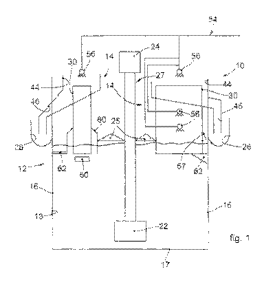
- Fig. 1 is a schematic sectional front view of an apparatus for foam
separation in accordance with some embodiments described herein;
- Fig. 2 is a top view of an apparatus in accordance with some
embodiments described herein;
- Figs. 3a-3b are schematic views of embodiments of combinations of
modular elements in accordance with some embodiments described
8
CA 03007934 2018-06-08
WO 2017/098401
PCT/IB2016/057374
herein;
- Fig. 4 is a schematic perspective view of a foam support module in
accordance with some embodiments described herein;
- Figs. 5a-5c are schematic views of some embodiments of the foam
support module of Fig. 3;
- Fig. 6 is a schematic view of some apparatuses for foam separation in
accordance with some embodiments described herein, connected together
in series;
- Fig. 7 is a schematic sectional front view of a variant of an apparatus
for
foam separation in accordance with some embodiments described herein;
- Fig. 8 is a top view of an apparatus for foam separation in accordance
with the variant of Fig. 7;
- Fig. 9 is a schematic sectional front view of a further variant of an
apparatus for foam separation in accordance with some embodiments
described herein.
For a better understanding, the same reference numerals have been used
in the drawings, wherever possible, to identify identical common
elements. It goes without further saying that elements and features of one
embodiment can be conveniently incorporated into other embodiments as
well.
DESCRIPTION OF SOME EMBODIMENTS
Reference will now be made in detail to various embodiments of the
invention, one or more examples of which are illustrated in the annexed
drawings. Each example is provided in order to illustrate the invention
and should not be understood as a limitation thereof. For instance, the
9
CA 03007934 2018-06-08
WO 2017/098401
PCT/IB2016/057374
features of an embodiment illustrated or described herein can be adopted
in or associated with other embodiments in order to produce a further
embodiment. It is understood that the present invention includes all such
modifications and variations.
In accordance with the present invention, an apparatus 10 for foam
separation can be used for separating hydrophobic substances in general,
e.g. for mineral treatment purposes, in particular for coal treatment, or for
environmental, recycling and water treatment applications, in order to
obtain separation between solids and/or between solid and liquid and/or
between liquids.
In the embodiments according to the present description, the expression
"foam separation" refers to a chemical process falling within the category
of those techniques referred to in the industry as "adsorptive bubble
separation". In particular, two examples of "foam separation" processes
are the "froth flotation" process and the "foam fractionation" process.
The apparatus 10 according to the present invention comprises a foam
separation cell 12, 112, 212 and at least one modular foam support
element 30 which is movably and/or removably associated, also during
the process, with the foam separation cell 12, 112, 212.
In some embodiments, a plurality of modular elements 30 are included,
which are mutually associated to define a three-dimensional foam support
structure.
The modular elements 30 may have an elongated, flat or curved shape,
and may be mutually aligned, concentric or oblique to form a grid, or a
toroidal or circular-crown shape, or any possible three-dimensional
CA 03007934 2018-06-08
WO 2017/098401
PCT/IB2016/057374
structure 28 that can be obtained by combining and intersecting modular
elements 30, so as to allow the foams to flow upwards.
The support structure 28 may have foam containment and support
volumes providing large additional support surfaces for the bubbles, so
that they will not be supported by the underlying bubbles only and can
thus form more stable and taller, or deeper, foams.
In some embodiments, the modular elements 30 combined together to
form the structure 28 can form the internal structure of a foam support
module 14.
In embodiments described herein with reference to Fig. 1, a mechanical
foam separation cell 12 comprises a treatment chamber 13, defined by
outer side walls 16 and by a bottom wall 17, and configured to contain
the pulp or liquid and to carry out the separation of the hydrophilic
material from the hydrophobic material. The foam separation cell 12
comprises an opening 18 for supplying a flow of material to be separated,
and an drain opening 20 for draining the effluent, i.e. the liquid
containing the hydrophilic material, which is generally located near the
bottom 17.
The foam separation cell 12 also includes a rotor 22 connected to and
driven by a motor 24, which keeps the pulp in agitation and prevents
sedimentation of the material contained therein. There may also be air
supply means 27, e.g. associated with the rotation of the motor or
connected to a blower or a compressor; this air is necessary for
generating the bubbles to which the hydrophobic material will adhere.
For example, the combined action of the rotor and stator of the impeller
11
CA 03007934 2018-06-08
WO 2017/098401
PCT/IB2016/057374
22 may be used (the stator is not shown in the drawing) in order to
generate small bubbles.
The mechanical separation cell 12 is also generally provided with a
support structure, also referred to as bridge, 25, configured to support the
assembly including the impeller 22 and the motor 24. The bridge 25 may
be a frame or a support plate.
The bubbles rise towards the upper part of the foam separation cell 12
and, when they have reached a height taller than the outer walls 16, will
tend to fall into suitable foam collectors 26, from which they will be
discharged in order to recover the separated material concentrate.
In addition and/or as an alternative, near the edge of the side wall(s) 16 of
the separation cell 12 there may be one or more ports (not shown in the
drawings) for draining or letting out the foam from the cell 12 into the
collectors 26.
In some embodiments, the modular elements 30 and/or the foam support
modules 14 are installed in the upper part of the foam separation cells 12,
and can be partly placed inside the pulp or on top of it. The modular
elements 30 and/or the modules 14 may be applied to the edge of a foam
separation cell 12 or associated therewith, or suspended with respect to
the pulp or liquid, or floating thereon.
Advantageously, the modular elements 30 and/or the foam support
modules 14 are associated with the separation cell 12 in a movable and/or
removable manner. Because of this, they can be moved or removed also
while the cell 12 is in operation during the foam separation process of the
invention.
12
CA 03007934 2018-06-08
WO 2017/098401
PCT/IB2016/057374
This will make it possible to take action immediately as required: for
example, in the event of a malfunction, a failure or the like, or for
replacing one or more modular elements 30 or foam support modules 14,
or for checking the progress of the separation process, or for taking foam
samples to be examined.
As a matter of fact, when removing, raising or anyway moving one or
more modular elements 30 and/or foam support modules 14, also the
foam deposited thereon will be removed.
The foam thus obtained can then be analyzed separately in a laboratory or
visually by an operator for the purpose of evaluating its properties (e.g.
density, purity, composition, etc.) and obtaining an indication about the
progress of the separation process; it will thus be possible to check
whether the process is going on regularly or requires some changes in the
process parameters (e.g. quantity of blown air, revolution speed of the
impeller 22 for pulp agitation, time of permanence in the separator, etc.).
In some embodiments, the foam support module 14 can be hermetically
or non-hermetically connected to a foam separation cell 12, 112, 212; in
both cases, the foams will rise due to the wall effect increased by the
inner structure 28.
In accordance with embodiments described herein with reference to Figs.
1 and 2, the modular elements 30 and/or the foam support modules 14
can be associated with the foam separation cell 12 in such a way as to
cover the whole free surface of the pulp, or only a part thereof.
For example, in the right-hand part of Figs. 1 and 2 an exemplary
solution is shown wherein six modular elements 30 and/or foam support
13
CA 03007934 2018-06-08
WO 2017/098401
PCT/IB2016/057374
modules 14 cover the entire free surface of the pulp (from the center
towards the wall 16) and collect all the foam and the concentrate that rise
towards the upper part of the foam separation cell 12; in this case, the
covering is almost hermetical.
In the left-hand part of Figs. 1 and 2 an exemplary solution is shown
wherein four foam support modules 14 are so arranged as to not cover the
whole free surface, but only the innermost part that is farthest from the
foam collector 26. The foams can thus be discharged in the traditional
manner, with particles and fibers, including rough ones, being collected
in the foam collectors 26, while the innermost part is cleaned in the foam
support module 14 to provide a purer concentrate. These two solutions
may be used either alone or combined together or with further
embodiments.
The solution illustrated in the left-hand part allows using the foam
support module 14 as a "foam crowder" in traditional foam separation
cells 12, 112, 212, so that deeper foams can be formed also near the outer
walls 16.
The foams must not be too deep in the outermost part because this would
shorten the average time of permanence in the foam separation cells 12,
112, 212, since the usable volume would be reduced, leading to reduced
recovery of hydrophobic material in the foams. The modular elements 30
and/or the foam support modules 14 offer the advantage that very tall
foams can be obtained while keeping unchanged the average time of
permanence of the pulp or liquid in the foam separation cell 12, 112, 212.
The average time may also be increased, if the level of the pulp or liquid
14
CA 03007934 2018-06-08
WO 2017/098401
PCT/IB2016/057374
is raised and the respective modular elements 30 and/or foam support
modules 14 are so arranged as to hermetically cover the whole free
surface. This may turn out to be particularly useful in existing systems of
foam separation cells 12, 112, 212, which cannot provide satisfactory
results because they are undersized.
According to embodiments described herein with reference to Fig. 3a, the
modular elements 30 can comprise modular-wall elements 30a, 30b
arranged parallel or in transverse directions to define the structure 28, e.g.
in the form of a three-dimensional grid. The modular elements 30a, 30b
may be disposed in orthogonal directions or inclined relative to one
another by an angle other than 90 .
The modular elements 30a, 30b may be either aligned vertically or
arranged obliquely.
In some embodiments, the modular elements 30 may have flat surfaces or
be provided with through holes or slots to allow the bubbles and the
foams to flow in the transverse direction.
The modular elements 30a, 30b define foam passage volumes having a
relatively narrow cross-section. Such sections may become clogged with
solid particles or fibers contained in the pulp.
The presence of perforated modular elements 30a, 30b will allow pulp,
foam and/or bubbles to flow transversally to ensure self-levelling of the
pulp or liquid inside the structure 28. This means that lateral movements
and higher efficiency can be obtained when a channel or passage gets
clogged, by allowing its content to re-distribute itself into the adjacent
passages.
CA 03007934 2018-06-08
WO 2017/098401
PCT/IB2016/057374
According to a variant embodiment described herein with reference to
Fig. 3b, the structure 28 may comprise modular elements 30a arranged
parallel to one another with the interposition of linking modular elements
30c having an elongated shape and a thickness that is much smaller than
the dimensions that define its surface. In some embodiments, the linking
modular elements 30c may be arranged in the orthogonal direction or
inclined by an angle a other than 900 with respect to the modular
elements 30a.
A bubble and/or a particle moving in the vertical direction has a weight
that is equal to its mass multiplied by gravitational acceleration (m x g).
The inclined linking element 30c can provide the bubbles with support
equal to mxgx cosa in the direction perpendicular to the surface of the
linking element 30c; the particle will then have a reduced weight in the
direction parallel to the surface, equal to mxgx sina, i.e. less than or
equal to m x g. The weight of the bubbles and of the particles contained
therein will thus be reduced not only by the wall effect caused by the
modular elements 30a, but also by the reaction exerted by the inclined
linking element 30c.
In further embodiments, the structure 28 may consist of a lattice made up
of a plurality of solid or hollow modular elements 30 having one
prevalent dimension.
In some possible solutions, the modular wall elements 30a, 30b may be
made as one piece extending from the lower part to the upper part of the
internal structure 28 or along a transverse development thereof, or they
may be made up of multiple modular elements 30, mutually
16
CA 03007934 2018-06-08
WO 2017/098401
PCT/IB2016/057374
superimposed and combined, or connected and kept spaced apart by
means of further linking elements 30c, e.g. linking tie rods.
Fig. 4 is used herein as a reference to describe a foam support module 14
that comprises at least one modular element 30, in particular a plurality
thereof
The foam support module 14 may have peripheral surfaces and inner
surfaces, defined by the modular elements 30 that provide additional
support surfaces for the foams.
In some embodiments, the foam support module 14 may comprise side
walls 36 that define an enclosure 38 which peripherally encloses the
modular elements 30. The side walls 36 may be also configured to allow
the foam support module 14 to be associated with the upper part of a
foam separation cell 12.
The enclosure 38 may be defined by a lower edge 37 and an upper edge
39. The lower edge 37 may be immersed in the pulp or liquid, or be
suspended over it, while the upper edge 39 may be immersed or protrude
past the outer walls 16 of the treatment chamber 13.
When the foam support module 14 is partly inserted in the treatment
chamber 13, the side walls 36 may have through holes or slots in at least
their lower part on a level with the liquid to allow lateral movement
thereof inside and outside the foam support module 14. In the part
external to the liquid, the side walls 36 may be designed as solid walls to
retain the foams and support them until they reach the upper edge 39,
where they will then be removed.
In some embodiments, the side walls 36 may be made as one piece, or
17
CA 03007934 2018-06-08
WO 2017/098401
PCT/IB2016/057374
they may be made up of segments joined and combined together to form
the enclosure 38.
In some embodiments, the enclosure 38 may have a constant or variable
cross-section between the lower edge 37 and the upper edge 39. The
cross-section may also vary more than once.
For example, the cross-section defined by the lower edge 37 of the foam
support module 14 may have dimensions Al and Bl, whereas the section
defined by the upper edge 39 may have dimensions A2 and B2
respectively equal to the dimensions Al and Bl. The dimensions A2 and
B2 of the upper edge 39 can be selected as a function of the vertical
velocity of the foams to be obtained. If the air flow rate through the
section remains constant, the mean velocity will be inversely proportional
to the area of the section.
In some embodiments, the modular elements 30 may be anchored and
fixed to the side walls 36 by using suitable known fastening means. Some
examples of fastening means may be welds, bolts, hooks, joints, flanges,
or the like.
Preferably, said fastening means allow the modular elements 30 and/or
the foam support modules 14 to be removed even during the separation
process, i.e. while the separation cell 12 is in operation.
One variant embodiment may utilize a support element 40 configured to
support the modular elements 30 in the desired position and fasten them
to the side walls 36. The support element 40 may be located at the lower
edge 37 or at a predefined distance hl from the lower edge 37.
One variant embodiment may include an end-of-travel element 42
18
CA 03007934 2018-06-08
WO 2017/098401
PCT/IB2016/057374
configured to limit the vertical movement of the modular elements 30.
The end-of-travel element 42 can be located near the upper edge 39, e.g.
at a distance h2 from the latter.
In some embodiments, the support element 40 and/or the end-of-travel
element 42 may comprise bars, grids or other elements suitable for
supporting the modular elements 30 while allowing both the liquid and
the air bubbles to pass.
In some embodiments, the support element 40 and/or the end-of-travel
element 42 may be removably secured to the side walls 36, so that the
modular elements 30 can be quickly extracted in order to carry out
cleaning and maintenance operations.
Some embodiments may include only one support element 40 and only
one end-of-travel element 42 for the entire internal structure 28, or
additional support elements 40 and/or limiting elements 42 may be
arranged in intermediate positions between some modular elements 30.
In some embodiments, the foam support modules 14 may comprise
bubble generation and/or distribution devices 50 configured to introduce
additional bubbles in order to make the separation process more efficient.
Bubbles will thus be introduced both into the foam separation cells 12,
112, 212, via the known generators 21, 27, and into every single foam
support module 14. In this manner, a larger number of bubbles can be
supplied and forced into the foam support module 14 in order to regulate
the separation and recovery of the hydrophobic material.
Additional bubbles may also be generated via forced recirculation of a
part of the material exiting the foam separation cells 12, 112, 212 into
19
CA 03007934 2018-06-08
WO 2017/098401
PCT/IB2016/057374
further foam separation cells 12, 112, 212. This solution is typical of
bubble generators comprising Venturi devices or "in-line mixers".
In some embodiments, the foam support module 14 may comprise a foam
recirculation circuit 52 configured to allow recirculation of the foams
collected from upstream and/or downstream foam separation cells 12,
and to output the foams at different heights of the foam support module
14.
The foam support module 14 may also comprise a foam washing circuit
54 of its own, configured to wash the foams supported by the modular
elements 30 in order to improve the purity thereof, i.e. in order to obtain a
purer concentrate of separated material.
The foam washing circuit 54 may comprise one or more washing devices
56 configured to dispense water, or another suitable liquid, into the foam
support modules 14, e.g. at different heights. The washing devices 56 can
be used in addition to existing washing devices, like those included in
column-type foam separation cells 112 (Fig. 7).
In some embodiments described herein with reference to Fig. 4, the foam
support modules 14 may be equipped with handles 58, eyelets or other
elements configured to allow for easy handling and installation of the
foam support modules 14.
In some embodiments described herein with reference to Fig. 4, the foam
support modules 14 may comprise support elements 60 configured to
connect the foam support modules 14 to the foam separation cells 12,
112, 212, e.g. at and/or near the ends of the outer walls 16 of the foam
separation cells 12, 112, 212, and/or suspended over the pulp or liquid.
CA 03007934 2018-06-08
WO 2017/098401
PCT/IB2016/057374
The support elements 60 may also be configured to connect together two
or more foam support modules 14.
The support elements 60 may comprise lateral or angular protrusions,
joints, hooks and removable fastening elements, and can be positioned at
any height of the foam support module 14 for inserting it into and/or
associating it with a foam separation cell 12, 112, 212 and/or a further
foam support module 14, and/or the support bridge 25, and for holding it
in the desired position.
The support elements 60 may be directly connected to the walls 16 or to
the bridge 25, or they may be associated with and/or connected to
suitable support structures 62 fastened inside the treatment chamber 13 of
the foam separation cells 12, 112, 212. The support structures 62 may be
configured to support the single modular elements 30 and/or the foam
support modules 14.
In some variant embodiments, the modular elements 30 and/or the foam
support module 14 can be constrained to the foam separation cell 12, 112,
212, so that they can move freely in the vertical direction, e.g. through
the use of floats. With this solution, the height of the foams can be kept
constant in the structure 28 independently of the level of the liquid in the
foam separation cell 12, 112, 212. There may be end-of-travel elements
configured to limit the downward movement and to prevent the modular
elements 30 and/or the foam support module 14 from damaging parts of
the foam separation cell 12, 112, 212, e.g. the impeller, or anti-wear
coatings.
In some embodiments that may be combined with all of the embodiments
21
CA 03007934 2018-06-08
WO 2017/098401
PCT/IB2016/057374
described herein, the foam support modules can be equipped, on one or
more side walls 36 of the enclosure 38, with side doors 57 configured to
allow the concentrate to be removed from the foam support module 14,
should the latter become clogged and prevent the foams and the
concentrate from correctly travelling towards the upper edge 39. It will
thus be possible, in the event that a foam support module 14 becomes
obstructed, to continue using the separation apparatus 10 as a traditional
foam separation cell 12, 112, 212.
Figs. 5a-5c are useful to describe different methods for collecting the
foams at the upper edge 39 of the foam support module 14.
The foams can be collected, e.g. by overflow, into suitable collectors 44,
which are then evacuated via a collection tube 46 (Fig. 5a) or through a
drain opening from the collector 44 into an underlying container,
collector or tank (Fig. 5b).
In some possible variants, the foams can be collected and discharged
directly through one or more collection tubes 48 arranged on top of the
foam support modules 14 (Fig. Sc).
The collection tubes 46 and/or 48 can be connected to respective foam
collectors 26 of the foam separation cells 12, 112, 212.
Fig. 6 is useful to describe an exemplary embodiment of a bank 100
comprising a plurality of separation apparatuses 10, each one comprising
a foam separation cell 12, e.g. a mechanical one (some parts of which,
e.g. the impeller, are not shown for clarity), and a foam support module
14, connected together to allow the pulp and the hydrophobic material to
flow between them.
22
CA 03007934 2018-06-08
WO 2017/098401
PCT/IB2016/057374
It has been experimentally demonstrated that the efficiency of the process
increases when the hydrophobic material recovered from a bank of foam
separation cells 12, 112, 212 is fed directly into the foams of the
preceding foam separation cells 12, 112, 212 in order to recirculate the
concentrate collected therein.
The technical problem encountered in prior-art industrial plants lies in the
fact that it is impossible to attain a foam depth that will allow
recirculating the collected concentrate directly into the foams, let alone
subsequently rejecting the hydrophilic material still present therein.
The foam support module 14 allows the formation of deep foams through
the wall effect and then feeding the hydrophobic material directly into the
foams as shown in Fig. 6, which shows by way of example how the
concentrate is recirculated directly from one foam support module 14 into
another between a foam separation cell 12 and the preceding one via a
foam recirculation circuit 52.
For example, the pulp is supplied into the first foam separation cell 12 on
the left (arrow IN), wherein a first separation occurs between foams and
pulp; the foams retaining the hydrophobic material will then go up, while
the pulp containing the hydrophilic material will be delivered into the
next foam separation cell 12 (arrow D) to be subjected to further
separation processes. Finally, when the last foam separation cell 12 of a
series or bank of the system 100 is reached, the effluent containing
almost exclusively hydrophilic material will be definitively evacuated
(arrow OUT1).
Instead, the foams containing the separated hydrophobic material will
23
CA 03007934 2018-06-08
WO 2017/098401
PCT/IB2016/057374
follow an inverse path, since they will be recovered from the top of the
last foam separation cell 12 through the collection tube 48 and
recirculated into the foams collected in the foam support module 14 of
the preceding foam separation cell via the foam recirculation circuit 52,
and so on until they return into the foam support module 14 of the first
foam separation cell 12, from which the separated concentrate will be
recovered (arrow OUT2).
Total, or preferably partial, recirculation of the material floated in the
foam support modules 14 may also be effected differently by using a
pump or an "air lift". Also, it can be chosen whether to recirculate only
the concentrate collected in the modules 14 or the entire amount of
(floated) foams produced.
It is clear that this type of supply can also occur between different banks
100, not necessarily between foam separation cells 12 of the same bank
100.
The foam separation cells 12, 112, 212 are typically connected in banks
100 in a foam separation plant, and can act as foam separation cells 12,
112, 212 of a "rougher", "scavenger" or "cleaner" bank. For example,
they may be configured to carry out a first rough separation between
hydrophilic and hydrophobic materials, or subsequent separation steps for
recovering additional hydrophobic material from the effluent, and/or for
eliminating any hydrophilic material that may still be present in the
concentrate obtained from the preceding foam separation cells 12, 112,
212.
.. In some variant embodiments described herein with reference to Fig. 7,
24
CA 03007934 2018-06-08
WO 2017/098401
PCT/IB2016/057374
an apparatus 10 comprises a column-type foam separation cell 112
comprising a treatment chamber 13 defined by outer walls 16 and a
bottom wall 17, and configured to retain the pulp and carry out the
separation of the hydrophilic material from the hydrophobic material.
The column-type foam separation cell 112 comprises an intake opening
18 for taking in the pulp or liquid and a drain opening 20 for draining the
effluent.
Generally, the column-type foam separation cell 112 comprises also an
air bubble generator 21, configured to generate bubbles of the desired
size inside the treatment chamber 13.
Column-type foam separation cells 112 further comprise washing devices
23 that deliver water in countercurrent against the foams to promote the
sliding of any hydrophilic material retained by the air bubbles towards the
bottom 17.
In some embodiments described herein with reference to Fig. 7, the foam
support modules 14 can be so arranged as to cover, whether totally or
partially, the top surface of the foam separation cell 112. The foam
support modules 14 may be either inserted into the treatment chamber 13
(on the left in Fig. 7) or secured to the upper part of the outer walls 16
.. (on the right in Fig. 7), so that they will still be in fluidic connection
with
the treatment chamber 13. Between adjacent foam support modules 14,
foam passage channels 64 may be provided to convey the foams towards
the collectors 44 and/or towards additional collectors.
When the foam support modules 14 protrude upwards from the treatment
chamber 13, the total volume of the apparatus 10 will be increased, thus
CA 03007934 2018-06-08
WO 2017/098401
PCT/IB2016/057374
improving the performance thereof
By way of example, assuming that 3m of foams need to be generated in a
column-type foam separation cell 112 that is 6.5m tall, which generally
works with foams approx. 0.5m tall, the usable volume of liquid in the
foam separation cell 112 will be reduced to just 3m, i.e. halved. If the
foam support module 14 protrudes from the foam separation cell 112,
2.5m of foams can be generated outside the foam separation cell 112
while keeping constant the average time of permanence of the pulp or
liquid, thereby providing foams six times taller.
Production of deeper foams is also promoted when the foam support
modules 14 are immersed underneath the foams. Moreover, the modules
14 can dampen turbulences and "waves" that may be generated if too
much air is blown. Thanks to wave dampening, the modules 14 allow
operation with very shallow foams, because no pulp or liquid will be
discharged directly into the concentrate.
Fig. 8 is useful to describe a schematic top view of an apparatus 10 for
particle separation that comprises a column-type foam separation cell
112, the surface of which is almost entirely covered with a plurality of
foam support modules 14, the cross-section of which is in this case a
circular crown sector. According to this solution, the foam support
modules 14 have a circular-sector cross-section and are disposed in
connection with one another to form circular crowns.
In some variant embodiments described herein with reference to Fig. 9,
an apparatus 10 comprises a centrifugal foam separation cell 212
comprising a treatment chamber 13 defined by outer side walls 16 and
26
CA 03007934 2018-06-08
WO 2017/098401
PCT/IB2016/057374
top walls 19, and configured to separate the hydrophilic material from the
hydrophobic material. The pulp or liquid is supplied through the opening
18, and the effluent is drained through the drain opening 20. The
treatment chamber 13 may have a cylindrical shape in its upper part and a
truncated conical shape tapering in its lower part towards the drain
opening 20.
The bubbles will rise towards the upper part of the foam separation cell
212 and, when they reach a certain height inside the treatment chamber
13, they will tend to fall back down into suitable foam collectors 26
arranged inside the treatment chamber 13.
In this solution, one or more modular elements 30 and/or foam support
modules 14 can be secured to a top wall 19 of the foam separation cell
212, e.g. by connecting the support element 40 to a support structure 62.
A closing element 66, configured to close the mouth of the foam
collector 26, may also be connected to the support structure 62 and/or to
the support element 40 in order to force all the bubbles to go up towards
the foam support module 14.
The closing element 66 can be configured to switch from a mouth closing
position to a mouth opening position and, in the closing position, it may
.. rest on abutment elements 68 that are present in the foam collector 26.
In light of the above description, it is possible to understand that the
peculiarity of the invention of using one or more modular elements 30
and/or foam support modules 14 that are movable and/or removable
during the foam separation process allows them to be extracted from the
separation cell 12, 112, 212 also when the latter is in operation.
27
CA 03007934 2018-06-08
WO 2017/098401
PCT/IB2016/057374
On the one hand, this allows the execution of maintenance, cleaning and
replacement work on the modular elements 30 or modules 14; on the
other hand, it also allows taking samples of the foam deposited on such
modules.
In fact, the foam retained by the modular elements 30 or by the modules
14 can be picked up when they have been raised (by floats or by an
operator) or removed from the cell 12, 112, 212; such foam can then be
analyzed (e.g. in a laboratory or visually by an operator) to obtain useful
information about its composition, purity, etc., which information will
allow monitoring the progress of the separation process and making any
necessary changes, should any differences be detected with respect to the
desired conditions.
In this respect, it must be pointed out that it is important for the invention
that the modular elements 30 and/or the foam support modules 14 are
accessible from outside the separation cell 12, 112, 212; preferably, they
can be manipulated from above by an operator or by a lifting device
(crane, travelling crane, or the like): it is for this reason that the
separation cell 12 is preferably open at the top.
It is clear that the apparatus and the process for particle separation
described herein may be subject to changes and/or additions of parts
without departing from the scope of the present invention.
It is also clear that, although the present invention has been described
herein with reference to some specific examples, a man skilled in the art
will certainly conceive many other equivalent embodiments of an
apparatus and a process for particle separation having the features set out
28
CA 03007934 2018-06-08
WO 2017/098401
PCT/IB2016/057374
in the claims, and hence still falling within the protection scope defined
therein.
10
INDEX
10 Apparatus for foam separation
12 Mechanical foam separation cell
13 Treatment chamber
14 Foam support module
16 Outer walls
17 Bottom wall
18 Supply opening
19 Upper outer walls
29
CA 03007934 2018-06-08
WO 2017/098401
PCT/IB2016/057374
20 Drain opening
21 Air bubble generator
22 Impeller
23 Washing devices
24 Motor
25 Bridge
26 Foam collectors
27 Air introduction means
28 Internal structure
30 Modular elements
30a Modular walls
30b Modular walls
30c Linking modular elements
36 Side walls
37 Lower edge
38 Enclosure
39 Upper edge
40 Support element
42 End-of-travel element
44 Collectors
46 Collection tube
48 Tubes
50 Bubble generators
52 Foam recirculation circuit
54 Foam washing circuit
CA 03007934 2018-06-08
WO 2017/098401
PCT/IB2016/057374
56 Washing device
57 Doors
58 Handles
60 Support elements
62 Support structures
64 Foam passage channels
112 Column-type foam separation cell
212 Centrifugal foam separation cell
Al Dimension
A2 Dimension
B1 Dimension
B2 Dimension
D Arrow
hl Distance
h2 Distance
a Angle
IN Pulp inlet
OUT1 Effluent outlet
OUT2 Concentrate outlet
31