Note: Descriptions are shown in the official language in which they were submitted.
CA 03008134 2018-06-11
WO 2017/109561
PCT/IB2016/001785
1
A method of a heat transfer of a non-metallic or metallic item
The present invention relates to a method of heat transfer of non-metallic or
metallic item. In particular, it is well suited for steel, aluminum, stainless
steel,
copper, iron, copper alloys, titanium, cobalt, metal composite, nickel
Industries or
non-metallic industries such as plastics.
With a view of saving energy consumption, it is possible to improve the
performance of heat exchangers systems and to introduce various heat transfer
enhancement techniques. Some techniques have focused on electric or magnetic
field application. Although an improvement in energy efficiency is possible
from
such points of view, an improvement can also be realized concerning the heat
transfer fluid. Usually, fluids such as water, engine oil, ethylene glycol,
etc. are
used as heat transfer fluid. However, they have poor heat transfer performance
and therefore high compactness and effectiveness of heat transfer systems are
necessary to achieve required heat transfer. Among the efforts for enhancement
of
heat transfer, the application of additives to liquids is more noticeable.
For example, a surfactant such as LEVENOL C-421 which is
polyoxyethylene mono- and di- glycerides, can be added into water for
improving
the heat transfer coefficient or at least the thermal conductivity. However,
although
the conductivity enhances in some cases, the presence of the surfactant
results in
the formation of foam. The presence of foam is a huge problem since it is
really
difficult to remove it, in particular in industrial scale. Moreover, the
presence of a
surfactant increases the corrosion of the heat transfer system, specially the
pipe
wherein the heat transfer fluid flows. Finally, scale can be formed
particularly in the
heat transfer system.
In steel making industry, for example the patent application US2003062147
discloses a method for manufacturing electrical steels. After the continuous
casting, for producing grain oriented electrical steel from a cast strip, a
rapid
secondary cooling of the cast strip is realized to control the precipitation
of the
grain growth inhibiting phases.
Specifically, it describes a method for producing grain oriented electrical
steel strip comprising the steps of:
CA 03008134 2018-06-11
WO 2017/109561
PCT/1B2016/001785
2
(a) forming a continuously cast electrical steel strip having a thickness of
no
greater than about 10 mm,(b) slow cooling with air at a rate of about 15
C/second
said strip to a temperature of from about 1150 to about 1250 C. such that it
becomes solidified and
(c) subsequently performing a rapid secondary cooling on said steel strip
wherein
the strip is cooled at a rate of from about 65 to about 150 C/second to a
temperature of no greater than about 950 C.
The cooling process can be accomplished by the direct application of
cooling sprays, directed cooling air/water mist, or impingement cooling of the
cast
strip onto solid media such as a metal belt or sheet.
However, with such cooling processes, it is possible not to reach the
desired fast cooling. Indeed, the directed cooling air/water mist is a cooling
difficult
to control in industrial scale. Moreover, both cooling process are too long
because
the heat transfer flow between the cast strip and the cooling fluid or cooling
solid is
too low.
Another example is disclosed in a scientist publication called "Effect of
Cooling Patterns on Microstructure and Mechanical Properties of Hot-Rolled Nb
Microalloyed Multiphase Steel Plates" (Dong-sheng ZHENG, Fu-xian ZHU, Yan-
mei LI, Bing-zhang CHEN, Journal of Iron and Steel Research, International,
Volume 18, Issue 8, August 2011, Pages 46-52). It describes the effect of the
run-
out table cooling patterns on the microstructure and mechanical properties of
Nb
microalloyed steel plates which was investigated by hot rolling experiment.
The
results showed that the mixed microstructure containing ferrite, bainite and
significant amounts of retained austenite can be obtained through three kinds
of
cooling patterns on the run-out table under the same hot rolling condition.
For
example, during the cooling process in a hot rolling process, the run-out
table can
cool the steel strip by the following steps:
(a') cooling from 820 C to 700 C at an intermediate cooling rate, the water
used as
coolant being in laminar regime flow,
(b') cooling from 700 C to 640 C at a slow cooling rate, the air is used as
coolant
and
(c') cooling from 640 C to 440-460 C at a ultra-fast cooling rate, the water
being
used as coolant.
3
However, in order to reach the desired cooling rate, a huge amount of water is
needed for performing steps (a') and (c'). Additionally, there is a risk that
the cooling
steps using water take too much time in industrial scale. Indeed, the heat
transfer
coefficient of water is not high enough to quickly obtain an intermediate or
ultra-fast
cooling rate. Thus, a heat transfer fluid having high heat transfer
coefficient is needed.
Recent investigations in nanotechnology have allowed the development of a
new category of heat transfer fluid comprising nanoparticles. Such fluids also
called
"Nanofluid" are liquid suspension containing particles having at least one
dimension
below 100nm. These heat transfer fluids have usually an increased heat
transfer
coefficient. These fluids are usually used as cooling fluid.
Such fluids can be used for accelerating the heat transfer, for example the
cooling, between a non-metallic or metallic and a heat transfer fluid. For
example, in
steel making industry, during the cooling process in a hot rolling process,
the run-out
table cools the steel strip from approximately 800-950 C at the entrance to
450-600 C at the exit. Thus, for some steel grades, a heat transfer fluid
having high
heat transfer coefficient is needed.
However, sometimes, the cooling is performed in two or more steps, the
cooling rate of each steps being fast but not equivalent. Thus, such method
comprising several cooling steps is needed.
The purpose of the invention is to provide an easy to implement method of heat
treatment of a non-metallic or metallic item comprising at least two heat
transfers
between the item and the heat transfer fluids having heat transfer
coefficients above
the heat transfer coefficient of water. In particular, there is a need to
provide a method
wherein the heat transfer can be fast and controlled.
The present invention also relates to a method of heat treatment of a non-
metallic or metallic item comprising:
A. at least one step A) of heat transfer between said item and a heat
transfer fluid A' comprising a fluid medium and nanoparticles, the heat
transfer fluid having a heat transfer coefficient above the heat transfer
coefficient of water and
CA 3008134 2019-12-12
3a
B. at least one step B) of heat transfer between the item and a heat
transfer fluid B' comprising a fluid medium and nanoparticles, the heat
transfer fluid B' having a heat transfer coefficient different from the heat
transfer coefficient of A' and above the heat transfer coefficient of water
said heat transfer fluids A' and B' being different.
The following terms are defined:
- heat transfer fluid comprising nanoparticles (so-called Nanofluid) means
a liquid
suspension containing particles having at least one dimension below 100nm,
- laminar flow means a flow with a Reynolds number below a critical value
of
approximately 2300,
CA 3008134 2019-12-12
CA 03008134 2018-06-11
WO 2017/109561
PCT/IB2016/001785
4
- turbulent flow means a flow with a Reynolds number larger than a critical
value of
about 4000,
- Percolation threshold concentration is the concentration of nanoparticles
above
which they are connected forming a long-range network. For heat transfer
applications, it is suitable that such network connects the hottest part, i.e.
the part
where the heat starts to flow, of the fluid and the coldest part of the fluid,
i.e. the
one where the heat is evacuated. In other words, below the Percolation
threshold
concentration, nanoparticles are not connected. When the Percolation threshold
concentration is obtained, the network formed with nanoparticles, having
higher
thermal conductivity than the fluid medium, allows the heat carriers to take a
path
with much less thermal resistance, thus enhancing the thermal conductivity of
the
fluid, and therefore the heat transfer coefficient
- wt.% means percentage by weight,
- Graphite nanoplatelets means a multilayered system of graphene sheets
having
a thickness around between 5 and 20nm,
- Few layers graphene means a ,multilayered system of graphene sheets
having a
thickness between 1 and 5 nm and
- Graphene means a single-atom-thick sheet of hexagonally arranged, bonded
carbon atoms, presenting usually a thickness below mm.
Other characteristics and advantages of the invention will become apparent
from the following detailed description of the invention.
To illustrate the invention, various embodiments and trials of non-limiting
examples will be described, particularly with reference to the following
Figures:
Figure 1 illustrates an example of one nanoplatelet according to the present
invention.
Figure 2 illustrates an example of multilayered nanoplatelets according to
the present invention.
Figure 3 illustrates an example of spherical nanoparticle according to the
present invention.
Figure 4 illustrates an example of elliptical nanoparticle according to the
present invention.
The invention relates to a method of heat treatment of a non-metallic or
metallic item comprising:
CO. 03008134 2018-06-11
WO 2017/109561
PCT/IB2016/001785
A. at least one step A) of heat transfer between said item and a heat
transfer fluid A' comprising a fluid medium and nanoparticles, the heat
transfer
fluid having a heat transfer coefficient above the heat transfer coefficient
of water
and
B. at least one step B) of heat transfer between the item and a heat
transfer fluid B' comprising a fluid medium and nanoparticles, the heat
transfer
fluid B' having a heat transfer coefficient different from the heat transfer
coefficient
of A' and above the heat transfer coefficient of water
said heat transfer fluids A' and B' being different.
More preferably, the method also comprises at least one step C) of heat
transfer between the item and a heat transfer fluid C' comprising a fluid
medium
and nanoparticles, the heat transfer fluid C' having a heat transfer
coefficient
below the heat transfer coefficient of water.
Advantageously, the method also comprises at least one step D) of heat
transfer between the item and a heat transfer fluid D' comprising a fluid
medium
and nanoparticles, the heat transfer fluid D' having a heat transfer
coefficient
different from the heat transfer coefficient of C' and below the heat transfer
coefficient of water.
According to the invention, the steps A), B), C), D) can be performed in any
order, steps C and D being optional. In a preferred embodiment, the method of
heat treatment according to the invention comprises steps A) and B) performed
successively. In another preferred embodiment, step B) is performed before
step
A). Advantageously, the method of heat treatment according to the invention
comprises steps A), B) and C) performed successively. They can also be
performed in the following orders: B), C) and A) or C), A) and B). Preferably,
the
method of heat treatment according to the invention comprises steps A), B), C)
and D) performed successively. They can also be performed in the following
orders: B), C), A) and D) or A), C), D) and B).
In a preferred embodiment, the heat transfer fluid comprises nanoparticles
chosen from graphite nanoplatelets, graphene, few layers graphene, TiO2, Zn02,
ZnO, Boron- nitride, copper, silica, montmorillonite, zeolite clipnoptilolite,
vvollastonite, mica, zeolite 4A, A1203, silicate, pumice, calcium oxide or
carbon
nanotubes. Preferably, the nanoparticles do not comprise carbon nanotubes.
CA 03008134 2018-06-11
WO 2017/109561
PCT/IB2016/001785
6
For example, the nanoparticle can be spherical, elliptical or nanoplatelets.
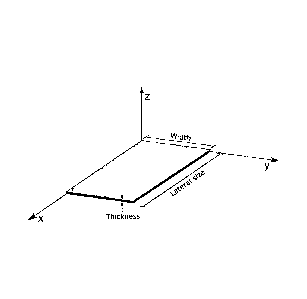
Figure 1 illustrates an example of one nanoplatelet that can be used in the
heat transfer fluid of the present invention. In this example, the lateral
size means
the highest length of the nanoplatelet through the X axis of and the thickness
means the height of the nanoplatelet through the Z axis. The width of the
nanoplatelet is illustrated through the Y axis.
Figure 2 illustrates an example of multilayered nanoplatelets that can be
used in the heat transfer fluid of the present invention. In this example, the
lateral
size means the highest length of the nanoplatelets through the X axis and the
thickness means the total height of all the stacked nanoplatelets through the
Z
axis. The width of the nanoplatelet is illustrated through the Y axis.
Figure 3 illustrates an example of spherical nanoparticle that can be used in
the heat transfer fluid of the present invention. In this example, the lateral
size
means the diameter of the nanoparticle and the thickness means the height of
the
nanoparticle.
Figure 4 illustrates an example of elliptical nanoparticle that can be used in
the heat transfer fluid of the present invention. In this example, the lateral
size
means highest length of the nanoparticle and the thickness means the height of
the nanoparticle.
The lateral size and the thickness of the nanoparticle can be measured by
Scanning Electron. Microscopy (SEM), Transmission Electron Microscopy (TEM)
and Atomic Forces Microscopy (AFM).
Preferably, the nanoparticles are multilayered nanoplatelets. Indeed,
without willing to be bound by any theory, it seems that to obtain
nanoplatelets
morphology, nanoparticles should have a multilayer structure with weak
interaction between layers, i.e. Van der Waals, hydrogen bond, mechanical
bond,
halogen bond, pi stacking, cation/anion-pi bonds, intercalation, salt bridges
and
polar-pi. This weak bonding together with a good thermal conductivity of the
nanoplatelets raises the possibility of improving heat transfer coefficient of
a fluid.
Advantageously, the thickness of nanoparticles is between 1 and 99.99 nm,
preferably between 5 to 50 nm and more preferably between 5 to 15 nm.
Preferably, the lateral size of the nanoparticle is between 26 and 50pm,
advantageously, between 35 and 45pm.
CA 03008134 2018-06-11
WO 2017/109561
PCT/IB2016/001785
7
Preferably, the nanoparticle concentration is between 0.01 wt.% and 12
wt.%, advantageously between 2 and 8 wt.% and more preferably between 4 and
7 wt.%.
In a preferred embodiment, the heat transfer fluid has a dispersing agent
being a non-surface active polymer, a surfactant or a mixture thereof. The
surfactant can be cationic, anionic, amphoteric or non-ionic.
For example, the dispersant agent can be polyvinnylpyrrolidone,
polysaccharides, sulphated polysaccharides, linear alkylbenzene sulfonates,
lignin
sulfonates, di-alkyl sulfosuccinates, quaternary ammonium compounds, sodium
stearate or a mixture thereof.
Preferably, the nanoparticles concentration / dispersing agent concentration
ratio in weight is between 3 and 18. More preferably, the nanoparticles
concentration / dispersing agent concentration ratio is between 4 and 15,
advantageously between 4 and 8 and preferably being between 4 and 6.
Without willing to be bound by any theory, it seems that when the above
ratio is controlled and the Percolation threshold concentration reached, the
heat
transfer fluid according to the invention allows for a higher thermal
conductivity
and therefore a higher heat transfer coefficient in laminar. Indeed, the
dispersing
agent would be able to avoid deposition and agglomeration of nanoparticles.
For
instance, if the dispersing agent is a surfactant, the nanoparticle would be
enclosed by a micelle consisting in a core of hydrophobic molecules and a
shell of
hydrophilic molecules. Such micelle structure allows dispersing nanoparticles
within the fluid. However to obtain percolation, in other words the formation
of the
long-range network formed by the nanoparticles, the degree of dispersion of
nanoparticles has to be limited.
Preferably, the heat transfer fluid comprises a fluid medium chosen from
water, ethylene glycol, ethanol, oil, methanol, silicone, propylene glycol,
alkylated
aromatics, liquid Ga, liquid In, liquid Sn, potassium formate or a mixture
thereof.
Gallium, Indium and Tin can be used as heat transfer fluid, in particular for
the
cooling of a metallic item. Indeed, the melting point of gallium is of 30 C,
the one
of indium is 157 C and the one of tin is of 232 C. For example, they can be
used
to cool down computer chips or laboratory equipments such as neutron sources.
The heat transfer fluid is preferably manufactured by the following steps:
CA 03008134 2018-06-11
WO 2017/109561
PCT/IB2016/001785
8
A. the provision of nanoparticles according to the present invention,
B. the provision of a fluid medium,
C. the adjustment of the nanoparticle concentration in order to achieve
percolation and
D. the mixing of the nanoparticles with the fluid medium.
According to the invention, the flow of the heat transfer fluid can be in a
laminar or turbulent flow regime. In a laminar flow regime, the heat transfer
coefficient is proportional to the thermal conductivity. On the contrary, in
turbulent
flow regime, the heat transfer coefficient depends on a set of thermo-physical
properties such as viscosity.
According to the invention, the heat transfer step is between a metallic or
non-metallic item and the heat transfer fluid. Preferably, the metallic item,
being for
example a metallic substrate, is made of aluminum, steel, stainless steel,
copper,
iron, copper alloys, titanium, cobalt, metal composite, nickel and the non-
metallic
is made of plastics.
In the prior art, the heat transferring using water as fluid medium can
usually be realized by one mode. The mode is called "contact water" which
means
that water is used to cool or heat an object by being in direct contact with
it.
According to a preferred embodiment of the invention, the item, being
metallic, is a metallic substrate and the heat transfer fluid is directly in
contact with
it. In this case, the heat transfer can be realized by jet impingement
cooling, pool
boiling, spray cooling or micro-channel cooling.
For example, in the steel making industry, the heat transfer by contact water
cooling can be implemented:
- in sprays chambers of continuous casters and hot rolling process such as
the
cooling process on the run-out table,
- In coke ovens for gas treatment and quenching of coke,
- during the slag quenching in blast furnaces, basic oxygen furnaces and
electric
arc furnaces.
Preferably, the method of the heat treatment according to the invention
further comprises at least one heating step. For example, the heating step is
performed at a temperature between 0 to 1200 C.
CA 03008134 2018-06-11
WO 2017/109561
PCT/IB2016/001785
9
be metnoa according to tne present invention can De usea in tne memod
for the manufacture of a multiphase steel as for instance Nb microalloyed
steel
plates during hot rolling in order to obtain a mixed microstructure containing
ferrite,
bainite and significant amounts of retained austenite. Such microstructure can
be
obtained through one cooling process on the run-out table. For example, during
the cooling process in a hot rolling process, the run-out table can cool the
steel
strip by the following successive steps:
A. one cooling step of the steel strip with a heat transfer fluid A')
comprising water and graphite nanoplatelets having a thickness/lateral size
ratio of
0.00025. The nanoparticles concentration is 5wt.%. The heat transfer
enhancement with respect to the one of water is of 203% in laminar flow
regime,
C. one cooling step with a heat transfer fluid C') comprising water as a
fluid medium and graphite nanoplatelets having a lateral size of 40 pm and a
thickness of 10 nm, i.e a thickness/lateral size ratio of 0.00025. The
concentration
of the nanoparticles is 7wt.%. The fluid further comprises 1wt.% of
polyvinnypyrolidone, the nanoparticles concentration / dispersing agent
concentration ratio being of 7. The heat transfer reduction with respect to
the one
of water is of -53% in turbulent regime flow at 25 C and
B. one cooling step with a heat transfer fluid comprising graphite
nanoplatelets having a thickness/lateral size ratio of 0.00025. The
nanoparticles
concentration is 7wt.%. The fluid further comprises 1wt.% of
polyvinylpyrolidone as
dispersing agent, the nanoparticles concentration / dispersing agent
concentration
ratio being of 7. The heat transfer enhancement with respect to the one of
water is
of 286% in laminar flow regime.
Thus, heat transfer fluid A') and B') allows for a rapid cooling, the cooling
of
step B) being ultra-fast compared with the cooling of step A). The heat
transfer
fluid C') allows for a slow cooling. Moreover, all cooling steps are well
controlled.
CA 03008134 2018-06-11
WO 2017/109561
PCT/1B2016/001785
Example:
Trials 1 to 3 were prepared by mixing nanographite multilayers having
graphite nanoplatelets having a thickness/lateral size ratio of 0.00025. In
trial 3,
polyvinnylpyrrolidone as dispersing agent was added.
Trial 4 consisted of water.
For each trial, the thermal conductivity of the samples has been measured
employing a DTC-25 thermal conductivity meter. The thermal conductivity
enhancement was calculated with respect to the conductivity of water, the
conductivity of water being of 0.67 W/mK at room temperature, i.e. 20 C.
In laminar flow, the heat transfer enhancement is similar to the
enhancement of thermal conductivity, so no calculation is needed to have the
heat
transfer enhancement in A).
In turbulent flow, the heat transfer enhancement was calculated thanks to
the following formula:
3/5 4/5
finf (tt,f) (.pmf) (Cp, 2/5 f)-2/5
n.f itn
f k b f b f Cp,b f Ifibf
With kit: Heat transfer coefficient of nanofluids (J/s-K-m2), hbf: Heat
transfer coefficient of
base fluid (J/s=K=m2), knf: Thermal conductivity of the nanofluids (J/s=K=m),
pnf: Density of
the nanofluids (kg/e), Cnnf: Heat capacity of the nanofluids (J/kg-K) and
pr,f: Viscosity of
the nanofluids (kg/s.m).
=
Nanoparticles Dispersing Heat transfer
thickness/lateral Cnanor
"rials Fluid concentration agent enhancement
Size ratio Gasp ratio
(wt. 94)) (wt. %) (A)
Water and
1* graphite 0.00025 5 203
nanoplatelets
Water and
2* graphite 0.00025 7 1 7 -53
nanoplatelets
Water and
3* graphite 0.00025 7 1 7 286
nanoplatelets
*: according to the present invention.
CA 03008134 2018-06-11
WO 2017/109561
PCT/IB2016/001785
11
The cooling performance of Trials 1 to 3 and Trial 4, consisting of water,
was calculated thanks to a modeling software. In this test, a steel slab
having a
density of 7854 kg/m3 was cooled during 13 seconds. The length was of 5 meter,
the width of 1meter and the slab thickness was of lOmm. The initial
temperature of
the slab was of 968 C.
On the one hand, the cooling of the Slab was successively performed with
Trials 1 to 3 as follows:
- a first cooling step with Trial 1 in laminar flow regime,
- a second cooling step with Trial 2 in turbulent regime flow and
- a third cooling step with Trial 3 in laminar flow regime.
On the other hand, Trial 4 was used in laminar flow.
The following table shows the cooling rate by using each Trial:
Trials Cooling rate ( C/s)
1* 36.8
2* 12.8
3* 46.9
4 21.4
*: according to the present invention
Trial 1 and 3 allow for a rapid cooling, the cooling using Trial 3 being
faster
than the cooling with Trial 1. Trial 2 allows for a slow cooling. Thus, with
the
method according to the present invention, it is possible to obtain a
multiphase
steel compared to water, i.e. Trial 4.