Note: Descriptions are shown in the official language in which they were submitted.
LEG ASSEMBLY METHODS AND SYSTEMS
BACKGROUND
This application claims priority to and the benefit of U.S. Provisional
Application No.
62/439,215, filed December 27, 2016, entitled LEG ASSEMBLY METHODS AND
SYS'ILMS.
Technical Field
This disclosure generally relates to systems and methods of attaching and/or
securing
components during assembly of a device. More specifically, the present
disclosure relates to
systems and methods of attaching and/or securing components during assembly of
a device
while maintaining the aesthetics and structural integrity thereof.
Related Technology
Advances in manufacturing and distribution have made it possible to create,
package,
and distribute high volumes of ready to assemble consumer goods. In some
instances, the
distributor or retailer assembles the consumer goods before the point of sale,
but it is also
common for ready to assemble consumer goods to be packaged with assembly
instructions,
making it possible for the consumer herself to assemble the packaged device at
home or at
another preferred location. Regardless of who assembles the device, it is
often important that
the finally assembled product functions as intended and that the assembly
process does not
significantly affect the overall structural integrity and aesthetic appearance
of the device.
Aesthetics can play a significant role in the perceived quality and
workmanship of a
consumer device. If, for example, there is a crack, scratch, or dent on the
device, some
consumers¨and even some distributors and retailers¨may assume the product is
constructed
of a low quality material or is otherwise defective, even though the crack,
scratch, or dent may
not affect the device's designed functionality or its structural integrity. On
the other hand, a
device lacking aesthetic malformations may connote a high level of workmanship
and product
quality, which may, in turn, increase consumer confidence in and satisfaction
with the product.
Unfortunately, some goods may include an aesthetically unpleasant malformation
as a
result of the post-manufacturing assembly process. Such malformations may not
actually affect
the quality or structural integrity of the device, but the device may
nonetheless suffer from a
consumer perception that it is in some way an aberrant device or that the
device's structural
integrity is somehow flawed.
Accordingly, there are a number of disadvantages with system and methods of
assembling devices that can be addressed.
- 1 -
CA 3008643 2019-08-27
BRIEF SUMMARY
Implementations of the present disclosure solve one or more of the foregoing
or other
problems in the art with systems and methods for assembling a device while
maintaining the
aesthetic appearance and structural integrity of a visible surface of the
device. In particular, in
one or more implementations a system includes a first assembly piece with an
assembly region
that comprises an opening defined by first and second connecting elements. The
system further
includes a second assembly piece, wherein a portion of the second assembly
piece is shaped to
fit within the opening of the assembly region. The system further includes a
fastening assembly
configured to span the first and second connecting elements and to secure the
first assembly
piece to the second assembly piece. Upon tightening of the fastening assembly,
the second
connecting element may deform and press a surface of the second assembly piece
against an
adjacent surface of the first connecting element such that the visible surface
of the first
connecting element retains a substantially even surface.
Systems and methods of the present disclosure can also include a system for
attaching
a leg to a grill skirt without deforming a visible surface of the grill skirt.
In particular, in one
or more implementations a system includes a grill skirt with a substantially
even visible surface
and a leg attachment region having an arcuate surface. The system further
includes a securing
element associated with the leg attachment region such that an opening is
defined between the
securing element and the leg attachment region. The system further includes a
leg, wherein at
least a portion of the leg is configured to be received in the opening of the
securing element.
The system can further include a fastening assembly configured to span the
grill skirt and the
securing element, wherein upon tightening the fastening assembly, the securing
element may
deform and press the leg against the leg attachment region and retaining the
substantially even
visible surface of the grill skirt.
Systems and methods of the present disclosure can also include a method of
assembling
a device while maintaining the aesthetic appearance and structural integrity
of a visible surface
of the device. In particular, one or more implementations provide a method
that includes a step
of aligning a first assembly piece having a substantially even surface with a
second assembly
piece, wherein at least a portion of the second assembly piece is shaped to
fit within an opening
defined by a first connecting element and a second connecting element of an
assembly region
associated with the first assembly piece. The method further includes a step
of securing the
first assembly piece to the second assembly piece using a fastening assembly
that is configured
to span the first connecting element and the second connecting element. The
method further
includes a step of tightening the fastening assembly such that the second
connecting element
- 2 -
CA 3008643 2018-06-18
may deform and press a surface of the second assembly piece against an
adjacent surface of
the first connecting element such that the visible surface of the first
assembly piece retains a
substantially even surface.
Accordingly, systems and methods for assembling a device while maintaining the
aesthetic appearance and structural integrity of a visible surface of the
device are disclosed.
This summary is provided to introduce a selection of concepts in a simplified
form that
are further described below in the detailed description. This summary is not
intended to identify
key features or essential features of the claimed subject matter, nor is it
intended to be used as
an indication of the scope of the claimed subject matter.
Additional features and advantages of the disclosure will be set forth in the
description
which follows, and in part will be obvious from the description, or may be
learned by the
practice of the disclosure. The features and advantages of the disclosure may
be realized and
obtained by means of the instruments and combinations particularly pointed out
in the
appended claims. These and other features of the present disclosure will
become more fully
apparent from the following description and appended claims, or may be learned
by the practice
of the disclosure as set forth hereinafter.
BRIEF DESCRIPTION OF THE DRAWINGS
In order to describe the manner in which the above recited and other
advantages and
features of the disclosure can be obtained, a more particular description of
the disclosure briefly
described above will be rendered by reference to specific embodiments thereof,
which are
illustrated in the appended drawings. It is appreciated that these drawings
depict only typical
embodiments of the disclosure and are not therefore to be considered to be
limiting of its scope.
Figure 1 illustrates a perspective view of an exemplary assembled system
having a
visible surface that is aesthetically and structurally maintained according to
one or more
implementations of the present disclosure.
Figure 2 illustrates a bottom view of an exemplary assembled system having a
visible
surface that is aesthetically and structurally maintained according to one or
more
implementations of the present disclosure.
Figure 3A illustrates a front view of an assembly region where a visible
surface of an
exemplary system is aesthetically and structurally maintained according to one
or more
implementations of the present disclosure.
Figure 3B illustrates a rear view of an assembly region according to one or
more
implementations of the present disclosure.
- 3 -
CA 3008643 2018-06-18
Figure 3C illustrates a cross-sectional view of an assembly region according
to one or
more implementations of the present disclosure.
Figure 4 illustrates a flow diagram illustrating an exemplary method for
assembling a
device while maintaining the aesthetic appearance and structural integrity of
a visible surface
according to one or more implementations of the present disclosure.
DETAILED DESCRIPTION
Before describing various embodiments of the present disclosure in detail, it
is to be
understood that this disclosure is not limited to the parameters of the
particularly exemplified
systems, methods, apparatus, products, processes, and/or kits, which may, of
course, vary.
Thus, while certain embodiments of the present disclosure will be described in
detail, with
reference to specific configurations, parameters, components, elements, etc.,
the descriptions
are illustrative and are not to be construed as limiting the scope of the
claimed invention. In
addition, the terminology used herein is for the purpose of describing the
embodiments, and is
not necessarily intended to limit the scope of the claimed invention.
To facilitate understanding, like reference numerals (i.e., like numbering of
components
and/or elements) have been used, where possible, to designate like elements
common to the
figures. Specifically, in the exemplary embodiments illustrated in the
figures, like structures,
or structures with like functions, will be provided with similar reference
designations, where
possible. Specific language will be used herein to describe the exemplary
embodiments.
Nevertheless, it will be understood that no limitation of the scope of the
disclosure is thereby
intended. Rather, it is to be understood that the language used to describe
the exemplary
embodiments is illustrative only and is not to be construed as limiting the
scope of the
disclosure (unless such language is expressly described herein as essential).
Implementations of the present disclosure solve one or more problems in the
art of
systems and methods for assembling a device while maintaining the aesthetic
appearance and
structural integrity of a visible surface of the device. Many devices are
produced piecemeal,
having individual parts fabricated in bulk followed by the post-manufacture
assembly of these
parts into a functional apparatus or system. Many consumer devices and
systems¨and even
many industrial devices and systems¨are sold or otherwise provided in a ready
to assemble
state. As such, it is advantageous that the device and/or system maintain its
structural integrity
and proper aesthetic appearance during and after the assembly process.
For example, many ready to assemble devices and systems require common tools
for
assembly, making it more likely that the average consumer, distributor, and/or
retailer would
have the necessary tools to properly assemble the device/system. Thus, it is
often the case that
- 4 -
CA 3008643 2018-06-18
ready to assemble systems are supplied with any of a variety of common
fasteners to couple
one or more pieces together during assembly. Some fasteners often included in
such ready to
assemble devices comprise fasteners that couple one or more pieces together
through
compressive forces (e.g., threaded mating pairs such as, for example, a bolt
and nut). While
these types of fasteners are common and provide many advantages for use in
ready to assemble
furniture, it is possible that the fastener may be over tightened, causing the
associated assembly
piece(s) to deform as a result of the compressive force.
Such deformations may, at the worst, cause a catastrophic rupture in the
structural
integrity of the device, rendering the affected portion¨and possibly the
entire device itself-
structurally unsound and unusable. In some instances, deformations may cause
subtle
malformations that do not appreciably affect the structural integrity of the
device. However,
such subtle malformations may also affect the aesthetic appearance of the
device, and defects
(e.g., deformations/malformations) in the aesthetic appearance¨particularly
those affecting
visible surfaces¨are likely to produce a perception that the device is
structurally unsound,
poorly or cheaply constructed, or otherwise undesirable.
As a non-limiting example, many barbeque and/or smoking grills (hereinafter
"grills")
are mass produced in individual parts and assembled in a post-manufacturing
setting. An
exemplary assembled grill 100 is depicted in Figure 1 and comprises a grilling
body 102, one
or more legs 104, and a grill skirt 106 that covers at least a portion of the
one or more legs 104.
During the assembly process, the legs 104 are attached to the main body 102 by
one or more
fastening assemblies 108 that penetrates the grill skirt and the one or more
legs 104. However,
upon tightening fastening assemblies 108, the fastening assemblies pull the
associated leg 104
towards the grill skirt 106 to form a secure association therewith, and in
doing so, the head of
the fastener (being proximate the grill skirt) is subjected to such intense
and localized
compressive forces as to potentially cause a dent or otherwise deform a
visible surface 110 of
the grill skirt 106.
Such a deformation on the visible surface of the grill skirt may not
appreciably affect
the structural integrity of the grill, but it may be aesthetically off-
putting, leading to any of a
number of negative assumptions as to the quality of the product or its
functionality. On the
other, the deformation may be so severe that it does, indeed, affect the
structural integrity of
the grill.
It may be possible to distribute the force placed on the visible surface by
using, for
example, a flat washer positioned between the visible surface and the head of
the fastener. Flat
washers are typically used to disperse forces over a larger surface area,
thereby decreasing the
- 5 -
CA 3008643 2018-06-18
likelihood that a deformation will occur as a result of the compressive forces
being applied, but
depending on the force being applied, flat washers may also deform.
Additionally or
alternatively, the surface beneath the washer may deform from the forces
applied thereto.
Further, flat washers may detract from the aesthetic appearance of the device,
particularly if
the washer is placed on a visible surface, and to maintain the desired look of
the assembled
object, use of a flat washer may not be practicable. Accordingly, additional
or alternative
systems and methods are needed.
Implementations of the present disclosure enable assembly of a device while
maintaining the aesthetic appearance and structural integrity of a visible
surface of the device.
Some implementations may be directed with specific reference to grills, but it
should be
understood that the inventive concepts provided herein are applicable to any
device and/or
system that is assembled or to any device and/or system that couples two or
more pieces using
a fastening assembly.
In general, implementations of the present disclosure extend to systems for
assembling
a device while maintaining the aesthetic appearance and structural integrity
of a visible surface
of the device. In one or more implementations, the system comprises first and
second assembly
pieces, and a fastening assembly. The first assembly piece may comprise at
least one assembly
region having an opening that is defined by first and second connecting
elements, where at
least a portion of the second assembly piece is shaped to fit within the
opening. In one
implementation, the first connecting element is a portion of the first
assembly piece. In one or
more implementations the fastening assembly may be configured to span the
first connecting
element and the second connecting element, securing the first assembly piece
to the second
assembly piece, and when the fastening assembly is tightened, the second
connecting element
may deform and press a surface of the second assembly piece against an
adjacent surface of
the first connecting element.
The foregoing may be more particularly described with reference to the
drawings. For
example, Figure 1 depicts a perspective view of an exemplary assembled system
(i.e., a grill)
having a visible surface 106 that is aesthetically and structurally
maintained, and Figure 2
illustrates a bottom view of the system of Figure 1. In the depicted
implementation, the
aforementioned first assembly piece comprises a grill skirt 106, the
aforementioned second
assembly piece comprises support legs 104, the aforementioned visible surface
comprises the
visible surface 110 of the grill skirt 106, and the fastening assembly
comprises fasteners 108.
Figure 3 further illustrates one or more implementations of the present
disclosure. That
is, various views of the assembly regions 105 illustrated in Figures 1 and 2
are provided in
- 6 -
CA 3008643 2018-06-18
Figure 3. Figure 3A illustrates a front view of assembly region 105, Figure 3B
illustrates a rear
and/or bottom perspective view of assembly region 105, and Figure 3C
illustrates a cross-
sectional view of assembly region 105 according to one or more implementations
of the present
disclosure.
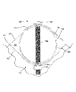
Perhaps more clearly shown in Figure 3A, the visible surface 110 of grill
skirt 106 is
substantially even and not deformed (i.e., the visible surface 110 has
maintained its aesthetic
appearance and structural integrity), particularly where the heads 108a of
fastening assemblies
108 are associated with the grill skirt 106.
Referring now to Figure 3B, a rear perspective view of assembly region 105 is
depicted.
As illustrated, the threaded rod 108b of fastening assembly 108 penetrates the
second assembly
piece (e.g., the support leg) 104 and the second connecting element 112.
Associated therewith
is a flat washer 108d and threaded nut 108c.
Perhaps best depicted by Figure 3C, assembly region 105 comprises a fastening
assembly, which as depicted is a mating pair of threaded fasteners comprising
a threaded bolt
108b and complementary threaded nut 108c with a flat washer 108d interposed
between the
two. In one or more implementations of the present disclosure, a flat washer
108d may be
excluded from the fastening assembly. Additionally or alternatively,
additional flat washers
may be used in positions known to and commonly used by those skilled in the
art. As illustrated
in Figure 3C, the head 108a of fastening assembly 108 is adjacent the visible
surface 110 of
the first assembly piece 106 (e.g., the grill skirt), and the flat washer 108d
is adjacent the second
connecting element 112 and adjacent the threaded nut 108c. In one or more
implementations
of the present disclosure, the fastening assembly may comprise any fastening
assembly known
in the art that fastens two or more objects by means of compression, including
without
limitation threaded mating pairs, rivets, and the like.
Upon tightening and/or compression of one or more components by the fastening
assembly 108, the second connecting element 112 may deform or otherwise be
compressed
towards the second assembly piece 104, which in turn presses a surface 116 of
the second
assembly piece 104 against an adjacent interior surface 118 of the first
connecting element 111.
In one or more implementations, and as depicted in Figure 3C, the surface 116
of the second
assembly piece 104 is complementary to at least a portion of the adjacent
surface 118 of the
first connecting element 111 such that the second assembly piece 104 acts as a
form to the first
connecting element 111, assisting in the distribution of forces applied to the
first connecting
element 111 during tightening of fastening assembly 108. In one or more
embodiments, such
- 7 -
CA 3008643 2018-06-18
distribution of force acts to maintain the substantially even surface of a
visible surface 110 of
the first assembly piece 106.
For the purposes of this disclosure, the term "substantially even surface" is
understood
to mean a surface that has not failed (e.g., deformed, bulged, dented, etc.)
as a result of
compressive forces applied directly or indirectly to the surface during
assembly of a device
comprising the surface. Thus, it should be understood that the term
"substantially even surface"
is made with reference to a surface belonging to any number or type of
contoured surfaces
(e.g., arcuate, flat, etc.). For example, an arcuate surface may comprise a
substantially even
surface along the contour of the arcuate surface insofar as the surface has
not failed (e.g.,
deformed, bulged, dented, etc.) as a result of compressive forces applied
during assembly of
the device comprising the arcuate surface. As another example, a grill skirt
comprising a
surface having two distinct planar surfaces (e.g., there is a designed groove
or depression on
the surface) maintains a substantially even surface if neither planar surface
fails (e.g., deforms,
bulges, dents, etc.) as a result of compressive forces applied during assembly
of the device
comprising the surface having two distinct planar surfaces.
In other words, and with particular reference to the exemplary embodiment of a
grill,
when the grill is assembled and the associated fasteners are tightened, the
second connecting
element may collapse and/or deform, pushing the leg into the interior surface
of the grill skirt.
In doing so, the leg becomes and/or acts as a form for the grill skirt, such
that additional
tightening of the threaded bolt and nut fastener causes the grill skirt to
conform to the contour
of the leg, if at all. In this manner, the aesthetic appearance of a visible
surface of the grill skirt
is maintained in addition to its structural integrity. This is in contrast to
a grill lacking a
collapsible and/or deformable second connecting element that experiences
denting and/or
deforming of the visible surface of the grill skirt¨and potentially affecting
the structural
integrity of the grill skirt, itself¨upon tightening of the fastening assembly
and coincident
localized compression of the grill skirt by the head of the fastener.
Furthermore, the collapsible and/or deformable second connecting element
allows the
leg to nestle against the grill skirt, and as the threaded bolt or other
fastener is tightened or
otherwise secured, the leg is forced into tighter association with the grill
skirt. As indicated
above, this maintains the visible surface of the grill skirt, but it also
provides other functional
benefits. For example, the legs are more securely fastened to the grill,
providing a sturdier
assembly. That is, in some embodiments, such an assembly is less likely to
result in a "wobbly"
leg. Instead, legs attached in such a manner are more likely to sit squarely
on the ground, which
provides the additional benefit of added stability to the assembled system.
- 8 -
CA 3008643 2018-06-18
Accordingly, the present invention may be applied to various assembled
systems,
including and apart from grills. For example, an assembled table may have legs
that attach to
an analogous skirt at the periphery of the table edge or may have sleeves with
a deformable
side that act in an analogous manner to secure the legs thereto, and in doing
so preserve the
aesthetic appearance and/or increase the structural integrity of the assembled
object.
In a similar fashion to that described above and with respect to Figures 1-4,
embodiments of the present disclosure may be applied to assembled systems
having any
number of shape of legs and/or skirt. In one embodiment, the legs are angular
(e.g., square,
polygonal, or similar.). In other embodiments, the legs are arcuate (e.g.,
circular¨as shown in
the accompanying figures¨oblong, or similar). In yet other embodiments, the
legs are a
combination of angular and arcuate geometries (e.g., frustoconical, etc.).
Generally, the legs
may be part of any assembled system, including, for example, chairs, tables,
desks, etc. and
may add additional benefits to assembled objects where the weight of the
surface above the
legs is greater or significantly greater than the weight of the associated
skirt (or analogous
component) as the legs are structurally reinforced through their forced
interaction with the skirt
(or analogous component).
As used herein, the term "analogous" generally connotes a comparable
relationship
between two things. For example, methods carried out in comparable ways (or
even
substantially the same way) or with comparable (or substantially the same)
components,
modules, etc., are understood to be analogous. In some instances, the term
"analogous"
connotes a counterpart of one or more components, elements, etc. For example,
a grill with
multiple legs may be attached to a single skirt. Each leg is considered
analogous to each other
leg of the same grill assembly. Similarly, legs from two similar or
substantially similar grills
are analogous as they serve the same or substantially the same function of
maintaining the grill
in an upright position. In the same or similar manner, a grill skirt may have
an analogous
component in a table or chair such that the analogous component maintains a
comparable
relationship (functional or otherwise) with the grill skirt. For example, an
analogous component
to a grill skirt existing on a table includes an angular form that receives an
angular table leg,
and one end of the angular analogous component deforms to force the leg to
conform to one or
more sides of the analogous component such that the leg provides additional
structural integrity
to the analogous component and/or increases the stability of the assembled
table, particularly
of the leg assembled thereto. Thus, analogous skirts and/or legs can be used
in one or more
embodiments of the present disclosure without departing from the scope of the
disclosure.
- 9 -
CA 3008643 2018-06-18
In one or more embodiments of the present disclosure, the first connecting
element is
the same as at least a portion of the first assembly piece.
In one or more implementations of the present disclosure, the second
connecting
element collapses and/or deforms. This may be implemented, for example, by
having a second
connecting element that is made of the same material as the first connecting
element but
wherein the thickness of the second connecting element is less than the
thickness of the first
connecting element. In such an implementation, the second connecting element
will fail (e.g.,
collapse and/or deform) under less compressive stress than the first
connecting element. In
doing so, the second connecting element, upon failure, will collapse towards
the second
assembly piece, causing the second assembly piece to be compelled toward the
first assembly
piece, and in one or more embodiments where the first connecting element and
the second
assembly pieces are complementary in shape, the second assembly piece acts as
a form to the
first connecting element. In such fashion, additional force applied to the
first connecting
element will cause a dispersion of the force to effectively maintain the
visible surface of the
.. first connecting element/first assembly piece in a substantially even
(e.g., undented and/or
undeformed) state.
In one or more embodiments of the present disclosure, the foregoing may be
accomplished in addition to or alternatively from differing the thicknesses of
the same material
by incorporating different materials into the first and/or second connecting
elements. For
example, a second connecting element may comprise one or more materials that
deform under
less compressive stress than one or more materials comprising the first
connecting element. As
a non-limiting example, the first connecting element may comprise steel,
whereas the second
connecting element may comprise aluminum or an aluminum alloy that is defined
by a higher
degree of malleability. In other words, the metal comprising the second
connecting element
will deform under less compressive and/or concussive force than the metal
comprising the first
connecting element to accomplish substantially the same purpose of deformation
described
above with respect to first and second connecting elements having differing
thicknesses.
In one or more implementations of the present disclosure, the second material
comprises a thermoplastic elastomer or other flexible plastic and/or elastomer
or any other
material known to those having skill in the art that would cause the second
connecting element
to collapse before the first connecting element and/or any portion of the
first assembly piece.
In one or more implementations of the present disclosure, the first and second
connecting elements may comprise the same (or a different) material, wherein
the second
connecting element comprises pre-weakened sections and/or perforated sections
that will cause
- 10 -
CA 3008643 2018-06-18
the second connecting element to collapse and/or deform as a result of a
compressive stress
that does not cause the first connecting element (and in some implementations
the first
connecting piece) to deform or otherwise fail, thereby maintaining a visible
surface of the first
connecting piece that is substantially even.
With continued reference to Figure 3, the second assembly piece 104 is
depicted as
being positioned within an opening 120 defined by the first and second
connecting elements
111, 112. Stated another way, the second assembly piece 104 is shaped to fit
within an opening
120 defined by the first and second connecting elements 111, 112. In one or
more
implementations of the present disclosure, the second assembly piece 104 is
associated with a
plurality of fastening assemblies 108. As depicted in Figure 3, the second
assembly piece 104
is associated with two fastening assemblies 104. In one or more
implementations, the first and
second assembly pieces 106, 104 are associated with a single fastening
assembly 108. The
number and/or type of fastening assemblies may vary insofar as at least one
fastening assembly
108 is associated with at least one pair of first and second assembly pieces
106, 104.
Referring now to Figure 4, depicted is a flow diagram illustrating an
exemplary method
400 for assembling a device while maintaining the aesthetic appearance and
structural integrity
of a visible surface according to one or more implementations of the present
disclosure. The
method of Figure 4 may comprise step 402 of aligning a first assembly piece
with a second
assembly piece, wherein the first assembly piece comprises a first connecting
element and a
second connecting element. In one or more implementation of the present
disclosure, step 402
may be practiced when assembling a grill as illustrated in Figures 1-3. More
particularly, step
402 may comprise aligning a grill skirt with a support leg, where the grill
skirt has a
substantially even visible surface and the support leg is shaped to fit within
an opening of an
assembly region defined by first and second connecting elements of the grill
skirt.
The method of Figure 4 may further comprise step 404 of securing the first
assembly
piece to the second assembly piece using a fastening assembly configured to
compress the first
connecting element, the second connecting element, and the second assembly
piece together.
In one or more implementations of the present disclosure, step 404 may
comprise securing a
grill skirt to a support leg using a threaded mating pair that spans the grill
skirt and support leg.
The method of Figure 4 may further comprise step 406 of tightening the
fastening
assembly such that the second connecting element deforms, thereby pressing a
surface of the
second assembly piece against an adjacent surface of the first connecting
element such that a
visible surface of the first connecting piece retains a substantially even
surface. In one or more
implementations of the present disclosure, step 406 may comprise tightening a
threaded mating
- 11 -
CA 3008643 2018-06-18
pair, causing the second connecting element to deform and press the support
leg into an interior
surface of the grill skirt. The support leg may then act as a form to keep the
grill skirt from
deforming as a result of the compressive forces applied by the threaded mating
pair¨in essence
maintaining a substantially even visible surface on the grill skirt.
Various alterations and/or modifications of the inventive features illustrated
herein, and
additional applications of the principles illustrated herein, which would
occur to one skilled in
the relevant art and having possession of this disclosure, can be made to the
illustrated
embodiments without departing from the spirit and scope of the invention as
defined by the
claims, and are to be considered within the scope of this disclosure. Thus,
while various aspects
and embodiments have been disclosed herein, other aspects and embodiments are
contemplated. While a number of methods and components similar or equivalent
to those
described herein can be used to practice embodiments of the present
disclosure, only certain
exemplary components and methods are described herein.
It will also be appreciated that systems, devices, products, kits, methods,
and/or
processes, according to certain embodiments of the present disclosure may
include,
incorporate, or otherwise comprise properties, features (e.g., components,
members, elements,
parts, and/or portions) described in other embodiments disclosed and/or
described herein.
Accordingly, the various features of certain embodiments can be compatible
with, combined
with, included in, and/or incorporated into other embodiments of the present
disclosure. Thus,
disclosure of certain features relative to a specific embodiment of the
present disclosure should
not be construed as limiting application or inclusion of said features to the
specific
embodiment. Rather, it will be appreciated that other embodiments can also
include said
features, members, elements, parts, and/or portions without necessarily
departing from the
scope of the present disclosure.
Moreover, unless a feature is described as requiring another feature in
combination
therewith, any feature herein may be combined with any other feature of a same
or different
embodiment disclosed herein. Furthermore, various well-known aspects of
illustrative systems,
methods, apparatus, and the like are not described herein in particular detail
in order to avoid
obscuring aspects of the example embodiments. Such aspects are, however, also
contemplated
herein.
Various aspects of the present disclosure, including devices, systems, and
methods may
be illustrated with reference to one or more embodiments or implementations,
which are
exemplary in nature. As used herein, the term "exemplary" means "serving as an
example,
instance, or illustration," and should not necessarily be construed as
preferred or advantageous
- 12 -
CA 3008643 2018-06-18
over other embodiments disclosed herein. In addition, reference to an
"implementation" of the
present disclosure or invention includes a specific reference to one or more
embodiments
thereof, and vice versa, and is intended to provide illustrative examples
without limiting the
scope of the invention, which is indicated by the appended claims rather than
by the following
description.
As used throughout this application the words "can" and "may" are used in a
permissive
sense (i.e., meaning having the potential to), rather than the mandatory sense
(i.e., meaning
must). Additionally, the terms "including," "having," "involving,"
"containing,"
"characterized by," as well as variants thereof (e.g., "includes," "has,"
"involves," "contains,"
etc.), and similar terms as used herein, including within the claims, shall be
inclusive and/or
open-ended, shall have the same meaning as the word "comprising" and variants
thereof (e.g.,
"comprise" and "comprises"), and do not exclude additional un-recited elements
or method
steps, illustratively.
It will be noted that, as used in this specification and the appended claims,
the singular
-- forms "a," "an" and "the" include plural referents unless the context
clearly dictates otherwise.
Thus, for example, reference to a singular referent (e.g., "widget") includes
one, two, or more
referents. Similarly, reference to a plurality of referents should be
interpreted as comprising a
single referent and/or a plurality of referents unless the content and/or
context clearly dictate
otherwise. For example, reference to referents in the plural form (e.g.,
"widgets") does not
necessarily require a plurality of such referents. Instead, it will be
appreciated that independent
of the inferred number of referents, one or more referents are contemplated
herein unless stated
otherwise.
The present disclosure may be embodied in other specific forms without
departing from
its spirit or essential characteristics. The described embodiments are to be
considered in all
respects only as illustrative and not restrictive. The scope of the invention
is, therefore,
indicated by the appended claims rather than by the foregoing description.
While certain
embodiments and details have been included herein and in the attached
disclosure for purposes
of illustrating embodiments of the present disclosure, it will be apparent to
those skilled in the
art that various changes in the methods, products, devices, and apparatus
disclosed herein may
be made without departing from the scope of the disclosure or of the
invention, which is defined
in the appended claims. All changes which come within the meaning and range of
equivalency
of the claims are to be embraced within their scope.
- 13 -
CA 3008643 2018-06-18