Note: Descriptions are shown in the official language in which they were submitted.
Waterjet Cutting Tool
Related Application
This application claims priority to U.S. Provisional Patent Application No.
62/521,800, filed June 19,
2017, herein incorporated by reference in its entirety.
Technical Field
The invention relates to cutting tools and more specifically to waterjet
cutting tools for use in cutting
wellbore casings and components used in or associated to wellbore casings.
Background
Oilfield wellheads and spools have various attachments, referred to herein and
encompassed by the
expression wellbore casings and associated components, that require
adjustment, replacement, or
removal from time to time through normal operation of the well, or in the
process of abandonment of the
well. These components can be difficult to remove when corroded or otherwise
worn or seized in place.
Conventional hand tools may not be effective in removing these components and
"hot methods" such
as torch cutting, heating, drilling and machining for removal are often not
acceptable because of the
explosive nature of the well and its environment.
To use conventional methods requires that the well be isolated through
different processes that are time
consuming and expensive. Conventional methods can also cause damage to the
wellhead, casings or
related or associated components.
Safer and/or more convenient methods are desired to eliminate or reduce the
risk of explosion and/or
to provide faster or more convenient setup, adjustment and/or cutting and/or
to carry out less costly
component removal for repairs or abandonment.
Summary of the Invention
A waterjet cutting tool that connects to a wellbore casing or suitable
associated component thereof is
provided. The waterjet cutting tool uses a cutting solution, typically
comprising water and an abrasive,
that may be used to cut various components of a well including for example a
wellbore casing, flanges,
connectors, liners, valves, piping, etc. The waterjet cutting tool includes
both a radial adjustment
capability and an annular adjustment capability allowing for movement of the
cutting nozzle about at
least a portion of the wellbore casing. In this way, various components of the
well may be cut and
CA 3008735 2018-06-18
removed as necessary to carry out maintenance, replacement of components,
additional of components
and/or abandonment of the well as desired.
In one embodiment, the present invention provides for a waterjet cutting tool
for radial connection to a
wellbore casing for cutting the wellbore casing or suitable components
thereof, the waterjet cutting tool
comprising:
a waterjet nozzle for outputting a cutting solution at high pressure, the
waterjet nozzle for
connection to a cutting solution source;
a radial adjustment unit for radially associating the waterjet nozzle to the
wellbore; and
an annular adjustment assembly for mount of the waterjet nozzle thereto, for
allowing annular
movement of the waterjet nozzle about a vertical axis of the wellbore.
In a further embodiment of the waterjet cutting tool or tools as outlined
above, the tool further comprises
a carriage assembly in communication with the radial adjustment unit and the
annular adjustment
assembly, onto which the waterjet nozzle is directly or indirectly mounted.
In a further embodiment of the waterjet cutting tool or tools as outlined
above, the waterjet cutting tool
further comprises a connection device for associating the waterjet cutting
tool to the wellbore casing or
suitable component thereof.
In a further embodiment of the waterjet cutting tool or tools as outlined
above, the connection device
comprises:
a spigot shaft for insertion into a tubing hanger,
a spigot adapter for connection with the spigot shaft and securely placeable
in a tubing hanger
of the wellbore casing;
a bearing mounted on the spigot shaft; and
a sector gear bracket connected to the bearing onto which a component of the
annular
adjustment assembly may be connected.
In a further embodiment of the waterjet cutting tool or tools as outlined
above, the radial adjustment unit
is radially adjustable relative a vertical axis of the wellbore by means of a
radially adjusting assembly.
In a further embodiment of the waterjet cutting tool or tools as outlined
above, the radially adjusting
assembly comprises a adjustment member for radial orientation relative the
wellbore and an adjustment
control operationally associated with the adjustment member for controlling
the radial distance of the
waterjet nozzle from the wellbore casing or suitable component.
2
CA 3008735 2018-06-18
In a further embodiment of the waterjet cutting tool or tools as outlined
above, the carriage assembly
and radial guide track each comprise a guide element adapted for interaction
therebetween for guiding
the carriage assembly along the radial guide track.
In a further embodiment of the waterjet cutting tool or tools as outlined
above, the radial adjusting
assembly is integrated into the carriage assembly.
In a further embodiment of the waterjet cutting tool or tools as outlined
above, the adjustment member
is a threaded member and the adjustment control is a hand wheel or powered
wheel.
In a further embodiment of the waterjet cutting tool or tools as outlined
above, the annular adjustment
assembly comprises an annular sector gear track for interaction with a
carriage pinion gear mounted on
the carriage assembly for guiding the carriage assembly along the sector gear
track thereby adjusting
the annular position of the nozzle when the carriage pinion gear is activated.
In a further embodiment of the waterjet cutting tool or tools as outlined
above, the annular sector gear
track has an annular curve such that movement along the annular sector gear
track by the carriage
assembly maintains a substantially consistent distance of the carriage
assembly from the vertical axis
of the wellbore when the cutter tool is connected to the wellbore casing.
In a further embodiment of the waterjet cutting tool or tools as outlined
above, the tool further comprises
a drive motor for driving the carriage assembly along the annular sector gear
track.
In a further embodiment of the waterjet cutting tool or tools as outlined
above, the drive motor is a
carriage drive motor and the carriage pinion gear is a drive gear and the
carriage drive motor is in
connection with the carriage pinion drive gear for driving the carriage
assembly along the annular sector
gear track.
In a further embodiment of the waterjet cutting tool or tools as outlined
above, the annular adjustment
assembly further comprises a waterjet nozzle position adjustment assembly for
vertically and/or
horizontally adjusting the position of the waterjet nozzle.
3
CA 3008735 2018-06-18
In a further embodiment of the waterjet cutting tool or tools as outlined
above, the waterjet nozzle
position adjustment assembly allows for 3-dimensional adjustment and
orientation of the waterjet
nozzle.
In yet a further embodiment, the present invention provides for a waterjet
cutting tool for radial
connection to a wellbore casing for cutting the wellbore casing or suitable
components thereof, the
waterjet cutting tool comprising:
a waterjet nozzle for outputting a cutting solution at high pressure, the
waterjet nozzle for
connection to a cutting solution source;
a radial adjustment unit for radially associating the waterjet nozzle to the
wellbore;
an annular adjustment assembly for mount of the waterjet nozzle thereto, for
allowing annular
movement of the waterjet nozzle about a vertical axis of the wellbore;
a carriage assembly in communication with the radial adjustment unit and the
annular adjustment
assembly, onto which the waterjet nozzle is directly or indirectly mounted;
and
a connection device for associating the waterjet cutting tool to the wellbore
casing or suitable component
thereof, the connection device comprises:
a spigot shaft for insertion into a tubing hanger,
a spigot adapter for connection with the spigot shaft and securely placeable
in a tubing hanger of the
wellbore casing;
a bearing mounted on the spigot shaft; and
a sector gear bracket connected to the bearing onto which a component of the
annular adjustment
assembly may be connected.
Brief Description of the Drawings
Figure 1 is an isometric view illustrative of one embodiment of a waterjet
cutting tool connected to a
casing head of a wellbore wherein the waterjet nozzle is oriented to cut in a
horizontal cutting position;
Figure 2 is a side view illustrative of one embodiment of the waterjet cutting
tool shown in Figure 1
connected to a casing head of a wellbore wherein the waterjet nozzle is
oriented to cut in a horizontal
cutting position;
Figures 3A and 3B are a side view and an isometric view, respectively,
illustrative of one embodiment
of a waterjet cutting tool;
4
CA 3008735 2018-06-18
Figure 4A is a top view illustrative of one embodiment of one embodiment of a
waterjet nozzle of a
waterjet cutting tool oriented to cut a component associated to a wellbore
casing in the form of a flange
connection stud;
Figure 4B is a top view illustrative of one embodiment of the waterjet cutting
tool of Figure 4A oriented
to cut a component associated to a wellbore casing in the form of a flange
connection stud;
Figure 5 is a side view illustrative of one embodiment of a waterjet cutting
tool connected to a casing
head of a wellbore wherein the waterjet nozzle is oriented to cut in a
vertical cutting position;
Figure 6 is an isometric view illustrative of one embodiment of the waterjet
cutting tool shown in Figure
6 connected to a casing head of a wellbore wherein the waterjet nozzle is
oriented to cut in a vertical
.. cutting position;
Figure 7 is an isometric view illustrative of another embodiment of a waterjet
cutting tool mounted to the
wellhead view a spigot adapter;
Figure 8 is a cross-sectional view of the waterjet cutting tool shown in
Figure 7; and
Figure 9 is an isometric view illustrative of one embodiment of a spigot
adapter that can be used with
the waterjet cutting tool shown, for example, in Figure 7.
Detailed Description
Described herein are embodiments of waterjet cutting tools and methods of
making and using same
that are intended to be illustrative of the inventive concept and are not
intended to be limiting in any
way. Various modifications, adjustments, revisions, substitutions and/or
alterations to the tools, methods
and uses described herein may be carried out without departing from the scope
or spirit of the invention
and are intended to be within the scope of the invention.
It will be appreciated that reference to a wellbore casing or casing herein is
intended to also encompass
any suitable components associated to a wellbore casing that a waterjet
cutting tool may be used to cut,
mount thereto, or brace thereagainst, including but not limited to, a wellbore
head and/or wellhead,
casings, casing hangers, flanges, connectors and components thereof including
studs, dog bolts, etc.,
piping, valves, liners, strings, production well casings and components
thereof, steam injection wells
and components thereof, etc.
Further, it will be appreciated that reference to a wellbore casing or casing
when used in connection
with the attachment or association of the waterjet cutting tool encompasses
but is not limited to the
5
CA 3008735 2018-06-18
attachment of the waterjet cutting tool to a wellbore casing, casing head,
suitable flange, wellhead or
any suitable generally round or cylindrical component of the well onto which
the cutting tool may be
connected or associated. Attachment of the waterjet cutting tool to a central
component of the well, such
as the tubing hanger via a spigot adapter that threads into the tubing hanger,
that is at the center of the
wellhead is ideal. Attachment to central component allows for ease of set up,
manipulation of the cutter
about the casing and ease of adjustment between cuts as the waterjet cutting
tool is connected to a
centralized position and is therefore more easily centered itself and more
easily manoeuvered about a
central position for making cuts.
In various embodiments, the present invention provides for a waterjet cutting
tool that may be connected
to a wellbore casing, or suitable associated or related components thereof as
referred to above such as
a casing head or mating flange, for cutting the wellbore casing or suitable
components thereof using a
suitably high pressure cutting solution.
In certain embodiments of the waterjet cutting tool, a waterjet nozzle may
annularly rotate about the
wellbore casing or a vertical axis thereof for at least a portion of the
circumference of the wellbore casing
allowing for cutting of the wellbore casing. The waterjet cutting tool may
also be adapted such that it
maintains the waterjet nozzle at a substantially consistent radial distance
from the wellbore casing as it
is rotated about the casing.
In this way, various components of the well may be cut and removed as
necessary to carry out
maintenance, replacement of components, additional of components and/or
abandonment of the well
as desired.
One embodiment of a waterjet cutting tool is shown with reference to Figures 1
to 4B wherein the
waterjet cutting tool is shown in a substantially horizontal cutting
orientation while the waterjet cutting
tool is shown in a substantially vertical cutting orientation with reference
to Figures 5 and 6 and is shown
generally at 100 throughout Figures 1 to 6. The waterjet cutting tool is also
shown using an alternative
attachment device in Figures 7 to 9, wherein the waterjet cutting tool is
attached to the wellhead using
a spigot adaptor threaded into the tubing hanger.
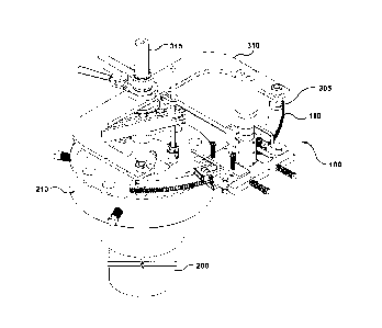
In Figures 1 and 2, the waterjet cutting tool 100 is shown connected to a
casing head 210. In the
embodiments shown throughout Figures 1 to 6, the tool 100 is comprised of a
radial adjustment
assembly, an annular adjustment assembly and a waterjet nozzle 120. The radial
adjustment assembly
is used to adjust the radial spacing of the waterjet nozzle 120 laterally from
the well casing 200 or a
vertical axis thereof onto which the tool 100 is attached. The annular
adjustment assembly is used to
allow annular movement of the waterjet nozzle 120 about the casing 200 or a
vertical axis thereof. In
6
CA 3008735 2018-06-18
various embodiments the annular adjustment assembly is annularly curved such
that a consistent radial
distance of the waterjet nozzle 120 from the well casing 200 may be maintained
during annular
movement of the waterjet nozzle 120 by adjusting the radial distance. The
waterjet nozzle 120 is used
to cut the casing 200 or suitable components thereof.
In the embodiments shown in Figures 1 to 6, the radial adjustment assembly
comprises a connection
device for associating the tool 100 to the wellbore casing. In the embodiments
shown the connection
device is a magnet 115 which may be optionally clamped to the casing 200 or
suitable components
thereof such as the casing head 210, the mating flange 215. or the wellhead or
component thereof such
as the tubing hanger or spigot adapter (as discussed in more detail with
reference to Figures 7 to 9), to
further secure tool 100 to the well casing 200. It will be appreciated that
reference herein to "association"
or "connection" or "attachment" is interchangeable and each term encompasses a
disconnectable
connection of the tool to the well casing and encompasses both a magnetic
association to the well
casing as well as or alternatively any suitable connections or attachment
mechanism including but not
limited to a clamped, bolted or threaded connection or bracket or welded
connection and encompasses
any suitable connecting or associated means or devices that may be used to
connect the tool 100 to a
wellbore casing. Further, although a single magnet is shown, any suitable
number of magnets may be
used alone or in conjunction with further attachment means or mechanisms.
As outlined above, the tool may alternatively be attached to the spigot
adapter threaded into the tubing
hanger. This centers the tool about a centralized position thereby maintaining
the tool a consistent radial
.. distance during annular rotation of the tool. The spigot adapter may be
installed first into the tubing
hanger as well as the shaft. The cutting tool can then be installed on the
shaft with a bearing and the
height of the tool can be adjusted to orient the nozzle in a desired location.
In addition, to help reduce flexing of the tool when pressurized or during
changes in pressurization, one
or more stabilizer arms may be employed to brace the tool, for example,
against the wellhead, casing,
or suitable components thereof.
The radial adjustment assembly also comprises a radial adjustment unit 105 for
allowing adjustment of
the radial distance of the nozzle 120 laterally from the well casing 200. This
may include for example a
threaded rod or component that may be rotated by a hand wheel 135, or machine
driven mechanism
causing radial movement of the nozzle 120. It will be appreciated that any
suitable device or setup may
be used that allows for radial adjustment such as a scissor mechanism, and the
invention is not limited
to threaded adjustment and encompasses both hand and mechanised operation of
the adjustment
assembly.
7
CA 3008735 2018-06-18
Attached to the radial adjustment assembly is the annular adjustment assembly.
In the embodiments
shown in Figures 1 to 6 the annular adjustment assembly comprises a radial
guide track 145 having an
annular shape. The radial guide track 145 supports a sector gear track 110
onto which a carriage
assembly 170 is mounted. The carriage assembly 170 includes a carriage pinion
gear 155 in operational
contact with the sector gear track 110 allowing annular movement of the
carriage assembly 170 along
the sector gear track 110. The waterjet nozzle 120 is mounted to the carriage
assembly 170 and thus is
annularly moved about the casing 200 or a vertical axis thereof as the
carriage assembly 170 moves
along the sector gear track 110. The radial guide track 145 and/or the sector
gear track 110 may be
adapted to extend around a portion of the circumference of the casing or may
be adapted to extend
about the full circumference of the casing in which case at least the sector
gear 110 would be a full ring.
By controlling the radial adjustment unit 105 to adjust the radial distance
between the carriage assembly
170 and the casing 200, a proper radial distance may be selected that allows
for a substantially
consistent distance between the carriage assembly 170 and attached nozzle 120
and the casing or the
vertical axis thereof during travel of the carriage assembly 170 along the
sector gear track 110.
It will be appreciated that the sector gear track 110 and the carriage pinion
gear 155 are simply
illustrative of one potential setup for allowing annular movement of the
carriage assembly about the
casing or vertical axis thereof. Any suitable setup may be used, for example a
track with ball bearings,
a track with wheels, a tongue and grove, etc. for guiding the carriage
assembly 170 annularly about the
casing.
As shown in Figures 7 to 9 and outlined above, the cutting tool 100 may
alternatively be attached to the
tubing hanger via a spigot shaft 315 and spigot adapter 335 threaded into the
tubing hanger in the
casing 200. This centers the cutting tool 100 about a centralized position
thereby maintaining the tool
at a consistent radial distance during annular rotation of the cutting tool
100 facilitating cutting of the
casing and suitable components. The spigot adapter 335 may be installed first
into the tubing hanger
as well as the spigot shaft 315. The cutting tool 100 can then be installed on
the spigot shaft 315 with a
bearing 340 onto which a sector gear bracket 310 is connected. Clamps 320 and
325 may be used as
needed to orient the height of the bearing 340 on the spigot shaft 315. The
clamps 320 and 325 may be
fast-action clamps 330 to aid in quick connection and adjustment of the
bearing 340.
The bracket 310 is rotatable about the spigot shaft 315 and mounts to the
sector gear track 110 and
can replace the radial guide track 145 shown in Figures Ito 6. The bracket 310
can be mounted to the
sector gear track or other suitable component of the annular adjustment
assembly via any suitable
connecting or mounting device, for example using bolts 305.
8
CA 3008735 2018-06-18
The height of the tool 100 on the spigot shaft 315 can be adjusted to orient
the nozzle (not shown in
Figures 7 to 9) in a desired location.
It will be appreciated that spigot adapters 335 of various different sizes and
diameters may be used to
accommodate different tubing hangers.
In addition, to help reduce flexing of the cutting tool 100 when pressurized
or during changes in
pressurization, one or more stabilizer arms may be employed to brace the tool,
for example, against the
wellhead, casing, or suitable components thereof. The stabilizer arms may be
bolted, clamped or even
welded in place to aid in further bracing the cutting tool 100.
The carriage assembly 170 may then be radially adjusted to control the radial
distance of the cutting
nozzle from the casing 200 or suitable component.
The waterjet nozzle 120 is mounted to the annular adjustment assembly and, in
the embodiments
shown, the carriage assembly 170, with a nozzle position adjustment assembly
140 that can allow for
various adjustment and orientation of the nozzle 120. This may include
vertical, lateral and/or horizontal
adjustment of the nozzle 120 allowing for limited or full 3-dimensional
adjustment of the nozzle 120.
This allows for suitable alignment and/or orientation of the nozzle 120
relative the surface or component
to be cut. For example, as shown in Figures 1 and 2, the nozzle 120 has been
oriented to cut in the
area between the casing head 210 and the mating flange 215. A substantially
horizontal orientation is
shown. This may be used to cut the casing 200 or components thereof including
the flange connection
studs 220, dog bolts, etc. If desired, the pressure of the cutting solution,
typically a mixture of water and
sand, may be adjusted such that certain components proximate the nozzle 120
are cut while
components further away remain intact. In this way, for example, the nozzle
120 may be oriented to cut
the flange connection studs 220 without cutting the well casing 200.
The nozzle position adjustment assembly 140 may include various clamps, rods
and hinges, ball joints
or shoulder joints for example as needed to allow for greater adjustment
ability. The person of skill in
the art will be aware of the various components needed to allow for greater
flexibility of the movement
and orientation of the nozzle 120.
The person of skill in the art will be aware of suitable cutting pressures and
ratios of water to sand or
other suitable abrasives. In one example, a suitable cutting pressure may be
between 10,000 to 50,000
psi. Pressure may also be regulated during cutting if, for example, the radial
distance between the
surface to be cut and the nozzle 120 fluctuates.
9
CA 3008735 2018-06-18
Any suitable waterjet cutting nozzle 120 may be used for cutting well casings
and components
associated thereto. The cutting nozzle 120 shown in Figures 1 to 6 comprises a
dual coupler 160, the
first coupler for input of water and the second coupler for input of sand or
other suitable abrasive.
A carriage drive motor 130 may be used to drive the carriage along the radial
guide track about the
vertical axis of the casing. In the embodiments shown, the carriage drive
motor 130 drives the carriage
pinion gear 155 as the carriage pinion gear 155 is a pinion drive gear. It
will be appreciated that any
suitable drive motor may be used or may optionally by driven by hand or other
suitable power sources.
The nozzle 120 is typically placed in a generally perpendicular orientation
relative the surface to be cut
and the nozzle position adjustment assembly 140 may be used to obtain proper
or desirable orientation
of the nozzle 120 relative the surface. One orientation for cutting a flange
connection stud 220 is shown
with reference to Figures 4A and 4B. Although the annular adjustment assembly
is setup to guide the
carriage assembly 170 about the casing 200 or a vertical axis thereof, the
nozzle position adjustment
assembly 140 may be used to orient the nozzle 120 to cut components of the
casing which are off-
center or off-axis such as the flange connection studs 220. In such a setup,
the nozzle 120 may be
oriented to a suitable cutting position relative the connection studs 220 and
the carriage assembly 170
may be guided annularly along the annular adjustment assembly a suitable
distance to cut the flange
connection stud 220. The nozzle 120 may then be moved to the next stud 220 to
be cut and the nozzle
re-activated to cut the next stud 220.
The tool 100 may also be used to cut internal components of the casing and
casing assembly a sleeve
240 or retaining bolts 230 as shown with reference to Figures 5 and 6. As
such, the nozzle position
adjustment assembly 140 may be used to orient the nozzle 120 in a suitable
cutting position such as a
vertical cutting position. The nozzle 120 may then be activated to cut
components as needed in similar
manner as that outlined above.
It will be appreciated that the present invention has been described with
reference to various
embodiments and examples, all of which are intended for illustrative and non-
limiting purposes. Various
modifications, alterations, adjustments, substitutions and revisions may be
made without departing from
the scope or spirit of the invention.
CA 3008735 2018-06-18