Note: Descriptions are shown in the official language in which they were submitted.
=
CA 03009050 2018-06-18
Description_JT-081PCT
POWER SUPPLY ASSEMBLY, NON-COMBUSTION-TYPE FLAVOR INHALER,
AND NON-COMBUSTION-TYPE FLAVOR INHALATION SYSTEM
TECHNICAL FIELD
[0001]
The present invention relates to a power supply assembly including a power
supply for supplying power to an atomizer that atomizes an aerosol source
without
combustion, a non-combustion-type flavor inhaler including the power supply
assembly. and a non-combustion-type flavor inhalation system including the non-
combustion-type flavor inhaler.
BACKGROUND ART
[0002]
A non-combustion-type flavor inhaler (electric smoking article) that provides
a flavor without combustion of a flavor source, such as tobacco, has been
proposed
instead of a cigarette. Patent Literature 1 discloses an electric smoking
article having
an aerosol generation source. The electric smoking article includes: a liquid
storage
that stores a liquid; a heater that vaporizes the liquid sent from the liquid
storage; and a
power supply that supplies power to the heater. Patent Literature 1 discloses
a
technique of preventing the electric smoking article from being used by an
unauthorized user, with application of a user authentication technique.
CITATION LIST
PATENT LITERATURE
[0003]
Patent Literature 1: WO 2014/150704 A
SUMMARY
[0004]
A first feature is a non-combustion-type flavor inhaler including: an
atomization assembly including an atomizer configured to atomize an aerosol
source
without combustion; and a power supply assembly including a power supply for
supplying power to the atomizer. The power supply assembly includes: paired
electrodes for electrical connection with the atomizer; and a first electrode
and a
second electrode electrically connected with the power supply. At least one of
the
1
CA 03009050 2018-06-18
Description_JT-081PCT
first electrode and the second electrode is electrically connectable to a
charger for
charging the power supply. The non-combustion-type flavor inhaler is provided
with
a control circuit configured to detect a predetermined current in an opposite
direction
to a direction of a current flowing through the first electrode or the second
electrode
when the charger charges the power supply.
[0005]
The second feature is the non-combustion-type flavor inhaler according to the
first feature, wherein the power supply is configured to generate the
predetermined
current to be supplied to the control circuit.
[0006]
The third feature is the non-combustion-type flavor inhaler according to the
first feature or the second feature, wherein the power supply assembly
includes a first
case housing the power supply, the first case including first paired
electrodes being the
paired electrodes, the atomization assembly includes a second case housing the
atomizer, the second case including second paired electrodes, the second case
being
detachably attachable to the first case, and the first paired electrodes and
the second
paired electrodes are configured to electrically connect together when the
first paired
electrodes and the second paired electrodes are in contact with each other.
[0007]
The fourth feature is the non-combustion-type flavor inhaler according to the
third feature, wherein at least one of the first case and the second case
includes an
engagement for engaging the first case and the second case together.
[0008]
The fifth feature is the non-combustion-type flavor inhaler according to the
third feature or the fourth feature, wherein, with the first paired electrodes
and the
second paired electrodes electrically connected together, the first electrode
and the
second electrode are disposed at positions at which an external element
different from
constituent elements of the non-combustion-type flavor inhaler enables the
first
electrode and the second electrode to be in conduction.
[0009]
The sixth feature is the non-combustion-type flavor inhaler according to any
one of the third feature to the fifth feature, wherein, with the first paired
electrodes and
the second paired electrodes electrically connected together, each of the
first electrode
and the second electrode have a portion exposed on a surface of the first
case.
[0010]
2
CA 03009050 2018-06-18
Description_JT-081PCT
The seventh feature is the non-combustion-type flavor inhaler according to
any one of the third feature to the fifth feature, wherein, with the first
paired electrodes
and the second paired electrodes electrically connected together, the first
paired
electrodes are disposed at positions at which conduction of an external
element
different from constituent elements of the non-combustion-type flavor inhaler,
is not
allowed between the first paired electrodes.
[0011]
The eighth feature is the non-combustion-type flavor inhaler according to the
seventh feature, wherein, with the first paired electrodes and the second
paired
electrodes electrically connected together, at least one of the first paired
electrodes is
not exposed on a surface of the non-combustion-type flavor inhaler.
[0012]
The ninth feature is the non-combustion-type flavor inhaler according to the
sixth feature, wherein an exposed portion of the first electrode and an
exposed portion
of the second electrode are disposed on faces facing mutually different
directions in
the first case.
[0013]
The tenth feature is the non-combustion-type flavor inhaler according to the
sixth feature, wherein an exposed portion of the first electrode and an
exposed portion
of the second electrode are disposed on faces facing identical directions in
the first
case, and a difference in level is provided between an end face of the exposed
portion
of the first electrode and an end face of the exposed portion of the second
electrode.
[0014]
The eleventh feature is the non-combustion-type flavor inhaler according to
any one of the first feature to the tenth feature, wherein both of the first
electrode and
the second electrode are electrically connectable to the charger for charging
the power
supply, and the power supply is configured to be charged by the charger
through the
first electrode and the second electrode.
[0015]
The twelfth feature is the non-combustion-type flavor inhaler according to any
one of the first feature to the eleventh feature, wherein the control circuit
includes: a
detector configured to detect the predetermined current; and a rectifying
element
configured to prevent a charging current from flowing in the detector.
[0016]
The thirteenth feature is the non-combustion-type flavor inhaler according to
3
CA 03009050 2018-06-18
Description_JT-081PCT
the twelfth feature, wherein the rectifying element includes an anode and a
cathode,
the anode is electrically connected with the detector, and the cathode is
electrically
connected with an electrode positive during the charging by the charger, among
the
first electrode and the second electrode.
[0017]
The fourteenth feature is the non-combustion-type flavor inhaler according to
any one of the first feature to the tenth feature, wherein the power supply is
configured
to be charged by the charger through one of the first electrode and the second
electrode.
[0018]
The fifteenth feature is the non-combustion-type flavor inhaler according to
any one of the first feature to the tenth feature, wherein the power supply
assembly
includes a third electrode different from the first electrode and the second
electrode,
and the charging current is configured to be supplied from the charger to the
power
supply through the third electrode and only one of the first electrode and the
second
electrode.
[0019]
The sixteenth feature is the non-combustion-type flavor inhaler according to
the fifteenth feature, wherein an electrode that does not contribute to supply
of the
charging current supplied from the charger to the power supply, among the
first
electrode and the second electrode is: provided at a position at which the
electrode is
physically out of contact with the charger; physically in contact with the
charger
through an insulator preventing electrical connection with the charger; or
electrically
connected with the charger and does not contribute to the supply of the
charging
current from the charger to the power supply.
[0020]
The seventeenth feature is the non-combustion-type flavor inhaler according
to any one of the first feature to the sixteenth feature, wherein the control
circuit is
configured to control a power from the power supply to the atomizer.
[0021]
The eighteenth feature is the non-combustion-type flavor inhaler according to
the seventeenth feature, wherein the controller is configured to perform a
predetermined control in response to a length of a period of the predetermined
current
detected by the control circuit.
[0022]
The nineteenth feature is the non-combustion-type flavor inhaler according to
4
CA 03009050 2018-06-18
Description_JT-08 I PCT
the seventeenth feature or the eighteenth feature, wherein the control circuit
is
configured to perform a predetermined control when the control circuit has
detected
the predetermined current a plurality of times within a predetermined period.
[0023]
The twentieth feature is the non-combustion-type flavor inhaler according to
the eighteenth feature or the nineteenth feature, wherein the control circuit
cancels the
predetermined control when the control circuit has continuously detected the
predetermined current for a predetermined time or more.
[0024]
The twenty-first feature is the non-combustion-type flavor inhaler according
to any one of the seventeenth feature to the twentieth feature, wherein, the
control
circuit is configured to perform a predetermined control based on a level of
an electric
resistance value of the external element when the control circuit detects the
predetermined current generated by an external element different from
constituent
elements of the non-combustion-type flavor inhaler,
[0025]
The twenty-second feature is the non-combustion-type flavor inhaler
according to any one of the seventeenth feature to the twenty-second feature,
wherein
the control circuit detects whether the power supply is being charged, and the
control
circuit does not perform a predetermined control regardless of a detected
result of the
predetermined current when detecting the charging of the power supply.
[0026]
A twenty-third feature is a non-combustion-type flavor inhalation system
comprising: the non-combustion-type flavor inhaler according to any one of the
first
feature to the twenty-second feature; and a charger detachably attachable to
the non-
combustion-type flavor inhaler, the charger being capable of supplying a
charging
current to the non-combustion-type flavor inhaler.
[0027]
The twenty-fourth feature is the non-combustion-type flavor inhalation system
according to the twenty-third feature, wherein the charger includes third
paired
electrodes for electrical connection between the charger and the non-
combustion-type
flavor inhaler, the third paired electrodes are electrically connected with
the first
electrode and the second electrode when the charger and the non-combustion-
type
flavor inhaler are attached to each other, and the predetermined current to
the control
circuit is configured to be supplied by a conduction between the electrodes
included in
,
the third paired electrodes.
[0028]
The twenty-fifth feature is the non-combustion-type flavor inhalation system
according
to the twenty-fourth feature, wherein the charger includes switching means
capable of switching
a state between the electrodes included in the third paired electrodes,
between a conduction state
and a non-conduction state.
[0029]
A twenty-sixth feature is a power supply assembly comprising: a power supply
for
supplying power to an atomizer configured to atomize an aerosol source without
combustion;
paired electrodes for electrical connection with the atomizer; and a first
electrode and a second
electrode electrically connected with the power supply, wherein at least one
of the first electrode
and the second electrode is electrically connectable to a charger for charging
the power supply;
and a controller configured to detect a predetermined current in an opposite
direction to a
direction of a current flowing through the first electrode or the second
electrode when the
charger charges the power supply.
[0030]
According to one aspect, the first electrode and the second electrode are not
for
electrical connection with the atomization assembly. The first electrode and
the second
electrode may be disposed so that the first electrode and the second electrode
cannot be
electrically connected with the paired electrodes provided to the atomization
assembly.
According to a different aspect, the paired electrodes for electrical
connection with the atomizer,
may be electrically connectable to the charger.
[0031]
According to one aspect, the charger includes a secondary battery, and the
secondary
battery may be electrically connectable to an external power supply, such as a
wall outlet.
According to one aspect, the non-combustion-type flavor inhaler may include
display means for
notifying a user that the control circuit has detected the predetermined
current, the display means
being electrically connected with the control circuit.
[0031a]
Also disclosed is a non-combustion-type flavor inhaler comprising:
an atomization assembly including an atomizer configured to atomize an aerosol
source
without combustion; and
a power supply assembly including a power supply for supplying power to the
atomizer,
wherein
6
CA 3009050 2019-10-25
the power supply assembly includes: paired electrodes for electrical
connection with the
atomizer; and a first electrode and a second electrode electrically connected
with the power
supply,
at least one of the first electrode and the second electrode is electrically
connectable to a
charger for charging the power supply,
the non-combustion-type flavor inhaler is provided with a control circuit
configured to
detect a predetermined current in an opposite direction to a direction of a
current flowing
through the first electrode or the second electrode when the charger charges
the power supply;
and
the control circuit is configured to perform a predetermined control when the
control
circuit has detected the predetermined current a plurality of times within a
predetermined period.
[0031b]
Further disclosed is a power supply assembly comprising:
a power supply for supplying power to an atomizer configured to atomize an
aerosol
source without combustion;
paired electrodes for electrical connection with the atomizer;
a first electrode and a second electrode electrically connected with the power
supply,
wherein
at least one of the first electrode and the second electrode is electrically
connectable to a
charger for charging the power supply; and
a control circuit configured to detect a predetermined current in an opposite
direction to
a direction of a current flowing through the first electrode or the second
electrode when the
charger charges the power supply, wherein the control circuit is further
configured to perform a
predetermined control when the control circuit has detected the predetermined
current a plurality
of times within a predetermined period.
BRIEF DESCRIPTION OF DRAWINGS
[0032]
Fig. 1 is a view of a non-combustion-type flavor inhaler according to a first
embodiment.
6a
CA 3009050 2019-10-25
CA 03009050 2018-06-18
Description_JT-081PCT
Fig. 2 is a plan view of a power supply assembly viewed in the direction of an
arrow 2A of Fig. 1.
Fig. 3 is a view of an atomization assembly according to the first embodiment.
Fig. 4 is a view of a sensor according to the first embodiment.
Fig. 5 is a view of a charger that charges a power supply of the non-
combustion-type flavor inhaler.
Fig. 6 is a schematic diagram of a control circuit according to the first
embodiment.
Fig. 7 is a schematic diagram of the flow of a current during charging in the
control circuit according to the first embodiment.
Fig. 8 is a schematic diagram of the flow of a current when a first electrode
and a second electrode are in conduction in the control circuit according to
the first
embodiment.
Fig. 9 is a view of a non-combustion-type flavor inhaler according to a second
embodiment.
Fig. 10 is a plan view of a power supply assembly viewed in the direction of
an arrow 10 of Fig. 9.
Fig. 11 is a schematic diagram of a control circuit according to the second
embodiment.
Fig. 12 is a schematic diagram of the flow of a current during charging in the
control circuit according to the second embodiment.
Fig. 13 is a schematic diagram of the flow of a current when a first electrode
and a second electrode are in conduction in the control circuit according to
the second
embodiment.
Fig. 14 is a schematic diagram of a control circuit according to a third
embodiment.
Fig. 15 is a schematic diagram of the flow of a current during charging in the
control circuit according to the third embodiment.
Fig. 16 is a schematic diagram of the flow of a current when a first electrode
and a second electrode in conduction in the control circuit according to the
third
embodiment.
Fig. 17 is a schematic diagram of the flow of a current during charging in a
control circuit according to a fourth embodiment.
Fig. 18 is a schematic diagram of the flow of a current when a first electrode
and a second electrode are in conduction in the control circuit according to
the fourth
CA 03009050 2018-06-18
Description_JT-081PCT
embodiment.
Fig. 19 is a view of a non-combustion-type flavor inhaler according to a fifth
embodiment.
Fig. 20 is a plan view of a power supply assembly viewed in the direction of
an arrow 20A of Fig. 19.
DESCRIPTION OF EMBODIMENTS
[0033]
Embodiments will be described below. Note that the same or similar parts
are denoted with the same or similar reference signs in the descriptions of
the drawings
below. It should be noted that the drawings each are schematic and each ratio
in
dimensions may be different from an actual ratio.
[0034]
Therefore, for example, specific dimensions should be judged in consideration
of the following descriptions. Needless to say, parts in which the
relationship or ratio
in dimensions varies between the mutual drawings, may be included.
[0035]
[Outline of Disclosure]
The user authentication technique with fingerprint authentication has been
known as in the electric smoking article mentioned in background art. The
present
invention provides a power supply assembly, a non-combustion-type flavor
inhaler,
and a non-combustion-type flavor inhalation system that are capable of
performing
user authentication and selection between operation modes with a different
mechanism
from the user authentication technique with the fingerprint authentication.
[0036]
A non-combustion-type flavor inhaler according to the outline of the
disclosure including: an atomization assembly including an atomizer configured
to
atomize an aerosol source without combustion; and a power supply assembly
including
a power supply for supplying power to the atomizer. The power supply assembly
includes: paired electrodes for electrical connection with the atomizer; and a
first
electrode and a second electrode electrically connected with the power supply,
at least
one of the first electrode and the second electrode being electrically
connectable to a
charger for charging the power supply. The power supply assembly is provided
with
a control circuit configured to detect a predetermined current in an opposite
direction
to a direction of a current flowing through the first electrode or the second
electrode
8
CA 03009050 2018-06-18
Description_JT-081PCT
when the charger charges the power supply.
[0037]
A power supply assembly according to the outline of the disclosure including:
a power supply for supplying power to an atomizer configured to atomize an
aerosol
source without combustion; paired electrodes for electrical connection with
the
atomizer; a first electrode and a second electrode electrically connected with
the power
supply, at least one of the first electrode and the second electrode being
electrically
connectable to a charger for charging the power supply; and a controller
configured to
detect a predetermined current in an opposite direction to a direction of a
current
flowing through the first electrode or the second electrode when the charger
charges
the power supply.
[0038]
According to the outline of the disclosure, at least one of the first
electrode
and the second electrode for detection of conduction for performance of, for
example,
user authentication or selection between operation modes, can be used as an
electrode
for charging the power supply of the power supply assembly.
[0039]
[First Embodiment]
(Non-Combustion-Type Flavor Inhaler)
A non-combustion-type flavor inhaler according to a first embodiment will be
described below. Fig. 1 is a view of the non-combustion-type flavor inhaler
100
according to the first embodiment. Fig. 2 is a plan view of a power supply
assembly
viewed in the direction of an arrow 2A of Fig. 1. Fig. 3 is a view of an
atomization
assembly according to the first embodiment.
[0040]
According to the present embodiment, the non-combustion-type flavor inhaler
100 is an equipment for inhalation of a flavor without combustion. The non-
combustion-type flavor inhaler 100 has a shape extending in a longitudinal
direction A
that is the direction from a mouthpiece end El toward a non-mouthpiece end E2.
[0041]
The non-combustion-type flavor inhaler 100 includes the power supply
assembly 110 and the atomization assembly 120. The power supply assembly 110
includes a power supply 10 and a control circuit 50. The power supply 10 is,
for
example, a lithium ion battery. The power supply 10 supplies power necessary
for
the operation of the non-combustion-type flavor inhaler 100. The power supply
10
9
CA 03009050 2018-06-18
Description_JT-081PCT
supplies the power to, for example, the control circuit 50 and an atomizer 80
included
in the atomization assembly 120.
[0042]
The power supply assembly 110 includes a first case 110X housing at least the
power supply 10. The atomization assembly 120 includes a second case 120X
housing at least the atomizer 80.
[0043]
The power supply assembly 110 includes first paired electrodes 118 for
electrical connection with the atomizer 80, a first electrode 211, a second
electrode 212,
and a third electrode 213 electrically connected to the power supply 10. At
least one
of the first electrode 211 and the second electrode 212 is electrically
connectable to a
charger 300 for charging the power supply 10. Note that the first electrode
211, the
second electrode 212, and the third electrode 213 are not to be electrically
connected
to second paired electrodes 128 to be described later, the second paired
electrodes 128
being provided to the atomization assembly 120. Specifically, the first
electrode 211,
the second electrode 212, and the third electrode 213 are preferably disposed
at
positions at which the first electrode 211, the second electrode 212, and the
third
electrode 213 cannot be electrically connected to the second paired electrodes
128.
[0044]
The atomization assembly 120 is detachably attachable to the power supply
assembly 110. Specifically, the second case 120X is detachably attachable to
the first
case 110X. Thus, at least one of the first case 110X and the second case 120X
includes engagement for engaging the first case 110X and the second case 120X
together. The specific configuration of the engagement is arbitrary. According
to
the embodiment illustrated in Fig. 1, the engagement includes a female
connector 111
and a male connector 121.
[0045]
More specifically, the power supply assembly 110 has the female connector
111 at a portion adjacent to the atomization assembly 120. The female
connector 111
has a spiral groove extending in a direction orthogonal to the longitudinal
direction A.
The atomization assembly 120 has the male connector 121 at a portion adjacent
to the
power supply assembly 110. The male connector 121 has a spiral protrusion
extending in a direction orthogonal to the longitudinal direction A. Screwing
the
female connector 111 and the male connector 121 together, allows the
atomization
assembly 120 and the power supply assembly 110 to be connected mutually.
Instead
CA 03009050 2018-06-18
Description_JT-081PCT
of the embodiment, the atomization assembly 120 may have a female connector
and
the power supply assembly 110 may have a male connector that screws into the
female
connector of the atomization assembly.
[0046]
The first case 110X has a cavity inside. The second case 120X has a cavity
inside. When the atomization assembly 120 is attached to the power supply
assembly
110, the cavity 104 in the first case 110X is in communication with the cavity
105 in
the second case 120X. The second case 120X has a mouthpiece opening 120out to
be
used for at least an inhalation action. The mouthpiece opening 120out is
provided at
the mouthpiece end El of the second case 120X, and is in communication with
the
cavity 105 in the second case 120X.
[0047]
The first case 110X and the second case 120X have a ventilation opening
110in and a ventilation opening 120in to be used for the inhalation action,
respectively.
The ventilation opening 110in is in communication with the cavity 104 in the
first case
110X, and the ventilation opening 120in is in communication with the cavity
105 in
the second case 120X. The ventilation opening 110in and the ventilation
opening
120in are in communication with each other with the female connector 111 and
the
male connector 121 connected together.
[0048]
The atomization assembly 120 includes the second paired electrodes 128.
The second paired electrodes 128 are provided to the second case 120X. The
second
paired electrodes 128 are electrically connected with the atomizer 80. When
the
atomization assembly 120 is attached to the power supply assembly 110, the
first
paired electrodes 118 and the second paired electrodes 128 are in contact with
each
other. When the first paired electrodes 118 and the second paired electrodes
128 are
in contact with each other, the first paired electrodes 118 and the second
paired
electrodes 128 are electrically connected together.
[0049]
With the first paired electrodes 118 and the second paired electrodes 128
electrically connected together, the first paired electrodes 118 are disposed
at positions
at which conduction of an electric conductor, such as a metallic piece or a
metallic
plate, is not allowed between the first paired electrodes 118.
[0050]
Specifically, with the first paired electrodes 118 and the second paired
11
CA 03009050 2018-06-18
Description_JT-081PCT
electrodes 128 electrically connected together, at least one of the first
paired electrodes
118 is not exposed on the surface of the non-combustion-type flavor inhaler
100.
With the first paired electrodes 118 and the second paired electrodes 128
electrically
connected together, both of the first paired electrodes 118 are not
necessarily exposed
on the surface of the non-combustion-type flavor inhaler 100. This arrangement
disables an electric conductor, such as a metallic piece or a metallic plate,
from
conducting between the first paired electrodes 118.
[0051]
The first electrode 211, the second electrode 212, and the third electrode 213
in the power supply assembly 110, may be provided at any positions of the
first case
110X. Preferably, the first electrode 211, the second electrode 212, and the
third
electrode 213 are provided in an end region of the non-mouthpiece end E2 of
the first
case 110X.
[0052]
With the first paired electrodes 118 and the second paired electrodes 128
electrically connected together, the first electrode 211 and the second
electrode 212
provided to the power supply assembly 110 are disposed at positions at which
an
external element, such as a person's finger, different from the constituent
elements of
the non-combustion-type flavor inhaler, enables the first electrode 211 and
the second
electrode 212 to be in conduction. Specifically, with the first paired
electrodes 118
and the second paired electrodes 128 electrically connected together, the
first electrode
211 and the second electrode 212 each have a portion exposed on the surface of
the
first case 110X.
[0053]
According to the present embodiment, the exposed portion of the first
electrode 211 is positioned on the lateral face of the first case 110X. The
exposed
portion of the second electrode 212 is positioned on a face facing the
longitudinal
direction A on the non-mouthpiece end E2 side of the first case 110X. An
exposed
portion of the third electrode 213 is positioned on a face facing the
longitudinal
direction A on the non-mouthpiece end E2 side of the first case 110X. An end
on the
non-mouthpiece end E2 side in the longitudinal direction A of the exposed
portion of
the third electrode 213, protrudes more than an end on the non-mouthpiece end
E2 side
in the longitudinal direction A of the exposed portion of the second electrode
212.
That is, the exposed portion of the second electrode 212 and the exposed
portion of the
third electrode 213 are provided on the faces facing the same direction in the
first case
12
CA 03009050 2018-06-18
Description_JT-081PCT
110X, and there is a difference in level between the end face of the exposed
portion of
the second electrode 212 and the end face of the exposed portion of the third
electrode
213. An insulating member 215 insulating the first electrode 211, the second
electrode 212, and the third electrode 213, is provided. The lateral face of
the first
case 210X is provided with an opening 214 in communication with aerial space.
The
opening 214 may be provided between the first electrode 211 and a sensor 20 to
be
described later. According to the present embodiment, the opening 214 is
provided
on the lateral face of the first case 110X instead of on the end face on the
non-
mouthpiece end E2 side.
[0054]
In the example illustrated in Fig. 1, the end on the non-mouthpiece end E2
side in the longitudinal direction A of the exposed portion of the third
electrode 213,
protrudes more than the end on the non-mouthpiece end E2 side in the
longitudinal
direction A of the exposed portion of the second electrode 212. Instead of
this, the
end on the non-mouthpiece end E2 side in the longitudinal direction A of the
exposed
portion of the second electrode 212, may protrude more than the end on the non-
mouthpiece end E2 side in the longitudinal direction A of the exposed portion
of the
third electrode 213.
[0055]
As illustrated in Fig. 1, the exposed portion of the first electrode 211 and
the
exposed portion of the second electrode 212 are preferably disposed on the
faces
facing mutually the different directions in the first case 110X. This
arrangement can
inhibit an electric conductor, such as a metallic piece or a metallic plate,
from
conducting unexpectedly between the respective exposed portions of the first
electrode
211 and the second electrode 212.
[0056]
The positions of the first electrode 211, the second electrode 212, and the
third
electrode 213 may be replaced with each other. For example, the third
electrode 213
may be disposed at the position of the first electrode 211 illustrated in Fig.
1 and the
first electrode 211 may be disposed at the position of the third electrode 213
illustrated
in Fig. 1. In this case, the exposed portion of the first electrode 211 and
the exposed
portion of the second electrode 212 are provided on the faces facing the same
direction
in the first case 110X, and there is a difference in level between the end
face of the
exposed portion of the first electrode 211 and the end face of the exposed
portion of
the second electrode 212. Even in this case, the presence of the difference in
level
13
CA 03009050 2018-06-18
Description_JT-081PCT
between the position of the first electrode 211 and the position of the second
electrode
212, can inhibit an electric conductor, such as a metallic piece or a metallic
plate, from
conducting unexpectedly between the respective exposed portions of the first
electrode
211 and the second electrode 212. From this viewpoint, the difference in level
between the first electrode 211 and the second electrode 212 is preferably 0.5
mm or
more.
[0057]
Furthermore, the difference in level between the first electrode 211 and the
second electrode 212, is so sufficient that a finger of a user can make
conduction easily
between the first electrode 211 and the second electrode 212. Specifically,
the
difference in level is preferably 5 mm or less, more preferably 3 mm or less,
and even
more preferably 1 mm or less. Note that the difference in level may be formed
such
that the first electrode 211 protrudes more than the second electrode 212 or
may be
formed such that the second electrode 212 protrudes more than the first
electrode 211.
[0058]
The power supply assembly 110 may further include the sensor 20 and a light-
emitting element 40. The sensor 20 detects the inhalation action of the user.
In
detail, the sensor 20 detects the difference in internal pressure between a
cavity closer
to the non-mouthpiece end E2 side than the sensor 20 and a cavity closer to
the
mouthpiece end El side than the sensor 20 is.
[0059]
Fig. 4 illustrates an exemplary specific structure of the sensor 20. The first
case 110X includes: the first cavity 104 provided on the mouthpiece end El
side with
respect to the sensor 20; and a second cavity 106 provided on the non-
mouthpiece end
E2 side with respect to the sensor 20. The sensor 20 detects the difference in
internal
pressure between the first cavity 104 and the second cavity 106.
[0060]
For example, the sensor 20 includes a capacitor, and outputs a value (e.g., a
voltage value) indicating the electrical capacitance of the capacitor
corresponding to
the difference in internal pressure between the first cavity 104 and the
second cavity
106. The sensor 20 includes a cover 21, a substrate 22, an electrode film 23,
a fixed
electrode 24, a control circuit 25, an opening 26, and an opening 27, as
illustrated in
Fig. 4. There is no gap between the cover 21 and the first case 110X, and the
first
cavity 104 and the second cavity 106 are segmented by the sensor 20 such that
the first
cavity 104 and the second cavity 106 are out of communication with each other
in the
14
CA 03009050 2018-06-18
=
Description_JT-081PCT
first case 110X. The substrate 22 is provided with the fixed electrode 24 and
the
control circuit 25. The electrode film 23 deforms in response to a variation
in the
difference in internal pressure between the first cavity 105 and the second
cavity 106.
The fixed electrode 24 forms the electrode film 23 and the capacitor. The
electrical
capacitance of the capacitor varies due to the deformation of the electrode
film 23.
The control circuit 25 detects the electrical capacitance varying due to the
deformation
of the electrode film 23. The opening 26 is in communication with the first
cavity
104. Therefore, the inhalation action changes the internal pressure of the
first cavity
104, so that the electrode film 23 deforms. The opening 27 is in communication
with
the second cavity 106. Therefore, a predetermined action changes the internal
pressure of the second cavity 106, so that the electrode film 23 deforms.
[0061]
Specifically, for example, in a case where the inhalation action is performed,
the internal pressure of the first cavity 104 decreases, whereas the internal
pressure of
the second cavity 106 does not substantially vary and is substantially equal
to
atmospheric pressure. Thus, the sensor 20 detects substantially the variation
in the
pressure of the first cavity 104. For example, in a case where a blow action
is
performed, the internal pressure of the first cavity 104 increases, whereas
the internal
pressure of the second cavity 106 does not substantially vary and is
substantially equal
to atmospheric pressure. Thus, the sensor 20 detects substantially the
variation in the
pressure of the first cavity 104. For example, in a case where the
predetermined
action is performed, the internal pressure of the second cavity 106 increases,
whereas
the internal pressure of the first cavity 104 does not substantially vary and
is
substantially equal to atmospheric pressure. Thus, the sensor 20 detects the
variation
in the pressure of the second cavity 106.
[0062]
The light-emitting element 40 is a light source, such as an LED or an electric
light. The light-emitting element 40 provides notification of the state of the
non-
combustion-type flavor inhaler 100, in a light-emitting mode, namely, light-
emitting
color, lighting/non-lighting, or a light-intensity pattern during lighting.
The state of
the non-combustion-type flavor inhaler 100 may be a state such as power-on or
power-
off, or a state such as an inhalation state or a non-inhalation state.
[0063]
The control circuit 50 controls the operation of the non-combustion-type
flavor inhaler 100. Note that the details of the control circuit 50 will be
described
CA 03009050 2018-06-18
Description_JT-081PCT
later.
[0064]
The atomization assembly 120 includes a reservoir 60, a liquid retaining
member 70, the atomizer 80, a destroyer 90, a capsule unit 130, and a
mouthpiece unit
140. Here, the atomization assembly 120 includes: the opening 120in for taking
in
the atmosphere inside; an air conduit 122 that communicates with the power
supply
assembly 110 through the male connector 121; and a ceramic 123 disposed in a
tubular
shape. The second case 120X has a cylindrical shape forming the outer form of
the
atomization assembly 120. A space surrounded by the ceramic 123 forms an air
conduit. That is the space surrounded by the ceramic 123 and the air conduit
122
described above form part of the cavity 105.
[0065]
The reservoir 60 stores an aerosol source. The reservoir 60 is a porous body
made of a material such as a resin web. The reservoir 60 is required at least
to be
disposed at a position at which the aerosol source can be supplied to the
liquid
retaining member 70, the reservoir 60 being at least in contact with part of
the liquid
retaining member 70.
[0066]
Note that, according to the embodiment, because the ceramic 123 described
above is disposed inside the reservoir 60, the aerosol source retained by the
reservoir
60 is inhibited from volatilizing.
[0067]
The liquid retaining member 70 retains the aerosol source supplied from the
reservoir 60. For example, the liquid retaining member 70 is a wick made of
glass
fiber.
[0068]
The atomizer 80 atomizes the aerosol source retained by the liquid retaining
member 70, without combustion. For example, the atomizer 80 is a resistance
heating element that heats due to the power supplied to the atomizer 80. The
atomizer 80 may include a wire wound around the liquid retaining member 70.
[0069]
According to the embodiment, a heating type of component that atomizes the
aerosol source with heating, has been exemplified as the atomizer 80. However,
the
atomizer is required at least to have a function of atomizing the aerosol
source, and
thus may be an ultrasonic type of component that atomizes the aerosol source
with
16
CA 03009050 2018-06-18
Description_JT-081PCT
ultrasonic waves.
[0070]
The destroyer 90 is a member for destroying part of a predetermined film 133
with the capsule unit 130 attached. According to the embodiment, the destroyer
90 is
retained by a partition wall member 126 for a partition between the
atomization
assembly 120 and the capsule unit 130. The partition wall member 126 is, for
example, a polyacetal resin. The destroyer 90 is, for example, a cylindrical
hollow
needle extending in the longitudinal direction A. Puncturing the predetermined
film
133 with the tip of the hollow needle, destroys the part of the predetermined
film 133.
A space inside the hollow needle forms an air conduit interconnecting the
atomization
assembly 120 and the capsule unit 130 so that air passes through the air
conduit.
Here, a mesh having a degree of fineness through which raw material included
in a
tobacco source 131 does not pass, is preferably provided inside the hollow
needle.
[0071]
The embodiment is not limited to this, and thus the destroyer 90 may be a
portion adjacent to the predetermined film 133 with the capsule unit 130
attached.
The user may pressurize this type of portion to destroy part of the
predetermined film
133.
[0072]
The capsule unit 130 is detachably attachable to a main body unit. The
capsule unit 130 includes the tobacco source 131, a filter 132, and the
predetermined
film 133. The tobacco
source 131 is filled in a space segmented by the
predetermined film 133 and the filter 132. Here, the main body unit includes a
portion excluding the capsule unit 130 from the atomization assembly 120. For
example, the main body unit includes the reservoir 60 described above, the
liquid
retaining member 70, and the atomizer 80.
[0073]
The tobacco source 131 is provided such that the tobacco source 131 is closer
to the mouthpiece end El side than the reservoir 60 retaining the aerosol
source is.
The tobacco source 131 generates the flavor to be inhaled by the user together
with
aerosol generated from the aerosol source. Examples of the tobacco source 131
that
can be used, include shredded tobacco, a compact including tobacco raw
material
formed in a granular shape, and a compact including the tobacco raw material
formed
in a sheet shape. An aroma, such as menthol, may be added to the tobacco
source
131.
17
CA 03009050 2018-06-18
=
Description_JT-081PCT
[0074]
The filter 132 is adjacent to the mouthpiece end El side with respect to the
tobacco source 131, and includes a substance having breathability. For
example, the
filter 132 is preferably an acetate filter. The filter 132 preferably has a
degree of
fineness through which the raw material included in the tobacco source 131
does not
pass.
[0075]
The predetermined film 133 is integrally formed with the filter 132, and
includes a member having no breathability. The predetermined film 133 covers a
portion excluding a portion adjacent to the filter 132, from the outer surface
of the
tobacco source 131.
[0076]
The mouthpiece unit 140 has the mouthpiece opening 120out. The
mouthpiece opening 120out exposes the filter 132. The user inhales the aerosol
from
the mouthpiece opening 120out to inhale the flavor together with the aerosol.
According to the embodiment, the mouthpiece unit 140 is detachably attachable
to the
capsule unit 130. Instead of this, the mouthpiece unit 140 may be provided
integrally
with the capsule unit 130. In this case, it should be noted that the
mouthpiece unit
140 is included in part of the capsule unit 130.
[0077]
(Charger)
Fig. 5 illustrates the charger 300 that charges the power supply 10 of the non-
combustion-type flavor inhaler 100. The charger 300 is detachably attachable
to the
non-combustion-type flavor inhaler 100, and is capable of supplying a charging
current to the non-combustion-type flavor inhaler 100. The non-combustion-type
flavor inhaler 100 and the charger 300 are included in a non-combustion-type
flavor
inhalation system. The charger 300 is a device for charging the power supply
10
provided to the non-combustion-type flavor inhaler 100.
[0078]
The charger 300 may include a case 310 and a lid 312 openable and closable
with a hinge 314. The charger 300 includes a secondary battery 330, and the
secondary battery 330 is electrically connectable to an external power supply
through a
power cable. The power cable may be a cable for connection to an AC power
supply
as the external power supply. Instead of this, the power cable may be a
universal
serial bus (USB) cable for connection to an electronic device as the external
power
18
CA 03009050 2018-06-18
Description_JT-081PCT
supply.
[0079]
The charger 300 includes a holder 320 capable of retaining the non-
combustion-type flavor inhaler 100. The case 310 may include a housing 340
that
houses a plurality of exchangeable atomization assemblies 120.
[0080]
The holder 320 retains the non-combustion-type flavor inhaler 100 such that
the non-combustion-type flavor inhaler 100 stands. The holder 320 is provided
with
paired electrodes 332 for charging the power supply 10 provided to the power
supply
assembly 110 of the non-combustion-type flavor inhaler 100. The paired
electrodes
332 of the charger 300 are electrically connected with the secondary battery
330.
According to the present embodiment, with the non-combustion-type flavor
inhaler
100 retained by the holder 320, the second electrode 212 and the third
electrode 213 of
the power supply assembly 110 are electrically connected with the paired
electrodes
332 of the charger 300 (also refer to Fig. 7).
[0081]
(Control circuit)
The control circuit 50 according to the embodiment will be described below.
Fig. 6 illustrates the control circuit 50 according to the present embodiment.
Fig. 6
illustrates the circuit with the atomization assembly 120 removed from the
power
supply assembly 110. With the atomization assembly 120 attached to the power
supply assembly 110, the first paired electrodes 118 are electrically
connected with the
second paired electrodes 128.
[0082]
The control circuit 50 includes a controller 51 for at least controlling the
power from the power supply 10 to the atomizer 80. The controller 51 performs
atomization control of the atomizer 80 to start or finish the atomization of
the aerosol
source, on the basis of at least the inhalation action. The controller 51 may
control
the atomizer 80, on the basis of an output value of the sensor 20 that detects
the
inhalation action.
[0083]
Fig. 7 illustrates the flow of a current during charging in the control
circuit 50.
According to the present embodiment, when the non-combustion-type flavor
inhaler
100 is inserted into the holder 320 of the charger 300, the second electrode
212 and the
third electrode 213 of the power supply assembly 110 are electrically
connected with
19
CA 03009050 2018-06-18
Description_JT-081PCT
the paired electrodes 332 on the charger 300 side. The charger 300 supplies
the
charging current to the power supply 10 of the power supply assembly 110
through the
second electrode 212 and the third electrode 213. This arrangement can charge
the
power supply 10. Note that Fig. 7 illustrates, with an arrow, the direction of
the flow
of the current during charging.
[0084]
The first electrode 211 of the power supply assembly 110 does not contribute
to supply of the charging current supplied from the charger 300 to the power
supply 10.
The first electrode 211 that does not contribute to the supply of the charging
current,
may be provided at a position at which the first electrode 211 is physically
out of
contact with the charger 300. Instead of this, the first electrode 211 that
does not
contribute to the supply of the charging current, may be physically in contact
with the
charger 300 through an insulator inhibiting electrical connection with the
charger 300.
The first electrode 211 that does not contribute to the supply of the charging
current,
may be electrically connected with the charger 300. In this case, the first
electrode
211 is electrically connected with an electrode provided to the charger 300,
the
electrode no contributing to the supply of the charging current from the
charger 300 to
the power supply 10.
[0085]
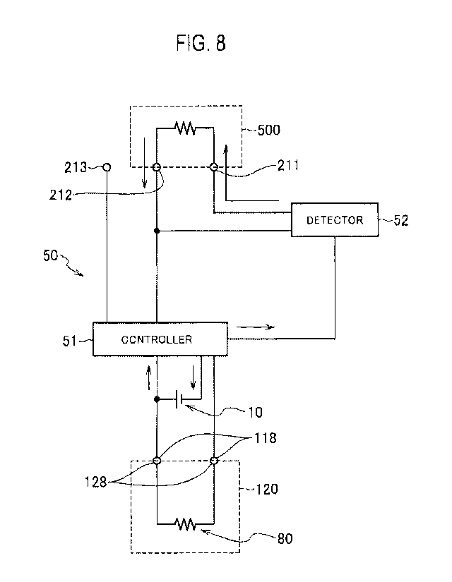
Fig. 8 is a schematic diagram of the flow of a current when the first
electrode
211 and the second electrode 212 are in conduction in the control circuit 50
according
to the first embodiment. For example, when an external element 500, such as a
finger
of the user, touches the first electrode 211 and the second electrode 212
simultaneously,
the first electrode 211 and the second electrode 212 are mutually in
conduction as
illustrated in Fig. 8. At this time, the power from the power supply 10 allows
a
predetermined current to flow between the first electrode 211 and the second
electrode
212. The predetermined current flows in the opposite direction to that of the
charging
current, at least at the second electrode 212. Note that Fig. 8 illustrates,
with an
arrow, the direction of the predetermined current when the first electrode 211
and the
second electrode 212 are in conduction.
[0086]
The control circuit 50 includes a detector 52 that detects the predetermined
current in the opposite direction to the direction of the current (charging
current)
flowing through the second electrode 212 when the charger 300 charges the
power
supply 10. The detector 52 may be disposed at a position into which no
charging
CA 03009050 2018-06-18
=
Deseription_JT-081PCT
current flows but the predetermined current in the opposite direction to the
direction of
the charging current flows. As a specific example, the detector 52 is disposed
at a
position at which the detector 52 couples the first electrode 211 and the
second
electrode 212 together. This arrangement enables the detector 52 to detect the
presence or absence of the predetermined current that flows between the first
electrode
211 and the second electrode 212. This arrangement enables the control circuit
50 to
determine whether the first electrode 211 and the second electrode 212 are
mutually in
conduction due to the external element. Therefore, the control circuit 50 can
detect
whether the user has touched the first electrode 211 and the second electrode
212
simultaneously.
[0087]
According to the present embodiment, when the detector 52 detects the
present or absence of the predetermined current that flows between the first
electrode
211 and the second electrode 212, the control circuit 50 detects the
conduction
between the first electrode 211 and the second electrode 212. However, the
detection
of the conduction between the first electrode 211 and the second electrode
212, is not
limited to this mode. For example, the control circuit 50 may be capable of
detecting
the difference between the direction of the current during charging and the
direction of
the current when the first electrode 211 and the second electrode 212 are in
conduction.
Even in this case, the control circuit 50 can detect whether the first
electrode 211 and
the second electrode 212 are mutually in conduction due to the external
element.
[0088]
The non-combustion-type flavor inhaler 100 may include display means for
notifying the user that the detector 52 has detected the predetermined
current. The
display means may be, for example, the light-emitting element 40 described
above.
The light-emitting mode of the light-emitting element 40 can notify the user
of the
detection of the predetermined current.
[0089]
The control circuit 50 performs predetermined control, on the basis of a
detected result of the predetermined current in the opposite direction to the
direction of
the current flowing through the second electrode 212 when the charger 300
charges the
power supply 10. For example, the control circuit 50 performs the
predetermined
control in response to the length of a period of the detection of the
predetermined
current. As an example, when the control circuit 50 has detected the
predetermined
current for several seconds, the control circuit 50 performs the predetermined
control.
21
CA 03009050 2018-06-18
=
Description_JT-081PCT
Note that, when the control circuit 50 has continuously detected the
predetermined
current for a predetermined time (first threshold value) or more, the control
circuit 50
favorably cancels the predetermined control. For example, when the control
circuit
50 has continuously detected the predetermined current for a time of the first
threshold
value or more while the light-emitting element 40 is reporting information as
the
predetermined control, the control circuit 50 cancels the report of the
information of
the light-emitting element 40. When the control circuit 50 has continuously
detected
the predetermined current for a time of the first threshold value or more
during
performance of user authentication or switching control between modes to be
used, as
the predetermined control, the control is canceled.
[0090]
Alternatively, the control circuit 50 may perform the predetermined control
when the control circuit 50 has detected the predetermined current a plurality
of times
within a predetermined period (second threshold value). For example, when the
control circuit 50 has detected the predetermined current three times for
several
seconds, the control circuit 50 performs the predetermined control.
[0091]
When the control circuit 50 detects the predetermined current generated by
the external element 500 different from the constituent elements of the non-
combustion-type flavor inhaler 100, the control circuit 50 may perform the
predetermined control, on the basis of the level of an electric resistance
value of the
external element 500. The detection of the electric resistance value of the
external
element 500 enables the control circuit 50 to distinguish whether the external
element
500 is a person's finger or a different object. For example, in a case where
the
electric resistance value of the external element is less than 100 0,
preferably less than
SI, the control circuit 50 may determine that the external element 500 is not
the
person's finger, not to perform the predetermined control. The control circuit
50 may
be capable of directly detecting the electric resistance value of the external
element
that brings the first electrode 211 and the second electrode 212 into
conduction.
Instead of this, the control circuit 50 may be capable of detecting a current
value and a
voltage value to estimate the electric resistance value of the external
element from the
detected current value and the detected voltage value. The detection or
estimation of
the electric resistance value of the external element by the control circuit
50, enables
the predetermined control not to be performed for an operation by a different
external
element having a lower electric resistance value than that of the person's
finger.
22
CA 03009050 2018-06-18
Description_IT-081PCT
[0092]
Furthermore, the control circuit 50 detects whether the power supply 10 is
being charged, and the control circuit 50 preferably does not perform, when
detecting
the charging of the power supply 10, the predetermined control regardless of
the
detected result of the predetermined current.
[0093]
The predetermined control may include determining whether the user is an
authorized user. Alternatively, in a case where a plurality of operation modes
is
provided as the operation mode of the non-combustion-type flavor inhaler 100,
the
predetermined control may include switching between the operation modes. The
switching between the operation modes is, for example, switching between a
sleep
mode in which the atomization control of atomizing the aerosol source is not
allowed
(power-saving mode) and a ready mode in which the aerosol source is allowed to
be
atomized. Alternatively, the switching between the operation modes is
switching of
the intensity of power supply output to the atomizer 80 (the absolute value or
duty
cycle of the power supply output). Alternatively, in a case where the non-
combustion-type flavor inhaler 100 includes a communication module, the
switching
between the operation modes is switching of whether communication with the
communication module is allowed. Alternatively, the predetermined control may
be
reset control of a value counted by the controller 51 (e.g., the accumulated
number of
puff actions, the accumulated number of puff actions in an one-time puff-
action series,
or the accumulated number of puff-action series). Note that the puff-action
series
means a series of actions in which the inhalation action is repeated
predetermined
times. Alternatively, the predetermined control may include providing, in the
light-
emitting mode of the light-emitting element 40, notification of a value
managed by the
controller 51 (e.g., the accumulated number of puff actions, the accumulated
number
of puff actions in an one-time puff-action series, the accumulated number of
puff-
action series, the remaining quantity of the power supply 10, the remaining
quantity of
the aerosol source, or whether the communication with the communication module
is
ready to perform).
[0094]
According to the first embodiment, the charger 300 supplies the charging
current to the power supply 10 through the second electrode 212 and the third
electrode 213. Instead of this, the charger 300 may supply the charging
current to the
power supply 10 through the first electrode 211 and the third electrode 213.
In this
23
CA 03009050 2018-06-18
=
Description JT-08 I PCT
case, the second electrode 212 is an electrode that does not contribute to
supply of the
charging current supplied from the charger 300 to the power supply 10. In this
manner, the charging current from the charger 300 to the power supply 10 is
required
at least to be supplied to the power supply assembly 110 through the third
electrode
213 and only one of the first electrode 211 and the second electrode 212.
[0095]
[Second Embodiment]
A non-combustion-type flavor inhaler 100A according to a second
embodiment will be described below. Note that the same constituents as those
of the
non-combustion-type flavor inhaler according to the first embodiment, are
denoted
with the same reference signs, and thus the descriptions thereof will be
omitted.
Differences from the first embodiment will be mainly described below.
[0096]
Fig. 9 is a view of the non-combustion-type flavor inhaler 100A according to
the second embodiment. Fig. 10 is a plan view of a power supply assembly
viewed
in the direction of an arrow 10A of Fig. 9. According to the second
embodiment, the
power supply assembly 110 includes a first electrode 211 and a second
electrode 212.
It should be noted that the first electrode 211 and the second electrode 212
are not to
be connected with paired electrodes 128 of an atomization assembly 120.
According
to the second embodiment, the third electrode 213 indicated in the first
embodiment is
not provided. According to the second embodiment, both of the first electrode
211
and the second electrode 212 are to be electrically connected with paired
electrodes
332 of a charger 300.
[0097]
The first electrode 211 and the second electrode 212 may be provided at any
positions of a first case 110X. The first electrode 211 and the second
electrode 212
are preferably provided in an end region of a non-mouthpiece end E2 of the
first case
110X.
[0098]
According to the second embodiment, an exposed portion of the first electrode
211 is positioned on a face facing a longitudinal direction A on the non-
mouthpiece
end E2 side of the first case 110X. An exposed portion of the second electrode
212 is
positioned on a face facing the longitudinal direction A on the non-mouthpiece
end E2
side of the first case 110X. The end face on the non-mouthpiece end E2 side in
the
longitudinal direction A of the exposed portion of the first electrode 211,
protrudes
24
CA 03009050 2018-06-18
Description_JT-081PCT
more than the end face on the non-mouthpiece end E2 side in the longitudinal
direction
A of the exposed portion of the second electrode 212. That is the exposed
portion of
the first electrode 211 and the exposed portion of the second electrode 212
are
provided on the faces facing the same direction in the first case 110X, and
there is a
difference in level between the end face of the exposed portion of the first
electrode
211 and the end face of the exposed portion of the second electrode 212. This
arrangement can inhibit an electric conductor, such as a metallic piece or a
metallic
plate, from conducting unexpectedly between the respective exposed portions of
the
first electrode 211 and the second electrode 212. From this viewpoint, the
difference
in level between the first electrode 211 and the second electrode 212 is
preferably 0.5
mm or more.
[0099]
Furthermore, the difference in level between the first electrode 211 and the
second electrode 212, is so sufficient that a finger of a user can make
conduction easily
between the first electrode 211 and the second electrode 212. Specifically,
the
difference in level is preferably 5 mm or less, more preferably 3 mm or less,
and even
more preferably 1 mm or less. Note that, instead of the example illustrated in
Fig. 9,
the difference in level may be formed such that the end face on the non-
mouthpiece
end E2 side in the longitudinal direction A of the exposed portion of the
second
electrode 212, protrudes more than the end face on the non-mouthpiece end E2
side in
the longitudinal direction A of the exposed portion of the first electrode
211.
[0100]
Next, the details of a control circuit 50 according to the second embodiment
will be described. Fig. 11 is a schematic diagram of the control circuit
according to
the second embodiment. The control circuit 50 includes a controller 51 for at
least
controlling power from a power supply 10 to an atomizer 80. A detector 52 is
provided between an electric wire extending from the first electrode 211 and
an
electric wire extending from the second electrode 212.
[0101]
Fig. 12 illustrates the flow of a current during charging in the control
circuit
50. According to the second embodiment, when the non-combustion-type flavor
inhaler 100 is inserted into a holder 320 of the charger 300, the first
electrode 211 and
the second electrode 212 of the power supply assembly 110 are electrically
connected
with the paired electrodes 332 on the charger 300 side. The charger 300
supplies a
charging current to the power supply 10 of the power supply assembly 110
through the
CA 03009050 2018-06-18
Description_JT-081PCT
first electrode 211 and the second electrode 212. This arrangement can charge
the
power supply 10. Note that Fig. 12 illustrates, with an arrow, the direction
of the
flow of the current during charging.
[0102]
According to the second embodiment, the control circuit 50 includes a
rectifying element 54 that inhibits the charging current from flowing in the
detector 52
when the charger 300 charges the power supply 10. The rectifying element 54
has an
anode 55 and a cathode 56. The anode 55 is electrically connected with the
detector
52. The cathode 56 is electrically connected with an electrode positive during
the
charging by the charger 300, from the first electrode 211 and the second
electrode 212.
This arrangement can prevent a large current during the charging from flowing
in the
detector 52.
[0103]
Fig. 13 is a schematic diagram of the flow of a current when the first
electrode
211 and the second electrode 212 are in conduction in the control circuit 50
according
to the second embodiment. For example, when an external element 500, such as a
finger of the user, touches the first electrode 211 and the second electrode
212
simultaneously, the first electrode 211 and the second electrode 212 are
mutually in
conduction as illustrated in Fig. 8. At this time, the power from the power
supply 10
allows a predetermined current to flow between the first electrode 211 and the
second
electrode 212. The predetermined current flows in the opposite direction to
that of
the charging current, at the first electrode 211 and the second electrode 212.
Note
that Fig. 13 illustrates, with an arrow, the direction of the predetermined
current when
the first electrode 211 and the second electrode 212 are in conduction.
[0104]
The control circuit 50 includes the detector 52 that detects the predetermined
current in the opposite direction to the direction of the current (charging
current)
flowing through the second electrode 212 when the charger 300 charges the
power
supply 10, similarly to the first embodiment. The detector 52 may detect the
presence or absence of the predetermined current that flows between the first
electrode
211 and the second electrode 212. Instead of this, the detector 52 may be
capable of
detecting the difference between the direction of the current during charging
and the
direction of the current when the first electrode 211 and the second electrode
212 are
in conduction. The detector 52 detects the predetermined current in the
opposite
direction to that of the charging current, so that the conduction between the
first
26
CA 03009050 2018-06-18
Description_JT-081PCT
electrode 211 and the second electrode 212 can be detected. This arrangement
can
detect whether the user has touched the first electrode 211 and the second
electrode
212 simultaneously.
[0105]
[Third Embodiment]
A non-combustion-type flavor inhaler according to a third embodiment will be
described below. Note that the same constituents as those of the non-
combustion-
type flavor inhaler according to the second embodiment, are denoted with the
same
reference signs, and thus the descriptions thereof will be omitted.
Differences from
the second embodiment will be mainly described below.
[0106]
Fig. 14 is a schematic diagram of a control circuit according the third
embodiment. Fig. 15 is a schematic diagram of the flow of a current during
charging
in the control circuit according to the third embodiment. Fig. 16 is a
schematic
diagram of the flow of a current when a first electrode and a second electrode
are in
conduction in the control circuit according to the third embodiment.
[0107]
The control circuit 50 includes: a controller 51 for at least controlling
power
from a power supply 10 to an atomizer 80; and a detector 52 that detects a
predetermined current in the opposite direction to that of a charging current.
A
rectifying element 54 is electrically connected with an electric wire
extending from the
first electrode 211 and an electric wire extending from the second electrode
212
through the controller 51 and the detector 52. The rectifying element 54 has
an anode
55 and a cathode 56. The anode 55 is electrically connected with the detector
52.
The cathode 56 is electrically connected with an electrode positive during
charging by
a charger 300, from the first electrode 211 and the second electrode 212. This
arrangement can prevent a large current during the charging from flowing in
the
detector 52.
[0108]
According to the third embodiment, the detector 52 can detect the
predetermined current in the opposite direction to the direction of the
current (charging
current) flowing through the second electrode 212 when the charger 300 charges
the
power supply 10.
[0109]
According to the third embodiment, the controller 51 and the detector 52 are
27
CA 03009050 2018-06-18
Description_JT-081PCT
mechanically disposed at the same location. Therefore, the controller 51 and
the
detector 52 are implementable on the same substrate, and thus are advantageous
to
miniaturization of the control circuit.
[0110]
[Fourth Embodiment]
A non-combustion-type flavor inhalation system according to a fourth
embodiment will be described below. Note that the same constituents as those
of the
non-combustion-type flavor inhalation system according to the first
embodiment, are
denoted with the same reference signs, and thus the description there of will
be
omitted. Differences from the first embodiment will be mainly described below.
[0111]
According to the fourth embodiment, the configuration of a non-combustion-
type flavor inhaler 100 is the same as that of the non-combustion-type flavor
inhaler
100 according to the first embodiment. According to the fourth embodiment, the
configuration of a charger 300 is different from that according to the first
embodiment.
[0112]
Fig. 17 is a schematic diagram of the flow of a current during charging in a
control circuit according to the fourth embodiment. Fig. 18 is a schematic
diagram of
the flow of a current when a first electrode and a second electrode are in
conduction in
the control circuit according to the fourth embodiment. The configuration of
the
control circuit 50 of the non-combustion-type flavor inhaler 100 is similar to
that
according to the first embodiment.
[0113]
The charger 300 includes a different electrode 333 in addition to paired
electrodes 332 for charging. When the non-combustion-type flavor inhaler 100
is
inserted into a holder of the charger 300, the second electrode 212 and a
third electrode
213 of a power supply assembly 110 are electrically connected with the paired
electrodes 332 for charging. Meanwhile, the first electrode 211 that does not
contribute to charging, is electrically connected with the electrode 333 of
the charger
300.
[0114]
According to the fourth embodiment, the charger 300 includes switching
means 350 capable of switching one of the paired electrodes 332 for charging
and the
electrode 333 between a conduction state and a non-conduction state. The
switching
means 350 can adopt, for example, a switch. The switch is switchable with, for
28
CA 03009050 2018-06-18
Description_JT-081PCT
example, a push button provided to a case 310 of the charger 300.
[0115]
As illustrated in Fig. 17, during charging, the one of the paired electrodes
332
for charging and the electrode 333 are in the non-conduction state. A
secondary
battery 330 of the charger is electrically connected with the second electrode
212 and
the third electrode 213 through the second electrode 212 and the third
electrode 213.
Therefore, the power supply 10 can be charged.
[0116]
For example, pressing the push button provided to the charger 300 allows the
one of the paired electrodes 332 for charging and the electrode 333 to be
switched to
the conduction state. This arrangement allows the first electrode 211 and the
second
electrode 212 to be switched into conduction, as illustrated in Fig. 18. At
this time, a
predetermined current in the opposite direction to that of a charging current,
flows at
least at the second electrode 212, similarly to the first embodiment. A
detector 52 of
the control circuit 50 can detect the predetermined current in the opposite
direction to
that of the charging current. This arrangement can detect the conduction
between the
first electrode 211 and the second electrode 212, with the charger 300. The
detection
of the conduction between the first electrode 211 and the second electrode 212
can be
used for user authentication or mode switching operation, as described in the
first
embodiment.
[0117]
As illustrated in Fig. 18, when the first electrode 211 and the second
electrode
212 are in conduction, the secondary battery 330 of the charger is out of
conduction
with the power supply 10. This arrangement cancels the charging to the power
supply 10 with the first electrode 211 and the second electrode 212 in
conduction.
[0118]
[Fifth Embodiment]
A non-combustion-type flavor inhaler according to a fifth embodiment will be
described below. Note that the same constituents as those of the non-
combustion-
type flavor inhaler according to the first embodiment, are denoted with the
same
reference signs, and thus the descriptions thereof will be omitted.
Differences from
the first embodiment will be mainly described below.
[0119]
Fig. 19 is a view of the non-combustion-type flavor inhaler according to the
fifth embodiment. Fig. 20 is a plan view of a power supply assembly viewed in
the
29
CA 03009050 2018-06-18
Description_JT-081PCT
direction of an arrow 20A of Fig. 19. The fifth embodiment is different from
the first
embodiment regarding the position of an opening 214 provided to the power
supply
assembly 110, the opening 214 being in communication with the atmosphere.
Specifically, the opening 214 is provided to the end face on the non-
mouthpiece end
E2 side of a first case 110X instead of the lateral face of the first case
110X. More
specifically, an insulating member 215 insulating a second electrode 212 and a
third
electrode 213, has the opening 214 formed.
[0120]
According to the present embodiment, the non-combustion-type flavor inhaler
may include the sensor 20 described in the first embodiment. The sensor 20 can
detect an inhalation action of a user.
[0121]
According to the present embodiment, the opening 214 in communication
with a second cavity 106 is provided to the end face on the non-mouthpiece end
E2
side of the first case 110X. Thus, at the same time a finger of the user is
put onto the
second electrode 212 at a recess position on the end face on the non-
mouthpiece end
E2 side of the first case 110X, the finger of the user blocks the opening 214.
The
block causes an air flow, so that the internal pressure of the second cavity
106 rises.
In other words, the sensor 20 can detect an action in which the user touches
the second
electrode 212.
[0122]
When a control circuit 50 detects a predetermined current in the opposite
direction to the direction of a current flowing through the second electrode
212 when
the charger 300 charges a power supply 10 and additionally the sensor 20
detects the
action in which the user touches the second electrode 212, the control circuit
50 may
perform the predetermined control described above.
[0123]
[Other Embodiments]
The present invention has been described in the embodiments, but it should
not be understood that the invention is limited to the descriptions and the
drawings
included in part of this disclosure. The disclosure clarifies various
alternative
embodiments, examples, and investment techniques, for persons skilled in the
art.
[0124]
For example, the rectifying element 54 described in the second embodiment
may be applied to the control circuit 50 according to the first embodiment.
CA 03009050 2018-06-18
Deseription_JT-081PCT
[0125]
The embodiment has exemplified the tobacco source 131 as a flavor source.
However, the embodiment is not limited to this. The flavor source does not
necessarily contain tobacco material. Furthermore, the non-combustion-type
flavor
inhaler 100 does not necessarily include the flavor source, but an inhalant
flavor
ingredient may be added to the aerosol source.
[0126]
The embodiment has exemplified that the reservoir 60 that stores the aerosol
source is the porous body. However, the embodiment is not limited to this. The
reservoir 60 may be a tank that houses a liquid aerosol source.
[0127]
The embodiment has exemplified that the non-combustion-type flavor inhaler
100 includes the capsule unit 130. However, the embodiment is not limited to
this.
For example, the non-combustion-type flavor inhaler 100 may include a
cartridge
including a flavor source.
[0128]
According to the embodiment, at least one of the first electrode 211 and the
second electrode 212 is electrically connectable to the charger 300 for
charging the
power supply 10. In addition to this, the first paired electrodes 118 of the
power
supply assembly 110, namely, the paired electrodes for electrical connection
with the
atomizer 80 may be electrically connectable to the charger 300.
[0129]
According to the embodiment, the power supply assembly 110 and the
atomization assembly 120 are capable of screwing mutually with the spiral
groove and
the spiral protrusion. However, the embodiment is not limited to this.
Engagement
between a claw rib formed on the first case 110X of the power supply assembly
110
and a recess formed on the second case 120X of the atomization assembly 120
may
enable the power supply assembly 110 and the atomization assembly 120 to
engage
with each other.
[0130]
According to the embodiment, the atomizer 80 is controlled on the basis of the
output value of the sensor 20 that detects the inhalation action of the user.
Instead of
this, pressing of a push button by the user may allow the atomizer 80 to be
controlled,
namely, the aerosol source to be atomized.
[0131]
31
CA 03009050 2018-06-18
Description_JT-081PCT
A mouthpiece to be held in the user' mouth, may be detachably attached on
the mouthpiece end El side of the atomization assembly 120. Instead of this,
the
mouthpiece may be integrally formed with the atomization assembly 120. In this
case, the mouthpiece and the atomization assembly 120 are to be replaced as
one set.
32