Note: Descriptions are shown in the official language in which they were submitted.
CA 03009122 2018-06-19
WO 2017/109159
PCT/EP2016/082524
1
Power generation using liquids with different vapour pressures
The present disclosure relates to apparatus and methods of generating power
that utilise the flow of
vapour between two or more liquid bodies having different vapour pressures.
Power is generated as
a result of the flow of vapour from a liquid body having a higher vapour
pressure to a liquid body
having a lower vapour pressure.
Energy is released when two liquids of different salinities mix together. For
example, the osmotic
pressure difference between fresh water and sea water is approximately 29 atm
at 20 C. For a flow
rate of 1 m3/s this represents a theoretical power of almost 3 MW. This
release of energy may
therefore be used to generate power, for example at the mouth of a river as it
enters the sea.
Most methods of extracting this energy rely on osmosis of water across semi-
permeable
membranes. One such method is pressure-retarded osmosis (PRO). In PRO a saline
solution is
contained within a pressure chamber and separated from fresh water by a semi-
permeable
membrane. The semi-permeable membrane is permeable to water but impermeable to
the dissolved
salt ions (Na + and 01-). The passage of water across the semi-permeable
membrane from the fresh
water side to the saline side causes the pressure in the chamber to increase.
This pressure increase
is then used to generate power, for example by releasing the pressure through
a turbine to generate
electricity.
Another method of generating power from salinity gradients is reverse
electrodialysis. In reverse
electrodialysis a saline solution and fresh water are passed through ion-
exchange membranes. The
chemical potential difference between the saline solution and fresh water
generates a voltage across
the membranes, thus providing power.
Both of these methods rely on the use of semi-permeable membranes and suffer
from numerous
drawbacks as a result. The disadvantages of using semi-permeable membranes
include their high
cost, their vulnerability to fouling, degradation, polarisation, the
substantial head loss that occurs
when a liquid passes through a membrane, and the requirement to filter and pre-
treat the solutions.
An alternative method for generating power from salinity gradients is to use
the free surface of the
liquids themselves as the membrane. Since a saline solution has a lower vapour
pressure than that
of fresh water, water vapour will be transferred from fresh water to a saline
solution in a sealed
chamber. In Salinity Gradient Power: Utilizing Vapor Pressure Differences,
Science, 206, 452-454
(1979) and Salinity-Gradient Vapor-Pressure Power Conversion, Energy, 7(3),
237-246 (1982)
arrangements are described in which a turbine is interposed in the vapour flow
between fresh water
CA 03009122 2018-06-19
WO 2017/109159
PCT/EP2016/082524
2
and a saline solution in an evacuated chamber, and it is suggested that the
flow of vapour through
the turbine could be used to generate power. In these arrangements the
evaporation and
condensation of the vapour causes a transfer of heat from the fresh water to
the saline solution. It is
therefore necessary to transfer heat back from the saline solution to the
fresh water solution,
otherwise the rate of vaporisation will reduce and eventually stop.
Although the vapour pressure methods outlined above overcome some of the
disadvantages of using
semi-permeable membranes, other drawbacks are associated with using such an
approach. One
disadvantage of these arrangements is that it is necessary for the atmosphere
to be evacuated
initially from the chamber to provide a vacuum in order that the flow of
vapour may drive a turbine
placed in the vapour flow. This requires an additional input of energy into
the system and also
requires that the liquid bodies are degassed to avoid outgassing into the
evacuated chamber.
Another disadvantage of this prior art arrangement is that the pressure drop
across the turbine is
likely to be very small, approximately 0.4 mmHg, when vapour is transferred
between fresh water
and sea water at 20 C. This makes power extraction using a gas turbine
impractical. The absolute
pressure of the vapour is also low, approximately 18 mmHg at 20 C, which means
that the force
acting on the turbine is low, thereby hindering the amount of power that can
be generated by the
turbine.
It is an object of the present disclosure to provide improved apparatus and
methods for generating
power that utilise the flow of vapour between two or more liquid bodies having
different vapour
pressures.
According to a first aspect of the present disclosure, there is provided a
method of generating power
comprising:
transferring liquid via the vapour phase from a source liquid body to a sink
liquid body, and
generating power by releasing liquid from the sink liquid body,
wherein the vapour pressure of the source liquid body is higher than the
vapour pressure of the
sink liquid body, and
wherein the source liquid body and the sink liquid body are not in physical
contact.
In this way, power is generated as a result of the flow of vapour from a
liquid body having a higher
vapour pressure to a liquid body having a lower vapour pressure but without
the need for semi-
permeable membranes.
CA 03009122 2018-06-19
WO 2017/109159
PCT/EP2016/082524
3
The transfer of liquid via the vapour phase from the source liquid body to the
sink liquid body may
cause a hydrostatic pressure to build up in the sink liquid body. The maximum
possible hydrostatic
head that could be achieved using this method is about 300 m. However, the
apparatus may be
operated in such a way that a hydrostatic head of less than this height is
achieved, for example 100
m or less.
The step of generating power may comprise passing the liquid released from the
sink liquid body
through a first mechanism for generating power. Typically, a build-up of
hydrostatic pressure in the
sink liquid body can be used to force liquid out through the first mechanism
for generating power.
Typically, the first mechanism for generating power is a turbine, preferably a
water turbine.
Alternative mechanisms for generating power are also contemplated, for example
those employing
pistons, screws or paddles.
Alternatively, the release of liquid from the sink liquid body may cause the
sink liquid body to rotate
about an axis of rotation, wherein the axis of rotation is not coincident with
any part of the sink liquid
body, and wherein power is generated by the rotation of the sink liquid body.
In this way, the axis of
rotation is spaced apart from the sink liquid body.
Preferably, in methods wherein the sink liquid body rotates about an axis of
rotation, power is
generated using an electrical alternator or generator.
In methods wherein the sink liquid body rotates about an axis of rotation, the
axis of rotation may be
coincident with at least part of the source liquid body. Alternatively, the
axis of rotation may be spaced
apart from the source liquid body such that it is not coincident with any part
of the source liquid body,
and the release of liquid from the sink liquid body may cause the source
liquid body to rotate about
the axis of rotation. In methods wherein the axis of rotation is not
coincident with any part of the
source liquid body, the closest distance between the source liquid body and
the axis of rotation is
preferably greater than the closest distance between the sink liquid body and
the axis of rotation.
The method of the first aspect may comprise a further step of generating power
by passing vapour
from the source liquid body through a second mechanism for generating power
during the step of
transferring liquid via the vapour phase from the source liquid body to the
sink liquid body. The
second mechanism for generating power may be a turbine, preferably a gas
turbine. Alternative
mechanisms for generating power are also contemplated, for example those
employing pistons,
screws or paddles.
Preferably a heat pump is used to transfer heat from the sink liquid body to
the source liquid body.
Evaporation from the source liquid body and condensation of the vapour in the
sink liquid body may
CA 03009122 2018-06-19
WO 2017/109159
PCT/EP2016/082524
4
cause a transfer of heat from the source liquid body to the sink liquid body.
This transfer of heat
may cause the difference between the vapour pressures of the source liquid
body and the sink liquid
body to reduce. A reduction in the vapour pressure gradient between the source
liquid body and the
sink liquid body will have the effect of reducing the rate of vapour transfer,
and may eventually halt
vapour transfer completely. It is therefore desirable to transfer heat back
from the sink liquid body
to the source liquid body. This may be achieved by using a heat pump.
Alternatively or additionally,
heat may be transferred from the sink liquid body to the source liquid body
using a heat exchanger.
The difference between the vapour pressure of the source liquid body and the
vapour pressure of
the sink liquid body may be caused or increased by increasing the temperature
of the source liquid
body, by lowering the temperature of the sink liquid body, or, preferably, by
a combination of the two.
This may be achieved through the use of a heat pump, which transfers heat from
the sink liquid body
to the source liquid body, such that T1 > Tz, where T1 is the temperature of
the source liquid body
and T2 is the temperature of the sink liquid body. The use of a heat pump is
advantageous in this
situation as the difference between Ti and T2 is not large and the transfer of
heat will therefore be
efficient. Alternatively or additionally, the source liquid body may be heated
by other means, for
example using solar energy, electrical energy, or combustion.
According to a second aspect of the present disclosure, there is provided a
method of generating
power comprising:
transferring liquid via the vapour phase from a source liquid body to a sink
liquid body, and
generating power by passing vapour from the source liquid body through a
mechanism for
generating power as it is transferred from the source liquid body to the sink
liquid body,
wherein a heat pump is used to transfer heat from the sink liquid body to the
source liquid
body,
wherein the vapour pressure of the source liquid body is higher than the
vapour pressure of
the sink liquid body, and
wherein the source liquid body and the sink liquid body are not in physical
contact.
In the method of the second aspect, the mechanism for generating power may be
a turbine,
preferably a gas turbine. Alternative mechanisms for generating power are also
contemplated, for
example those employing pistons, screws or paddles.
The difference between the vapour pressure of the source liquid body and the
vapour pressure of
the sink liquid body is increased by increasing the temperature of the source
liquid body, by lowering
the temperature of the sink liquid body, or, preferably, by a combination of
the two. This is achieved
through the use of the heat pump, which transfers heat from the sink liquid
body to the source liquid
CA 03009122 2018-06-19
WO 2017/109159
PCT/EP2016/082524
body, such that Ti > T2, where Ti is the temperature of the source liquid body
and T2 is the
temperature of the sink liquid body. The use of a heat pump is particularly
advantageous in situations
where the difference between Ti and T2 is not large and the transfer of heat
will therefore be efficient.
Alternatively, a large temperature difference between Ti and T2 may be caused
by the transfer of
5 heat from the sink liquid body to the source liquid body by the heat
pump, such that Ti >> T2. Ti
may be increased by any amount up to the boiling point of the source liquid.
For example, Ti may
be 10 C, 20 C, 30 C, 40 C, 50 C, 60 C or more higher than T2. This has the
advantage of causing
a more substantial difference between the vapour pressure of the source
chamber and the vapour
pressure of the sink chamber, which may make the generation of power using gas
turbines and other
means more practicable. The source liquid body may additionally be heated by
other means, for
example using solar energy, electrical energy, or combustion.
In any of the methods disclosed herein, there may be more than one source
liquid body.
Alternatively, or in addition, there may be more than one sink liquid body.
In all the methods disclosed herein, the vapour pressure of the source liquid
body is higher than the
vapour pressure of the sink liquid body. This has the effect of providing a
vapour pressure gradient
between the source liquid body and the sink liquid body, wherein the vapour
pressure above the
source liquid body is higher than the vapour pressure above the sink liquid
body. This vapour
pressure gradient causes a transfer of vapour (also described as a "flow of
vapour") from the source
liquid body to the sink liquid body, where it condenses. A greater difference
between the vapour
pressures of the source liquid body and the sink liquid body will result in a
faster rate of transfer of
liquid from the source liquid body to the sink liquid body.
In any of the methods described herein, the source liquid body and the sink
liquid body may be
aqueous solutions. Preferably, the source liquid body has a different salinity
to the sink liquid body.
More preferably, the source liquid body has a lower salinity than the sink
liquid body. The source
liquid body may be obtained from a fresh water body and the sink liquid body
may be obtained from
a saline body. For example, the fresh water body may be a river or a fresh
water lake and the saline
body may be a sea, an ocean or a lake having a higher salinity than a fresh
water lake.
In any of the methods described herein, there may comprise a further step of
increasing the salinity
of the sink liquid body by adding a salt. The step of adding a salt to the
sink liquid body has an
advantage of increasing the difference between the vapour pressures of the
source liquid body and
the sink liquid body. Preferably, the salt is sodium chloride.
CA 03009122 2018-06-19
WO 2017/109159
PCT/EP2016/082524
6
In any of the methods described herein, the source liquid body and the sink
liquid body may be in
thermal contact.
In any of the methods described herein, the source liquid body, the sink
liquid body, and the vapour
phase may be contained essentially within at least one chamber. The at least
one chamber may be
sealable so that it may be isolated from the surrounding atmosphere. The
pressure that exists within
the chamber may be controlled.
In arrangements where the chamber is sealable, the method may further comprise
the step of
evacuating the atmosphere from within the at least one chamber prior to the
generation of power.
Preferably, when the chamber is evacuated, the method further comprises the
step of degassing at
least one of the source liquid body and the sink liquid body. Degassing of the
source liquid body and
the sink liquid body may be performed either before or after the liquids have
entered the chamber.
Preferably, the atmosphere within the chamber is evacuated to leave
substantially only vapour from
the source liquid body and/or the sink liquid body in the gas phase within the
apparatus or chamber.
This has an advantage of increasing the speed of vapour flow from the source
liquid body to the sink
liquid body, but requires an additional input of energy in order to evacuate
the chamber. Preferably,
when the method is carried out in a sealable chamber, in which the chamber can
be isolated from
the surrounding atmosphere, the method comprises a single step of evacuating
the atmosphere from
the chamber because the airtight nature of the chamber is able to prevent the
return of atmospheric
gas. Where the chamber is not completely airtight or where degassing from the
liquids occurs,
multiple steps of evacuating the atmosphere from the chamber may be required.
In any of the methods described herein, the sink liquid body may have a volume
that is substantially
greater than the volume of the source liquid body. Preferably, the sink liquid
body has a large enough
volume such that the transfer of liquid from the source liquid body to the
sink liquid body via the
vapour phase does not reduce appreciably the difference between the vapour
pressures of the
source liquid body and the sink liquid body to a level where the rate of
vapour transfer is substantially
reduced. For example, in aspects wherein the sink liquid body is a saline
solution and the source
liquid body is a saline solution having a lower salinity than that of the sink
liquid body, such as fresh
water, the transfer of liquid from the source liquid body to the sink liquid
body via the vapour phase
will progressively reduce the salinity of the sink liquid body. Such a
reduction in the salinity of the
sink liquid body will reduce the difference between the vapour pressures of
the source liquid body
and the sink liquid body to a level where the rate of vapour transfer is
reduced, and potentially
eventually halted.
CA 03009122 2018-06-19
WO 2017/109159
PCT/EP2016/082524
7
In any of the methods described herein, the step of generating power by
releasing liquid from the
sink liquid body may occur once during the method. Alternatively, the step of
generating power by
releasing liquid from the sink liquid body may be repeated multiple times.
Preferably, the step of
generating power by releasing liquid from the sink liquid body occurs
cyclically. Alternatively, the
step of generating power by releasing liquid from the sink liquid body occurs
essentially continuously
during the method.
According to a third aspect of the present disclosure, there is provided an
apparatus for generating
power comprising a source chamber and a sink chamber,
wherein:
the source chamber and the sink chamber are connected by a vapour flow
opening;
the source chamber comprises an opening for connecting to a first liquid
source;
the sink chamber comprises an opening for connecting to a second liquid
source;
the sink chamber opening is sealable;
the source chamber and the sink chamber are configured so that a liquid
contained within
the source chamber and a liquid contained within the sink chamber are
physically separated;
and
the apparatus comprises a first mechanism for generating power from a flow of
liquid through
the sink chamber opening.
The apparatus comprises a mechanism for sealing the sink chamber opening.
Preferably, the
mechanism for sealing the sink chamber opening comprises or consists of a
valve. The valve may
comprise a cylinder or a piston.
The first mechanism for generating power may be a turbine, preferably a water
turbine. Alternative
mechanisms for generating power are also contemplated, for example those
employing pistons,
screws or paddles.
The apparatus may further comprise a second mechanism for generating power
from a flow of
vapour through the vapour flow opening. The second mechanism for generating
power may be a
turbine, preferably a gas turbine. Alternative mechanisms for generating power
are also
contemplated, for example those employing pistons, screws or paddles.
The apparatus may comprise a heat pump configured to transfer heat from the
sink chamber to the
source chamber. As described above in relation to the methods of the present
disclosure, an
advantage of a heat pump is that it may enable the difference between the
vapour pressure of the
liquid in the source chamber and the vapour pressure of the liquid in the sink
chamber to be
CA 03009122 2018-06-19
WO 2017/109159
PCT/EP2016/082524
8
increased by increasing the temperature of the liquid in the source chamber
and/or by lowering the
temperature of the liquid in the sink, as described above in relation to the
methods of the present
disclosure. Alternatively, heat may be transferred from the sink liquid body
to the source liquid body
using a heat exchanger.
The apparatus may further comprise a pressure release valve configured so that
pressurised gas
may be released from the interior of the apparatus. The pressure release valve
may additionally
comprise a mechanism for generating power from the flow of vapour through the
pressure release
valve.
According to a fourth aspect of the present disclosure, there is provided an
apparatus for generating
power comprising a source chamber and a sink chamber,
wherein:
the source chamber and the sink chamber are connected by a vapour flow
opening;
the apparatus comprises a mechanism for generating power from the flow of
vapour through
the vapour flow opening;
the source chamber comprises an opening for connecting to a first liquid
source;
the sink chamber comprises an opening for connecting to a second liquid
source;
the source chamber and the sink chamber are configured so that a liquid
contained within
the source chamber and a liquid contained within the sink chamber are
physically separated;
and
the apparatus comprises a heat pump, which is configured to transfer heat from
the sink
chamber to the source chamber.
The mechanism for generating power may be a turbine, preferably a gas turbine.
Alternative
mechanisms for generating power are also contemplated, for example those
employing pistons,
screws or paddles.
In any of the apparatus of the third or fourth aspect of the disclosure, the
sink chamber may have a
volume that is substantially greater than the volume of the source chamber.
Preferably, the sink
chamber has a large enough volume such that transfer of liquid from the source
chamber to the sink
chamber via the vapour phase does not reduce the difference between the vapour
pressures of the
source liquid body and the sink liquid body to a level where the rate of
vapour transfer is substantially
reduced. For example, in aspects wherein the sink liquid body comprises a
saline solution and the
source liquid body comprises a saline solution having a lower salinity than
that of the sink liquid body,
such as fresh water, the transfer of liquid from the source chamber to the
sink chamber via the
vapour phase will progressively reduce the salinity of the liquid in the sink
chamber. Such a reduction
CA 03009122 2018-06-19
WO 2017/109159
PCT/EP2016/082524
9
in the salinity of the liquid in the sink chamber will reduce the difference
between the vapour
pressures of the liquid in the source chamber and the liquid in the sink
chamber to a level where the
rate of vapour transfer is reduced, and eventually halted.
In any of the apparatus of the third or fourth aspect of the disclosure, the
source chamber may be
sealable so that it may be isolated from the surrounding atmosphere.
In any of the apparatus of the third or fourth aspect of the disclosure, the
source chamber and the
sink chamber may be configured so that a liquid body contained within the
source chamber and a
liquid body contained within the sink chamber are in thermal contact.
According to a fifth aspect of the present disclosure, there is provided an
apparatus for generating
power comprising a chamber,
wherein:
the chamber comprises a source liquid portion and a sink liquid portion;
the sink liquid portion is rotatable about an axis of rotation;
the axis of rotation is not coincident with any part of the sink liquid
portion;
the sink liquid portion comprises an outlet;
the sink liquid portion outlet is positioned such that the release of liquid
through the sink liquid
portion outlet causes the sink liquid portion to rotate about the axis of
rotation;
the source liquid portion comprises an inlet for connecting to a first liquid
source;
the sink liquid portion comprises an inlet for connecting to a second liquid
source;
and
the apparatus comprises a first mechanism for generating power from the
rotation of the sink liquid
portion about the axis of rotation.
The first mechanism for generating power may be an electrical alternator or
generator.
The source liquid portion may be rotatable about the axis or rotation.
Typically, the chamber comprising the source liquid portion and the sink
liquid portion is rotatable
about the axis of rotation.
The source liquid portion and the sink liquid portion may be configured to
contain liquid when the
chamber rotates about the axis of rotation.
The sink liquid portion may be configured to contain liquid when the chamber
is not rotating about
the axis of rotation.
CA 03009122 2018-06-19
WO 2017/109159
PCT/EP2016/082524
The source liquid portion may be configured to contain liquid when the chamber
is not rotating about
the axis of rotation.
5 The chamber may comprise a first arm, wherein the first arm comprises a
distal end, wherein the
distal end is the end of the first arm that is furthest from the axis of
rotation, and wherein the sink
liquid portion is located at the distal end of the first arm.
The axis of rotation may be spaced apart from the source liquid portion such
that it is not coincident
10 with any part of the source liquid portion. In apparatus wherein the
axis of rotation is not coincident
with any part of the source liquid portion, the chamber may comprise a second
arm, wherein the
second arm comprises a distal end, wherein the distal end is the end of the
second arm that is
furthest from the axis of rotation, and wherein the source liquid portion is
located at the distal end of
the second arm. Additionally or alternatively, in apparatus wherein the axis
of rotation is not
coincident with any part of the source liquid portion, the closest distance
between the source liquid
portion and the axis of rotation is preferably greater than the closest
distance between the sink liquid
portion and the axis of rotation.
In arrangements where the chamber has a first arm comprising the sink liquid
portion and a second
arm comprising the source liquid portion, the arms may be configured such that
the first arm is not
parallel to the second arm. For example, the first arm or the second arm or
both the first arm and
the second arm may be configured such that when the chamber is not rotating,
the distal end of the
arm is located below the portion of the arm nearest the axis of rotation. The
first and second arms
may be arranged such that the first arm and the second arm are substantially
parallel when the
chamber rotates.
Alternatively, the axis of rotation may be coincident with at least part of
the source liquid portion.
Preferably, the apparatus further comprises a second mechanism for generating
power from a flow
of vapour between the source liquid portion and the sink liquid portion. The
second mechanism for
generating power may be a turbine, preferably a gas turbine. Alternative
mechanisms for generating
power are also contemplated, for example those employing pistons, screws or
paddles.
The apparatus may comprise a heat pump configured to transfer heat from the
sink liquid portion to
the source liquid portion.
CA 03009122 2018-06-19
WO 2017/109159
PCT/EP2016/082524
11
The apparatus may comprise a heat exchanger configured to transfer heat
between the sink liquid
portion and the source liquid portion.
The source liquid portion and the sink liquid portion may be configured so
that a liquid contained
within the source liquid portion and a liquid contained within the sink liquid
portion are physically
separated. Typically, separation of the liquid in the source liquid portion
from the liquid in the sink
liquid portion is achieved by rotation of the sink chamber about the axis of
rotation. However, the
primary function of the rotation of the chamber is to provide an increase in
pressure in the sink liquid
body, and other means of confining the liquid bodies contained within the
source liquid portion and
the sink liquid portion are contemplated that do not rely on the rotation of
the chamber but rely instead
on the configuration of the apparatus.
The source liquid portion and the sink liquid portion may be configured so
that a liquid body contained
within the source liquid portion and a liquid body contained within the sink
liquid portion are in thermal
contact.
In any of the apparatus described herein, the chamber may be sealable so that
it may be isolated
from the surrounding atmosphere. The apparatus may comprise a mechanism for
evacuating the
interior atmosphere of the apparatus.
The sink liquid portion may have a volume that is substantially greater than
the volume of the source
liquid portion. Preferably, the sink liquid portion has a large enough volume
such that transfer of
liquid from the source liquid portion to the sink liquid portion via the
vapour phase does not reduce
the difference between the vapour pressures of the source liquid body and the
sink liquid body to a
level where the rate of vapour transfer is substantially reduced. For example,
in aspects wherein the
sink liquid body comprises a saline solution and the source liquid body
comprises a saline solution
having a lower salinity than that of the sink liquid body, such as fresh
water, the transfer of liquid
from the source liquid portion to the sink liquid portion via the vapour phase
will progressively reduce
the salinity of the liquid in the sink liquid portion. Such a reduction in the
salinity of the liquid in the
sink liquid portion will reduce the difference between the vapour pressures of
the liquid in the source
liquid portion and the liquid in the sink liquid portion to a level where the
rate of vapour transfer is
reduced, and eventually halted.
In any of the apparatus described herein, the first liquid source and the
second liquid source may be
aqueous solutions. The first liquid source may have a different salinity to
the second liquid source.
Typically, the first liquid source has a lower salinity than the second liquid
source. The first liquid
source may be obtained from a fresh water body and the second liquid source
may be obtained from
CA 03009122 2018-06-19
WO 2017/109159
PCT/EP2016/082524
12
a saline body. For example, the fresh water body may be a river or a fresh
water lake and the saline
body may be a sea, an ocean or a lake having a higher salinity than a fresh
water lake.
The following features apply to each of the methods and apparatus described
herein.
The source liquid and/or the sink liquid may be treated prior to entering the
apparatus. Such
treatment may include filtering suspended solids and/or larger organisms from
the liquid.
The source liquid and/or the sink liquid may be heated to an elevated
temperature (above ambient
temperature). Heating of the source liquid is preferable in order to increase
the vapour pressure
differences between the source liquid and the sink liquid and thereby enhance
the rate of vapour
transfer.
In the aspects of the disclosure where the first liquid source is a fresh
water source, such as a river,
and the second liquid source is a saline solution, such as an ocean or a sea,
it may be advantageous
to construct a pipe or canal to carry the fresh water out to sea.
Alternatively or in addition, it may be
advantageous to bring undiluted sea water to the mouth of the river and to
generate power at the
terminus of the pipe or canal, thereby maximising the difference in salinity
between the fresh water
and the saline solution. It may also be advantageous to source the saline sink
liquid at depth.
Sourcing the saline sink liquid at depth would have the advantage that deep
water is less likely to be
diluted with fresh water and that deep water is usually cooler than surface
water, thereby enhancing
the vapour pressure differences between the sink liquid and the source liquid.
Since each of the methods and apparatus disclosed herein relies on the
evaporation and
condensation of vapour, it is preferred to increase the surface areas of the
liquids so as to increase
the rates of these processes. It is also preferred to increase the internal
surface area of the sink
chamber so that there is a greater surface area upon which the vapour may
condense.
In aspects of the disclosure where the atmosphere within the apparatus is not
evacuated, it is
advantageous for the apparatus to be completely airtight during operation, but
this is not a necessary
condition. While it may be advantageous for the apparatus to be entirely
airtight, a vapour pressure
gradient between the source liquid and the sink liquid within the apparatus
may still be maintained
even in the case of a limited exchange of gas between the interior atmosphere
of the apparatus and
the external atmosphere.
Features described herein in conjunction with a particular aspect or example
of the disclosure are
to be understood to be applicable to any other aspect, embodiment or example
described herein
CA 03009122 2018-06-19
WO 2017/109159
PCT/EP2016/082524
13
unless incompatible therewith. As used herein, the singular is understood to
include a plurality,
unless the context requires otherwise.
The term "comprising" encompasses "including" as well as "consisting" and
"consisting essentially
of" e.g. a composition "comprising" X may consist exclusively of X or may
include something
additional e.g. X + Y.
The term "aqueous solution" as used herein, in relation to any of the methods
or apparatus described,
includes fresh water.
The term "positive pressure" as used herein, in relation to any of the methods
or apparatus described,
means a pressure within a system that is greater than the environment that
surrounds that system.
The term "phase" as used herein, in relation to any of the methods or
apparatus described, means
a physically separate, homogeneous part of a heterogeneous system.
The term "source liquid" as used herein, in relation to any of the methods or
apparatus described,
includes a liquid that is contained within the first liquid source or that is
contained within the source
liquid chamber/portion/reservoir/body.
The term "sink liquid" as used herein, in relation to any of the methods or
apparatus described,
includes a liquid that is contained within the second liquid source or that is
contained within the sink
liquid chamber/portion/reservoir/body.
The term "source liquid body" as used herein, in relation to any of the
methods or apparatus
described, does not include any liquid contained within of flowing through
inlets, outlets, or other
openings used to supply or release liquid from the source liquid body.
The term "sink liquid body" as used herein, in relation to any of the methods
or apparatus described,
does not include any liquid contained within of flowing through inlets,
outlets, or other openings used
to supply or release liquid from the sink liquid body.
The term "closest distance" as used herein, in relation to any of the methods
or apparatus described,
means the distance between the parts closest in space of two bodies or
elements.
The disclosure is further illustrated by reference to the following drawings,
wherein:
CA 03009122 2018-06-19
WO 2017/109159
PCT/EP2016/082524
14
Figure 1 shows a schematic cross-sectional side view of a first apparatus
according to the present
disclosure;
Figure 2 shows a schematic cross-sectional side view of a second apparatus
according to the
present disclosure;
Figure 3 shows a schematic view looking down onto the second apparatus of
Figure 2;
Figure 4 shows a schematic cross-section side view of a third apparatus
according to the present
disclosure;
Figure 5 shows a schematic cross-sectional side view of a fourth apparatus
according to the present
disclosure; and
Figure 6 shows a schematic view looking down onto the fourth apparatus of
Figure 5.
With reference to Figure 1, there is illustrated an apparatus according to the
present disclosure. The
apparatus may be used in a method of the present disclosure, and may be
described as a
"gravitational method". The apparatus 10 comprises a source chamber 12 and a
sink chamber 14.
The source chamber 12 and the sink chamber 14 are connected by a vapour flow
opening 16. The
vapour flow opening 16 is located above the maximum level reached by liquid
within the apparatus
during operation, shown by line 18, such that liquid does not pass through the
vapour flow opening
during use of the apparatus.
The source chamber 12 incorporates an opening 20, through which a first liquid
22 (also described
herein as the "source liquid"), may pass to or from a first liquid source 24.
The sink chamber 14 incorporates an opening 26, through which a second liquid
28 (also described
herein as the "sink liquid"), may pass to or from a second liquid source 30.
The sink chamber opening 26 incorporates a valve 32, enabling the opening 26
to be closed or
sealed.
The sink chamber opening 26 also incorporates a first mechanism for generating
power 34, such as
a turbine, that may be used to generate power.
Source liquid 22 is separated from sink liquid 28, for example, by wall 60.
CA 03009122 2018-06-19
WO 2017/109159
PCT/EP2016/082524
Power may be generated as follows:
1) The source liquid 22 is introduced into the source chamber 12 from the
first liquid source 24
through the source chamber opening 20, and the sink liquid 28 is introduced
into the sink
5 chamber 14 from the second liquid source 30 through the sink chamber
opening 26.
2) The sink chamber opening valve 32 is closed.
3) Liquid is transferred via the vapour phase from the source liquid 22 in
the source chamber
12 to the sink liquid 28 in the sink chamber 14 due to the difference between
the vapour
pressures of the source liquid 22 and the sink liquid 28.
10 4) The transfer of liquid via the vapour phase in step 3 causes the
level of the sink liquid 28 in
the sink chamber 14 to rise, resulting in the build-up of a hydrostatic head
in the sink liquid
28 in the sink chamber 14.
5) The sink chamber opening valve 32 is opened.
6) The sink liquid 28 flows under a hydrostatic pressure through the sink
chamber opening 26
15 and the turbine 34, thereby generating power.
7) The process may be repeated from, and including, step 2 in a cyclical
manner.
The source chamber opening 20 may optionally incorporate a valve 36 such that
the opening may
be closed. Optionally, if present, the source chamber opening valve 36 may be
closed during step
2 of the above listed sequence.
In the case that the source chamber opening valve 36 is not closed during step
2, it is preferable that
the source chamber opening 20 is located entirely below the level (marked by
line 58) of the first
liquid source 24, such that gas may not pass into the apparatus 10 during
operation.
The apparatus 10 may also incorporate a pressure release valve 38. The
pressure release valve 38
may be used to release pressure from within the apparatus 10 by allowing gas
to escape from within
the apparatus 10 to the surrounding environment 40. An increase in pressure
within the apparatus
10 may be caused by the transfer of liquid via the vapour phase from the
source chamber 12 to the
sink chamber 14 when the source chamber opening valve 20 remains open during
use and when
the atmosphere within the apparatus is not evacuated. The resulting increase
in the level of the sink
liquid 28 reduces the volume available to the gas phase within the apparatus
10, which causes the
pressure within the apparatus 10 to increase. The pressure release valve 38
may incorporate a
turbine 42 so that power may be generated as gas escapes under a positive
pressure from within
the apparatus 10.
CA 03009122 2018-06-19
WO 2017/109159
PCT/EP2016/082524
16
Optionally, the vapour flow opening 16 may incorporate a second mechanism for
generating power
44, such as a turbine, such that the flow of vapour through the turbine 44 may
be used to generate
power.
Optionally, the source chamber opening 20 may incorporate a turbine 46, such
that the flow of liquid
through the turbine may be used generate power.
The apparatus 10 may optionally incorporate a heat pump 50 configured to
transfer heat from the
sink chamber 14 to the source chamber 12.
After the release of the sink liquid 28 through the sink chamber opening 26 in
step 6 it may be
advantageous to exchange the liquid remaining in the sink chamber with fresh
liquid from the second
liquid source 30. This allows source liquid 22 that has transferred via the
vapour phase to the sink
liquid 28 during step 3 to be removed prior to the next operational cycle and
does not adversely
affect the vapour pressure gradient between the source chamber 12 and the sink
chamber 14.
Optionally, the vapour flow opening 16 may incorporate a valve 48 such that
the vapour flow opening
16 may be closed, which may be useful for example for maintenance of the
apparatus.
With reference to Figures 2 and 3, there is illustrated a second apparatus
according to the present
disclosure. The apparatus may be used in a method of the present disclosure
that may be described
as the "first rotational method". The first rotational method may be performed
using an apparatus
100 comprising a chamber 102.
The chamber 102 incorporates an arm 106 extending outwards from an axis of
rotation 104.
The end of the chamber arm furthest from the axis of rotation 104 is referred
to as the distal end
108.
The chamber arm is configured such that it may rotate about the axis of
rotation.
The arm 106 incorporates a sink liquid portion 144 located towards the distal
end 108 of the arm
106.
The sink liquid portion 144 incorporates an outlet 110.
The sink liquid portion outlet 110 is located and directed such that the
release of liquid through the
sink liquid portion outlet 110 provides a force that causes the rotational
motion of the chamber 102
about the axis of rotation 104.
CA 03009122 2018-06-19
WO 2017/109159
PCT/EP2016/082524
17
The chamber further comprises a source liquid portion 112.
The source liquid portion 112 may be configured such that it may rotate about
the axis of rotation.
Alternatively, the source liquid portion may be fixed such that it cannot
rotate about the axis of
rotation.
The source liquid portion 112 incorporates an inlet 114, hereafter referred to
as the source liquid
portion inlet 114, through which a first liquid 116, also referred to as the
source liquid, may pass to
or from a first liquid source 118.
The sink liquid portion 144 incorporates an inlet 120, hereafter referred to
as the sink liquid portion
inlet 120, through which a second liquid 122, also referred to as the sink
liquid, may pass to or from
a second liquid source 124.
Power is generated as follows:
1) The source liquid 116 is introduced into the source liquid portion 112
through the source
liquid portion inlet 114 from the first liquid source 118. The source liquid
116 is confined within
the source liquid portion 112 and a surface 126 of the source liquid 126 is
exposed to the
interior of the chamber 102, such that the source liquid 116 may evaporate
into the interior
atmosphere of the chamber 102.
2) The chamber 102 is rotated about the axis of rotation 104.
3) The sink liquid 122 is provided to the sink liquid portion 144 through
the sink liquid portion
inlet 120 from the second liquid source 124.
4) The sink liquid 122 exits the chamber 102 under a positive pressure
caused by the rotation
of the chamber 102 through the sink liquid portion outlet 110, providing a
reactive force that
perpetuates the rotation of the chamber 102 about the axis of rotation 104.
5) Liquid is transferred via the vapour phase from the source liquid 116 in
the source liquid
portion 112 to the sink liquid 122 in the sink liquid portion 144 due to the
difference between
the vapour pressures of the source liquid 116 and the sink liquid 122.
6) The transfer of liquid via the vapour phase in step 5 replaces the sink
liquid 122 lost through
the sink liquid portion outlet 110.
7) Power is generated as a result of the rotation of the chamber 102 about
the axis of rotation
104.
CA 03009122 2018-06-19
WO 2017/109159
PCT/EP2016/082524
18
Steps 1 to 3 may be performed in any order. Steps 4 to 7 occur simultaneously
and continuously
once steps 1-3 have been completed. The rotation of the chamber 102 is thereby
driven by the
transfer of vapour from the source liquid 116 to the sink liquid 122 via the
vapour phase.
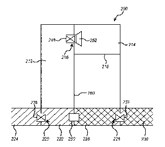
With reference to Figure 4, there is illustrated a further apparatus according
to the present disclosure.
The apparatus may be used in a method of the present disclosure that may be
described as the
"heat pump" method. The heat pump method may be performed using an apparatus
200 comprising
a source chamber 212 and a sink chamber 214. The source chamber 212 and the
sink chamber
214 are connected by a vapour flow opening 216. The vapour flow opening 216 is
located above
the maximum level, Li, reached by liquid within the apparatus (shown by line
218), such that liquid
may not pass through the vapour flow opening 216.
The source chamber 212 incorporates an opening 220, through which a first
liquid 222, also
described as the source liquid, may pass to or from a first liquid source 224.
The sink chamber 214 incorporates an opening 226, through which a second
liquid 228, also
described as the sink liquid, may pass to or from a second liquid source 230.
First liquid 222 is separated from sink liquid 228, for example, by wall 260.
The apparatus 200 incorporates a heat pump 250 that is used to transfer heat
from the sink chamber
214 to the source chamber 212.
The apparatus 200 further incorporates a mechanism for generating power 252,
such as a turbine,
interposed between the source chamber 212 and the sink chamber 214.
Power is generated as follows:
1) The source liquid 222 is introduced into the source chamber 212 from the
first liquid source
224 through the source chamber opening 220, and the sink liquid 228 is
introduced into the
sink chamber 214 from the second liquid source 230 through the sink chamber
opening 226.
2) Liquid is transferred via the vapour phase from the source liquid 222 in
the source chamber
212 to the sink liquid 228 in the sink chamber 214 due to the difference
between the vapour
pressures of the source liquid 222 and the sink liquid 228.
3) Power is generated as a result of the flow of vapour through the turbine
252.
CA 03009122 2018-06-19
WO 2017/109159
PCT/EP2016/082524
19
In addition to steps 1-3, the heat pump 250 is used to transfer heat energy
from the sink liquid 228
to the source liquid 222. Evaporation from the source liquid 222 and
condensation of the vapour in
the sink chamber 214 causes a transfer of heat from the source liquid 222 to
the sink liquid 228. This
transfer of heat causes the difference between the vapour pressures of the
source liquid 222 and
the sink liquid 228 to reduce. Reduction in the vapour pressure gradient
between the source chamber
212 and the sink chamber 214 has the effect of reducing the rate of vapour
transfer, and will
eventually halt vapour transfer completely. Use of the heat pump 250 counters
this effect.
Additionally, heat may be transferred from the sink liquid body to the source
liquid body using a heat
exchanger.
The heat pump 250 may be used to equalise the temperatures of the source
liquid 222 and the sink
liquid 228.
The difference between the vapour pressures of the source liquid 222 and the
sink liquid 228 may
be caused or increased by increasing the temperature of the source liquid 222,
by lowering the
temperature of the sink liquid 228, or, preferably, by a combination of the
two. This may be achieved
through the use of the heat pump 250, which transfers heat from the sink
liquid 228 to the source
liquid 222, such that Ti > T2, where Ti is the temperature of the source
liquid 222 and T2 is the
temperature of the sink liquid 228. Alternatively or additionally, the source
liquid body may be heated
by other means, for example using solar energy, electrical energy, or
combustion.
The source chamber opening 220 may optionally incorporate a valve 236 which
allows the source
chamber opening 220 to be closed. Optionally, if present, the source chamber
inlet valve 236 is
closed after step 1 of the above listed sequence.
The sink chamber opening 226 may optionally incorporate a valve 232 which
allows the sink
chamber opening to be closed. Optionally, if present, the sink chamber opening
valve 232 is closed
after step 1 of the above listed sequence.
When the source chamber inlet valve 236 is not closed during step 2, it is
preferable that the source
chamber opening 220 is located entirely below the surface level of the first
liquid source 224, such
that gas may not pass into the apparatus 200 during operation.
Where the atmosphere is evacuated from within the apparatus 200 and the source
chamber inlet
valve 236 is not closed during operation, it is important that gas does not
pass into the apparatus
200 through the source chamber opening 220 during operation. Likewise, where
the atmosphere is
evacuated from within the apparatus 200 and the sink chamber opening valve 232
is not closed
CA 03009122 2018-06-19
WO 2017/109159
PCT/EP2016/082524
during operation, it is important that gas does not pass into the apparatus
200 through the sink
chamber opening valve 232 during operation.
When the sink chamber opening valve 232 is closed after step 1, the sink
chamber 214 preferably
5 has a large enough volume such that the transfer of vapour from the
source liquid 222 to the sink
liquid 228 does not reduce the difference between the vapour pressures of the
source liquid 222 and
the sink liquid 228 to a level where the rate of vapour transfer is
substantially reduced. For example,
in aspects wherein the sink liquid 228 is a saline solution and the source
liquid 222 is a liquid or a
solution having a lower salinity than that of the sink liquid 228, such as
fresh water, the transfer of
10 vapour from the source liquid 222 to the sink liquid 228 will
progressively reduce the salinity of the
sink liquid 228. Such a reduction in the salinity of the sink liquid 228 will
reduce the difference
between the vapour pressures between the source liquid 222 and the sink liquid
228 to a level where
the rate of vapour transfer is reduced, or even halted.
15 When both the sink chamber opening valve 232 and the source chamber
inlet valve 236 are closed
after step 1, the sink chamber 214 preferably has a substantially greater
volume than that of the
source chamber 212.
Optionally, the vapour flow opening 216 may incorporate a valve 248 such that
it may be closed.
With reference to Figures 5 and 6, there is illustrated a fourth apparatus
according to the present
disclosure. The apparatus may be used in a method of the present disclosure
that may be described
as the "second rotational method". The second rotational method may be
performed using an
apparatus 300 comprising a chamber 302 that is configured such that it may
rotate about an axis of
rotation 304.
The chamber 302 comprises a first arm 306 extending outwards from the axis of
rotation 304.
The end of the first arm 306 furthest from the axis of rotation 304 is
referred to as the distal end 308.
The first arm 306 incorporates a sink liquid portion 344 located towards the
distal end 308 of the first
arm 306.
The sink liquid portion 344 incorporates an outlet 310.
The sink liquid portion outlet 310 is located and directed such that the
release of liquid through the
sink liquid portion outlet 310 provides a force that causes the rotational
motion of the chamber 302
about the axis of rotation 304.
CA 03009122 2018-06-19
WO 2017/109159
PCT/EP2016/082524
21
The chamber 302 further comprises a second arm 346 extending outwards from the
axis of rotation
304. The end of the second arm 346 furthest from the axis of rotation 304 is
referred to as the distal
end 348.
The second arm 346 incorporates a source liquid portion 312 located towards
the distal end 348 of
the second arm 346.
The source liquid portion 312 incorporates an inlet 314, hereafter referred to
as the source liquid
portion inlet 314, through which a first liquid 316, also referred to as the
source liquid, may pass to
or from a first liquid source 318.
The sink liquid portion 344 incorporates an inlet 320, hereafter referred to
as the sink liquid portion
inlet 320, through which a second liquid 322, also referred to as the sink
liquid, may pass to or from
a second liquid source 324.
Power is generated as follows:
1) The source liquid 316 is introduced into the source liquid portion 312
through the source
liquid portion inlet 314 from the first liquid source 318. The source liquid
316 is confined within
the source liquid portion 312 and a surface 326 of the source liquid 326 is
exposed to the
interior of the chamber 302, such that the source liquid 316 may evaporate
into the interior
atmosphere of the chamber 302.
2) The chamber 302 is rotated about the axis of rotation 304.
3) The sink liquid 322 is provided to the sink liquid portion 344 through
the sink liquid portion
inlet 320 from the second liquid source 324.
4) The sink liquid 322 exits the chamber 302 under a positive pressure
caused by the rotation
of the chamber 302 through the sink liquid portion outlet 310, providing a
reactive force that
perpetuates the rotation of the chamber 302 about the axis of rotation 304.
5) Liquid is transferred via the vapour phase from the source liquid 316 in
the source liquid
portion 312 to the sink liquid 322 in the sink liquid portion 344 due to the
difference between
the vapour pressures of the source liquid 316 and the sink liquid 322.
6) The transfer of liquid via the vapour phase in step 5 replaces the sink
liquid 322 lost through
the sink liquid portion outlet 310.
7) Power is generated as a result of the rotation of the chamber 302 about
the axis of rotation
304.
CA 03009122 2018-06-19
WO 2017/109159
PCT/EP2016/082524
22
Steps 1 to 3 may be performed in any order. Steps 4 to 7 occur simultaneously
and continuously
once steps 1-3 have been completed. The rotation of the chamber 302 is thereby
driven by the
transfer of vapour from the source liquid 316 to the sink liquid 322 via the
vapour phase.
The following features apply to the second and fourth apparatus of the present
disclosure.
Preferably, the chamber 102/302 may be coupled to an electrical alternator or
generator 140/340
such that the rotational motion of the chamber may be used to generate
electrical energy.
The sink liquid portion inlet 120/320 may incorporate a valve 128/328, such
that the flow of liquid
through the sink liquid portion inlet 120/320 may be controlled or stopped.
The sink liquid portion inlet 120/320 may incorporate a turbine 138/338. Flow
of liquid through the
turbine may be used to generate power. Alternative mechanisms for generating
power are also
contemplated, for example those employing pistons, screws or paddles.
The sink liquid portion inlet 120/320 may incorporate a pump (not shown), such
that liquid may be
actively pumped into the sink liquid portion 144/344 from the second liquid
source 124/324.
The source liquid portion inlet 114/314 may incorporate a valve 130/330, such
that the flow of liquid
through the source liquid portion inlet 114/314 may be controlled or stopped.
The source liquid portion inlet 114/314 may incorporate a turbine 136/336.
Flow of liquid through
the turbine 136/336 may be used to generate power. Alternative mechanisms for
generating power
are also contemplated, for example those employing pistons, screws or paddles.
The source liquid portion inlet 114/314 may incorporate a pump (not shown),
such that liquid may
be actively pumped into the source liquid portion 112/312 from the first
liquid source 118/318.
Preferably, the volume of sink liquid 122/322 lost from the apparatus 100/300
through the sink liquid
portion outlet 110/310 is further replaced by a quantity of sink liquid
122/322, provided from the
second liquid source 124/324 via the sink liquid portion inlet 120/320. The
addition of further sink
liquid 122/322 during steps 4 to 7 reduces and stabilises the amount by which
the sink liquid 122/322
is diluted as a result of the transfer of liquid via the vapour phase from the
source liquid 116/316 to
the sink liquid 122/322. Otherwise, dilution of the sink liquid 122/322 by the
source liquid 116/316
reduces the difference between the vapour pressures of the source liquid
116/316 and the sink liquid
122/322, which would slow the rate of vapour transfer. For example, where the
sink liquid 122/322
CA 03009122 2018-06-19
WO 2017/109159
PCT/EP2016/082524
23
is a saline solution and the source liquid 116/316 is a liquid or a solution
having a lower salinity than
that of the sink liquid, such as fresh water, the transfer of vapour from the
source liquid to the sink
liquid 122/322 progressively reduces the salinity of the sink liquid 122/322.
The sink liquid portion outlet 110/310 may optionally incorporate a valve
132/332 that may be closed
or that may regulate the flow of liquid through the sink liquid portion outlet
110/310.
The sink liquid portion outlet valve 132/332 may be closed during steps 1-3
and opened only after
step 3 is complete. This has an advantage that the sink liquid 122/322 is not
lost from the apparatus
100/300 through the sink liquid portion outlet 110/310 as it is introduced
into the apparatus 100/300
in step 3. The sink liquid portion outlet 110/310 may incorporate a nozzle
(not shown), such that the
flow of liquid through the sink liquid portion outlet 110/310 may be directed
as required.
As the chamber 102/302 rotates about the axis of rotation 104/304, its motion
will be impeded by air
resistance. It is therefore advantageous for the chamber 102/302 to be shaped
aerodynamically so
as to minimise air resistance and thereby improve the efficiency of power
generation.
The apparatus may incorporate a turbine 134/334 interposed between the source
liquid portion
112/312 and the sink liquid portion 144/344. Flow of vapour through the
turbine 134/334 may be
used to generate power.
Differences between the vapour pressures of the source liquid 1 16/31 6 and
the sink liquid 122/322
may be caused or increased by increasing the temperature of the source liquid
116/316, by lowering
the temperature of the sink liquid 122/322, or, preferably, by a combination
of the two. This may be
achieved through the use of a heat pump 142/342, which transfers heat from the
sink liquid 122/322
to the source liquid 116/316, such that T1 > Tz, where T1 is the temperature
of the source liquid
116/316 and T2 is the temperature of the sink liquid 122/322. The use of a
heat pump is
advantageous in this situation as the difference between Ti and T2 is not
large and the transfer of
heat will therefore be efficient. Alternatively or additionally, the source
liquid body may be heated by
other means, for example using solar energy, electrical energy, or combustion.
Mathematical Models
Some mathematical considerations relating to the fifth aspect of the present
disclosure are
presented below.
CA 03009122 2018-06-19
WO 2017/109159
PCT/EP2016/082524
24
In a rotating apparatus, such as that illustrated in Figures 2 and 3, the
general differential equation
for centrifugal force is
pr co2 dr = dP, (1)
where p is the density, r is the radius from the axis of rotation, co is the
angular frequency and P is
the pressure.
For the sink liquid p is constant, whereas for the vapour phase p varies. For
the vapour phase, p is
given by
p = nA v , (2)
where n is the number of moles of gas, p is the molar mass of the molecules in
the vapour phase,
and V is the volume. Substituting Equation 2 into Equation 1 gives
¨nil rcu2dr = dP. (3)
v
For an ideal gas, V is given by the ideal gas equation:
PV = nRT, (4)
where n is the number of moles of gas, R is the ideal gas constant, and T is
the temperature in K.
Substituting Equation 4 into Equation 3 gives
-7111P r co2 dr = dP. (5)
nRT
Integrating both sides of Equation 5 gives
c,o2 LA r dr = f'
(6)
RT u r-o P
PA = Poexpr ( V1
2 A2. (7)
L RT k, 2 LI
where, referring to Figure 2, PA is the vapour pressure at radius A (the
surface of the sink liquid
122), and Po is the vapour pressure at the axis of rotation 104.
CA 03009122 2018-06-19
WO 2017/109159
PCT/EP2016/082524
For the rotating sink liquid Equation 1 may be integrated directly as p is
constant for a liquid. This
gives
PB
5 pco2 fA r dr = fpA dP, (8)
2 (B2 A2)
PL" ¨2) PB PA (9)
where, referring to Figure 2, PA is the vapour pressure at radius A (the
surface of the sink liquid
10 122), Pg is the sink liquid pressure at radius B (the radius at which
the sink liquid portion outlet 110
is located) and p is the density of the sink liquid 122.
By substituting Equation 7 into Equation 9 and rearranging, the pressure (PB)
of the sink liquid 122
released from the sink liquid portion outlet 110 may be calculated according
to Equation 10:
PB = Poexprt:T2 (A22)1+ PCO2 (B22 ¨ A2\ (1 0 )
Example 1 ¨ the first rotational method
An apparatus comprising a chamber comprising a sink liquid portion is
configured such that the
sink liquid portion may rotate in the horizontal plane about an axis of
rotation. The chamber
comprises an arm, which extends 5 m from the axis of rotation in the
horizontal plane. The sink
liquid portion is located at the end of the arm that is furthest from the axis
of rotation. The arm is
square in cross section, when viewed along its longitudinal axis, with a
corresponding cross-
sectional area of 4 m2. The sink liquid portion comprises an outlet, in the
form of a nozzle. The sink
liquid portion outlet is situated at the extreme distal end of the arm and is
oriented such that liquid
exits the sink liquid portion of the chamber through the sink liquid portion
outlet in the horizontal
plane. The sink liquid portion outlet also incorporates a valve that may be
closed or that may
regulate the flow of liquid through the sink liquid portion outlet. The sink
liquid portion is connected
to a saline water source with an approximate salinity of 35 g/I by an inlet.
The sink liquid portion
inlet incorporates a valve that may be closed or that may regulate the flow of
liquid through the sink
liquid portion inlet. The sink liquid portion inlet also incorporates a pump
so that liquid may be
pumped into the sink liquid portion. The chamber further comprises a source
liquid portion. The
source liquid portion comprises a cylindrical source reservoir of diameter 2
m. The source reservoir
is connected to a fresh water source through an inlet.
CA 03009122 2018-06-19
WO 2017/109159
PCT/EP2016/082524
26
With the exception of the sink liquid portion outlet, the sink liquid portion
inlet, and the source liquid
portion, or source reservoir, inlet, the apparatus is airtight.
The apparatus comprises a spindle that is aligned along the axis of rotation
and is connected
securely at its bottommost portion to the top surface of the chamber. The
spindle passes into a
generator, which is used to convert the rotational motion of the sink chamber
into electricity.
The apparatus is operated as follows:
1) Fresh water is allowed to enter the source liquid portion, or source
reservoir, through the
source liquid portion inlet.
2) The sink liquid portion outlet valve is closed.
3) The arm comprising the sink liquid portion at its distal end is rotated to
60 RPM by running
the generator in reverse and is kept rotating at this frequency.
4) 10 m3 of saline water is pumped into the sink liquid portion through the
sink liquid portion
inlet and is confined to the distal end of the arm by the rotational motion of
the arm.
5) The sink liquid portion outlet valve is opened to allow a flow of 10 m3/min
to flow through it.
6) As liquid passes through the sink liquid portion outlet, the quantity of
liquid confined to the
distal end of the arm is kept constant at 10 m3 through the transfer of fresh
water from the
source reservoir via the vapour phase and by the transfer of saline water
through the sink
liquid portion inlet.
7) An equilibrium is reached wherein the salinity of the liquid confined to
the distal end of the
arm is constant at 20 g/I.
The rotational motion of the sink liquid portion is maintained by the flow of
liquid through the sink
liquid portion outlet and the generator is used to generate electricity from
the rotational motion of
the sink liquid portion.