Note: Descriptions are shown in the official language in which they were submitted.
CA 03009490 2018-06-21
= METALLIC CROWN CAP WITH SHORT CLOSURE SKIRT
TECHNICAL FIELD OF THE INVENTION
The present invention relates to metallic caps, particularly to a crown cap
having
an axial height less than the axial height of a crown cap from the state of
the art.
BACKGROUND OF THE INVENTION
With reference to Figure 1, there is illustrated a longitudinal section of a
crown cap
1 from the state of the art, which is formed by an inner face/outer face
laminar piece, which
includes a circular wall 2, a curved wall 3 perimetrical to the circular wall
2, and a closure
skirt 4 descending from the curved wall 3 and formed by a plurality of
projections 5 and
interleaved depressions 6. Each projection 5 is identical to all other
projections 5 of the
closure skirt 4, and each depression 6 is identical to all other depressions 6
of the closure
skirt 4. Alternatively, the crown cap 1 includes a sealing gasket 7 of
circular shape with a
perimetrical lip 8 and placed on the inner face of the circular wall 2.
In accordance with the German standard DIN 6099 of July 1997, a crown cap 1 of
twenty-one projections 5 has an internal diameter D1 of approximately 26.6 mm
(in) to
approximately 26.9 mm (in) as measured from the inner face of a rim to an
opposite rim
of the curved wall 3; an outer diameter 02 of approximately 31.9 mm (1.2559
in) to
approximately 32.3 mm (1.2716 in), measured from one rim to an opposite rim of
the
closure skirt 4; a radius of curvature R1 of the curved wall 3 of 1.5 mm
(0.05905 in) to
approximately 1.9 mm (0.07480 in) and the curved wall 3 describes an arc of
approximately 86.5 to approximately 90 ; a radius of curvature R2 of the
circular wall 2
of approximately 140 mm (5.5118 in) to approximately 190 mm (7.4803 in) and an
axial
height H1 of approximately 5.85 mm (0.2303 in) to approximately 6.15 mm
(0.2421 in).
The metallic crown caps can be of the following type:
A PRY-OFF crown cap, one that requires the use of a lever-type opener to open
the same.
A TWIST-OFF crown cap, one that requires a slight manual torque to cause the
rotation of it to open the same.
In turn, the twist-off crown caps could be classified into:
CA 03009490 2018-06-21
I
2
"Rough touch" crown cap, one whose closure skirt, once folded, has a surface
,
formed by generally pointy or sharp projections that are somewhat
uncomfortable to the
touch.
"Comfortable touch" crown cap, one whose closure skirt, once folded, has a
surface formed by generally rounded flat projections that are comfortable to
the touch.
Some examples of the twist-off, "rough touch" crown caps from the state of the
art
are described in patent documents US-5458253 and US-2005029218;
while patent documents CA-1252431, US-3648874, US-4337871, and
MX-317716 disclose some examples of twist-off, "comfortable touch" crown caps
from the state of the art.
The crown cap 1 is preferably applied on a glass bottle mouth having a crown
finish
or a threaded crown finish, in accordance with the designs established by the
Glass
Packaging Institute (GPI). Figure 2A illustrates a crown finish for a mouth 10
of a glass bottle
from the state of the art for the 600-26 series, according to the GPI. The
mouth 10 has a
sealing ring 11, a neck 12 that descends from the sealing ring 11, and a
reinforcing ring 13
that descends from the neck 12. The sealing ring 11 and the neck 12 define the
closure area
15. The sealing ring 11 has an axial height of approximately 3.7084 mm (0.146
in) to
approximately 3.8862 mm (0.153 in) and the neck 12 has a radius of
approximately
2.3876 mm (0.094 in). The sealing ring 11 has an internal rim 111 followed by
a sealing
surface 112 that is in turn followed by a curvature 113 whose outer rim 114
joins the neck
12. The internal rim 111 has a radius that does not exceed approximately
1.1938 mm
(0.47 in), the curvature 113 has a radius of approximately 3.9624 mm (0.156
in), and the
outer rim 114 has a radius of approximately 0.508 mm (0.020 in).
Figure 2B illustrates a threaded crown finish for a mouth 10 of a glass bottle
from
the state of the art for series 513, according to the GPI. The mouth 10 has a
sealing ring
11, a neck 12 that descends from the sealing ring 11, and a reinforcing ring
13 that
descends from the neck 12. The sealing ring 11 and the neck 12 define the
closure area
15. The sealing ring 11 has a minimum axial height of approximately 6.35 mm
(0.25 in),
and the neck 12 has a radius of approximately 2.3876 mm (0.094 in). The
sealing ring 11
has an internal rim 111 followed by a sealing surface 112 that is in turn
followed by a
curvature 113 followed by threads 116 and finished in an outer rim 114 joined
to the neck
12. The internal rim 111 has a radius that does not exceed approximately
0.7874 mm
(0.031 in), the curvature 113 has a radius of approximately 0.7874 mm (0.31
in) to
approximately 1.6 mm (0.063 in), and the outer rim 114 has a radius of
approximately
CA 03009490 2018-06-21
3
0.508 mm (0.020 in), while threads 116 are approximately 2.3622 [him] (0.093
in) apart
and have a radius of approximately 0.4064 mm (0.016 in) and protrude at a
distance of
approximately 0.381 mm (0.015 in) to approximately 0.5842 mm (0.023 in).
Turning now to Figure 3A, a crown cap 1 placed and folded on the mouth 10 of a
crown finish glass bottle according to the state of the art is observed, such
that the sealing
ring Ills the part of the mouth 10 interacting with the crown cap 1 in order
to seal the glass
bottle and its contents, so that on the internal rim 111 and the sealing
surface 112, the
perimetrical lip 8 of the sealing gasket 7 is compressed; while the closure
skirt 4, once folded,
is engaged to the closure area 15, particularly fixed on the outer rim 114 and
a part folded 9
toward the inside of the neck 12. The folded part 9, for the most part,
represents excess
material wasted, since the effect of gripping the crown cap 1 on the mouth 10
is effected on
the outer rim 114 and not on the neck 12, so that material is not necessary
and therefore the
amount of material used to make a crown cap 1 can be reduced.
Turning now to Figure 3B, a crown cap 1 placed and folded on the mouth 10 of a
threaded crown finish glass bottle according to the state of the art is
observed, such that
the sealing ring 11 is the part of the mouth 10 interacting with the crown cap
1 in order to
seal the glass bottle and its contents, so that on the internal rim 111 and
the sealing
surface 112, the perimetrical lip 8 of the sealing gasket 7 is compressed;
while the closure
skirt 4, once folded, is engaged to the closure area 15, particularly fixed on
the outer rim
114 and a part folded 9 toward the inside of the neck 12. The folded closure
skirt 4 has a
thread 115 interlocked onto the threads 116 of the mouth 10 of the threaded
crown finish
glass bottle. The folded part 9, for the most part, represents excess material
wasted, since
the effect of gripping the crown cap 1 on the mouth 10 is effected on the
outer rim 114
and not on the neck 12, so that material is not necessary and therefore the
amount of
material used to make a crown cap 1 can be reduced.
Currently, efforts have been made to reduce the amount of material used to
make a
crown cap. Two examples of embodiments for this purpose, using the same
inventive
principle, are described in US patent documents US-3273736 and US-8056743B2.
Patent US-3273736 discloses a pry-off crown cap, whose curved wall has a
radius
much wider than the radius of a conventional crown cap (as described in the
German
standard DIN 6099), whose size is approximately 2 mm (0.08 in) to
approximately 2.5 mm
(0.10 in) and with a seal of no more than 160 mg of weight. Therefore, die
cutting this
crown cap requires a circular sheet cutout with a diameter from approximately
36.6 mm
(1.44 in) to approximately 37.3 mm (1.47 in).
CA 03009490 2018-06-21
4
US-8056743B2 discloses a pry-off crown cap 1, as illustrated in Figure 3C,
whose
curved wall 3 has a radius similar to the radius of the curvature 113 of the
sealing ring 11 of
a crown finish for a glass bottle mouth, series 600-26 according to the GPI.
That is, the curved
wall 3 has a radius of approximately 4 mm (0.157 in), which allows the crown
cap 1 to be
coupled directly onto the radius curvature 113 of approximately 3.9624 mm
(0.156 in) from a
mouth 10 of a crown finish glass bottle. This direct coupling of the curved
wall 3 of the crown
cap 1 on the curvature 113 of the sealing ring 11 of the glass bottle mouth
allows making a
crown cap 1 that requires less metal. Therefore, to die cut this crown cap, a
circular sheet
cutout with an approximate diameter of 35.5 mm (1.4 in) is required.
The crown cap of US Pat. No. 3273736 and the crown cap of patent US-8056743B2
have the disadvantage that they can only be used to cover a crown finish glass
bottle mouth
(e.g., GPI 600-26 series), as they cannot be used in a threaded crown finish
glass bottle
mouth, because the radius of curvature of its respective curved wall is at
least 150% greater
than the curvature of the sealing ring of a threaded crown finish glass bottle
mouth, and
therefore it would have coupling and clamping problems, thereby causing a non-
airtight seal.
Another disadvantage of these crown caps disclosed in the patents US-3273736
and US-
8056743B2 is that once the closure skirt is folded on a crown finish glass
bottle mouth, there
is an part folded in excess toward the inside of the neck of the glass bottle
mouth.
In view of the foregoing, it is necessary to provide a crown cap having an
axial
height less than the axial height of a crown cap from the state of the art,
which at the
same time retains the sealing characteristics and allows to be crowned on a
glass bottle
mouth with crown finish or threaded crown finish, and which is also a pry-off
or twist-off
crown cap, and comfortable touch.
SUMMARY OF THE INVENTION
In view of what has been disclosed above and with the purpose of solving the
limitations found in crown caps, it is the purpose of the invention to offer a
crown cap in its
state prior to its closure to seal a mouth of a crown finish or threaded crown
finish glass bottle,
the crown cap comprising a inner face/outer face laminar piece, formed by a
circular wall, a
curved wall perimetrical to the circular wall, and a closure skirt that
descends radially
downward and outward from the curved wall and formed by a plurality of
interleaved
projections and depressions; such that the curved wall has a radius of
curvature of 1.5 mm
(0.590551 in) to 1.9 mm (0.748031 in) and an arc less than 86 , resulting in a
shorter closure
skirt than the closure skirt of a crown cap from the state of the art.
CA 03009490 2018-06-21
It is also a purpose of the present invention to provide a closed crown cap by
sealing a mouth of a crown finish or threaded crown finish bottle, the closed
crown cap
comprising a laminar piece formed by a circular wall, a curved wall
perimetrical to the
circular wall, and a closure skirt marginally folded on the mouth of the glass
bottle and
descending radially downward from the curved wall, such that the closure skirt
is formed
with minor projections and interleaved gripping depressions, wherein each
minor
projection includes a central depression between a pair of opposite second
convex flanks
and each gripping depression includes a securing groove and a contact wall.
Another purpose of the present invention is to provide a method for making a
crown
cap with a short closure skirt for sealing a crown finish or threaded crown
finish glass bottle,
the method having the steps of providing a circular sheet cutout of a diameter
from
33.4949 mm (1.3187 in) to 35.5346 mm (1.399 in); and pushing the circular
sheet cutout
with a forming punch against a forming die to form a circular wall, a curved
wall with a
radius of curvature from 1.5 mm (0.590551 in) to 1.9 mm (0.748031 in) and an
arc less
than 86 , and a closure skirt with projections and depressions.
Finally, it is a purpose of the present invention to provide a method for
sealing with
a crown cap a crown finish or threaded crown finish glass bottle, the method
having the
steps of providing a glass bottle having a crown finish or threaded crown
finish mouth;
placing a crown cap on the mouth of the glass bottle, the crown cap having a
circular wall,
a curved wall perimetrical to the circular wall, and a closure skirt
descending radially
downward and outward from the curved wall and formed by a plurality of
interleaved
protrusions and depressions, and wherein the curved wall has a radius of
curvature from
1.5 mm (0.590551 in) to 1.9 mm (0.748031 in) and an arc less than 86 ; and
vertically and
concentrically running a crowning die on the crown cap to collapse and fold
the closure skirt
marginally on the mouth of the glass bottle, wherein each protrusion collapses
vertically
and forms a smaller projection that includes a central depression between a
pair of opposed
second convex flanks, and each depression collapses to form a gripping
depression
including a securing groove and a contact wall.
BRIEF DESCRIPTION OF THE FIGURES
The characteristic features of the invention are described in the following
paragraphs in conjunction with the figures that accompany it, which have the
purpose
of defining the invention but without limiting the scope thereof.
CA 03009490 2018-06-21
6
Figure 1 shows a longitudinal sectional view of a crown cap from the state of
the
art, in accordance with the German standard DIN 6099 of July 1997.
Figure 2A shows a cross-sectional view of a crown finish for a mouth of a
glass bottle
from the state of the art, according to the Glass Packaging Institute for
series 600-26.
Figure 2B shows a cross-sectional view of a threaded crown finish for a mouth
of
a glass bottle from the state of the art, according to the Glass Packaging
Institute for
series 513.
Figure 3A shows a cross-sectional view of the crown cap of Figure 1 sealing
the mouth
of the crown 'finish glass bottle of Figure 2A
Figure 3B shows a cross-sectional view of a crown cap of Figure 1 sealing the
mouth
of the threaded crown finish glass bottle of Figure 2B.
Figure 3C shows a cross-sectional view of a crown cap from the state of the
art
disclosed in US patent US-8056743B2 and sealing the mouth of the glass bottle
of Figure
2A.
Figure 4A shows a perspective view of a crown cap according to the invention.
The crown cap is illustrated in its pre-closure condition to seal a mouth of a
glass bottle.
Figure 4B shows a side view of the crown cap of Figure 4A, according to the
invention.
Figure 4C shows a detailed view of section D of the crown cap of Figure 4B,
according
to the invention.
Figure 5A shows a perspective view of a forming die to form a crown cap in its
pre-
closure state, according to the invention.
Figure 5B shows a top view of the forming die shown in Figure 5A.
Figure 5C shows a cross-sectional view of the forming die shown in Figure 5A
through
the cutting line B-B'.
Figure 6 shows a comparison of axial height and curved wall of a) a profile of
a
crown cap from the state of the art, in accordance with the German standard
DIN 6099 of
July 1997, b) a profile of a crown cap in accordance with US Pat. No.
8056743B2, and c)
a crown cap according to the present invention.
Figure 7A shows a perspective view of a closed crown cap according to the
invention,
sealing a crown finish glass bottle mouth.
Figure 7B shows a detailed view of section E of the crown cap of Figure 7A,
according
to the invention.
CA 03009490 2018-06-21
7
Figure 7C shows a cross-sectional view of a crown cap according to the
invention,
sealing a threaded crown finish glass bottle mouth.
DETAILED DESCRIPTION OF THE INVENTION
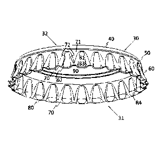
With reference to Figures 4A, 4B, and 4C, the crown cap 30 is shown in its pre-
closure condition to seal a mouth of a crown finish or threaded crown finish
glass bottle.
The crown cap 30 is an inner face 31 and outer face 32 laminar piece formed by
a
circular wall 40, a curved wall 50 perimetrical to the circular wall 40, and a
closure skirt
60 descending from the curved wall 50 and formed by a plurality of projections
70 and
interleaved depressions 80. Each projection 70 is identical to all the other
projections
70 of the closure skirt 60, and each depression 80 is identical to all the
other
depressions 80 of the closure skirt 60.
The crown cap 30 of the present invention is manufactured based on circular
sheet cutouts specially prepared for that purpose. The metallic sheets,
preferably made
of steel, can be continuous (in rolls) or in cuts or units with the
appropriate measures,
depending on the type of machine to be used. As an example, metallic sheets
can be
used with dimensions of 911.5806 mm (35.889 in) for 887.3998 mm (34.937 in)
and
with a thickness with a range of approximately 0.160 mm (0.00629 in) to
approximately
0.210 mm (0.00826 in).
For punching the crown cap 30, a circular sheet cutout with a diameter of
approximately 33.4949 mm (1.3187 in) to approximately 35.5346 mm (1.399 in) is
required. This represents a reduction in required material compared to the
circular sheet
cutout required for making crown caps, in accordance with the aforementioned
US
Patents US-3273736 and US-805674382. According to the invention, using the
aforementioned metallic sheet can [provide?] an increase in the number of
crown caps
30 that can be produced compared to the number of crown caps from the state of
the art
that can be produced using this same sheet.
After the circular sheet is cut by a cutting die, in almost the same action, a
forming
punch pushes the circular sheet cutout against a forming die (see Figure 5A).
The punch
establishes the shape and dimensions of the circular wall 40 and the curved
wall 50,
and the size of the closure skirt 60, while the forming die basically shapes
and gives
dimension to the projections 70 and depressions 80. In this way, a crown cap
30 of
basic form is obtained in its state prior to its closure, which will later be
placed on the
mouth of a glass bottle to close the same by the use of a crowning machine.
The closure
skirt 60 has from 17 to 27 projections.
8
Each projection 70 can have a width of A and each depression 80 can have a
width of B. Preferably, the width A of each projection 70 is smaller than the
width B of
each depression 80.
The curved wall 50 is merged with the circular wall 40 and the closure skirt
60,
thereby defining a radius of curvature R1 from approximately 1.5 mm (0.590551
in) to
approximately 1.9 mm (0.748031 in). The curved wall 50 has an arc of less than
86 ,
preferably from approximately 68 to approximately 76 , whereby the axial
distance
between the surface of circular wall 40 and the beginning of the closure skirt
60 is shorter
in comparison with a crown cap from the state of the art, thereby promoting a
smoother
transition between the curved wall 50 and the closure skirt 60 compared to a
crown cap
from the state of the art, and therefore, the crown cap 30 has an axial height
H2 from
approximately 5.3 mm (0.208661 in) to approximately 5.8 mm (0.228346 in).
The crown cap 30 has an inner diameter D1 from approximately 26.6 mm
(1.04724 in) to approximately 26.9 mm (1.05905 in), measured from the inner
face of a
rim to an opposite rim of the curved wall 50, and an outer diameter D2 from
approximately 31.9 mm (in) to approximately 32.3 mm (in) measured from one rim
to
an opposite rim of the closure skirt 60.
From the perspective of the outer face of the crown cap 30, its circular wall
40 is
slightly convex, having a radius of curvature R2 from approximately 178 mm
(7.0078 in)
to approximately 228 mm (8.9763 in).
The outer face 32 is covered, optionally, by a coating on which an
advertisement
is printed, for example, the brand of the beverage or the bottler. In an
alternative
embodiment, the inner face 31 could be covered with a coating.
Alternatively, the crown cap 30 includes a sealing gasket 90 of circular
shape,
positioned on the inner face 31 and particularly adhered to or formed on the
coating
covering the circular wall 40. The sealing gasket 90 allows an airtight seal
on the mouth
of the glass bottle to be sealed with the crown cap 30.
As shown in Figures 4B and 4C, and taking as a reference for orientation
purposes the perspective of the outer face 32 of the crown cap 30, each
projection 70
includes an inverted triangular wall 71 formed between a pair of opposite
convex flanks
72. The inverted triangular wall 71 descends from the curved wall 50 in the
outward
direction of the crown cap 30, thereby defining a radius of curvature R3, and
it is gently
merged with the convex flanks 72.
Date Recue/Date Received 2022-12-09
CA 03009490 2018-06-21
Preferably, R3 is from approximately 8.74 mm (0.3440 in) to approximately
9.04 mm (0.3555 in). On the other hand, each depression 80 includes a full
central wall
81 formed between a pair of opposite convex flanks 72, and a concave bottom
wall 83.
The full central wall 81 descends from the curved wall 50 substantially
parallel to the
central axis of the crown cap 30, and this gently merges with the opposite
convex flanks
72. The lower concave wall 83 descends from the full central wall 81 and from
the
convex flanks 72 in the outward direction of the crown cap 30.
Figures 5A and 5B depict an exemplary shaped die that can be used to form a
crown cap in its pre-closure state, according to the present invention. As
shown, a forming
die 200 includes a cylindrical wall 201, a forming portion 202 that is an
enlargement of
the cylindrical wall 201, and a holding portion 203 that is an enlargement of
the cylindrical
wall 201. The cylindrical wall 201 and the forming portion 202 can define a
cylinder having
an opening 204 with enlargement therethrough. As shown in Figures 5A and 5B,
the
forming portion 202 includes alternating grooves 205 and ledges 206.
Preferably, the
grooves 205 are circumferentially and regularly spaced apart by alternating
ledges 206,
such that each groove 205 is identical to all of the other grooves 205 of the
forming portion
202, and each ledge 206 is identical to all of the other ledges 206 of the
forming portion
202. Meanwhile, the forming die 200 shows twenty-seven grooves 205 and ledges
206;
it is to be understood that the forming die 200 may include any number of
grooves 205
and ledges 206. For example, the forming die 200 may include from twenty-one
to twenty-
seven grooves 205 and ledges 206.
As shown in Figure 5B, each groove 205 may have a maximum width of C, and
each ledge 206 may have a maximum width of D, such that C is greater than D.
Since
C is greater than D, a crown cap may be made having wider depressions than the
width
of the projections.
Figure 5C is a cross-sectional view through line BB of Figure 5B and shows a
representative sample of a groove 205 and ledge 206. As shown in Figures 5B
and 5C,
each ledge 206 can include a substantially flat portion 208 and a curved
portion 209
that is an enlargement of the flat portion 208. The curved portion 209 may
extend toward
the center of the forming die 200 at a radius of curvature R5 below the
horizontal plane.
As shown, each ledge 206 may also include a distal end 210. Preferably, each
distal
end 210 is curved and has a radius R6. The surface of the flat portion 208 at
the edge
of the distal end 210 has a height H.
CA 03009490 2018-06-21
As shown, each groove 205 includes a first vertical fiat wall 211, an inclined
surface
212 that is an enlargement of the first vertical fiat wall 211, and a second
vertical fiat wall
213 which is an enlargement of the inclined surface 212. The first vertical
flat wall 211
extends at approximately a 900 angle from the flat portion 208 and
substantially parallel to
the axis of the forming die 200. The inclined surface 212 extends toward the
center of the
forming die 200 at an angle 0 below the horizontal plane.
Now, figure 6 shows a comparison of axial height and curved wall of a) a
profile of a
crown cap from the state of the art, in accordance with the German standard
DIN 6099 of
July 1997, b) a profile of a crown cap in accordance with US Pat. No.
8056743B2, and c) a
crown cap according to the present invention. In this comparison, the effect
of reducing the
arc dimension of the curved wall on the axial height of the crown cap for a
curved wall having
a similar radius of curvature is illustrated. In a first comparison, the
radius of curvature of the
curved wall 3 of the crown cap from the state of the art of a) and the radius
of curvature of
the curved wall 50 of the crown cap of the invention of c) are similar.
However, the arc of the
curved wall 50 of the crown cap of the invention of c) is smaller than the arc
of the curved
wall 3 of the crown cap from the state of the art of a), thus promoting a
significant reduction
of the axial height of the crown cap of the invention of c) with respect to
the crown cap from
the state of the art of a). In a second comparison, the crown cap from the
state of the art of
a) and the crown cap of US patent US-8056743B2 of b) has the same axial
height, but they
differ in the radius of curvature and the arc size of their respective curved
wall 3, the radius
of curvature of the curved wall 3 of the crown cap of US Pat. No. 805674382 of
b) being
much greater than the radius of curvature of the curved wall 3 of the crown
cap from the state
of the art of a), but the arc of the curved wall 3 of the crown cap of US Pat.
No. 8056743B2
of b) is smaller than the arc of the curved wall 3 of the crown cap from the
state of the art of
a). In a third comparison, the crown cap of the invention of c) and the crown
cap of US patent
US-8056743B2 of b) differ in their axial height, in the radius of curvature,
and in the arc of
their respective curved wall, the axial height H2 of the crown cap of the
invention of c) being
smaller than the axial height H1 of the crown cap of US Pat. No. 805674362 of
b), while the
radius of curvature of the curved wall 3 of the crown cap of US Pat. No.
8056743B2 of b) is
much larger than the radius of curvature of the curved wall 50 of the crown
cap of the
invention of c).
With reference to Figures 7A and 7B, a sealed crown finish glass bottle mouth
10 is
illustrated with a folded crown cap 30. The crown cap 30 is placed on the
mouth 10 of the
glass bottle by the use of a crowning machine (not shown) that vertically and
concentrically
runs a crown die (not shown) that collapses and folds the closure skirt 60
marginally over the
CA 03009490 2018-06-21
,
11
mouth 10 of the glass bottle, such that when the closure skirt 60 is folded,
each projection 70
(see Figure 4C) collapses vertically and forms a minor projection 73 that
includes a central
depression 74 between a pair of convex opposite second flanks 75; while each
depression
80 collapses to form a gripping depression 84 which includes a gripping groove
85 and a
contact wall 86. Each second convex flank 75 of the minor projection 73
originates from the
collapse of a portion of the inverted triangular wall 71 and of a convex flank
72 (see Figure
4C), while the securing groove 85 and contact wall 86 originates from the
collapse of the flat
central wall 81 and concave bottom wall 83 (see Figure 4C).
The crown cap 30, once closed, forms a circular wall 40, a curved wall 50
perimetrical to the circular wall 40, and a folded closure skirt 60 descending
from the
curved wall 50 and formed by a plurality of minor projections 73, central
depressions
74, and interleaved gripping depressions 84. Each gripping depression 84 has a
greater
width at its free rim and a smaller width at its rim that merges with the
curved wall 50,
while each minor projection 73 has a smaller width at its free rim and a
greater width at
its rim that merges with the curved wall.
The curved wall 50 is merged with the circular wall 40 and the closure skirt
60, thereby
defining a radius of curvature R1 from approximately 1.5 mm (0.590551 in) to
approximately
1.9 mm (0.748031 in).
From the perspective of the outer face of the crown cap 30, its circular wall
40 is
slightly convex, having a radius of curvature R2 from approximately 178 mm
(7.0078 in)
to approximately 228 mm (8.9763 in).
The closed crown cap 30 has an axial height H3 from approximately 5.3 mm
(0.208661 in) to approximately 5.8 mm (0.228346 in),
With reference to Figure 7C, a sealed threaded crown finish glass bottle mouth
10
is illustrated with a folded crown cap 30. In addition to the technical
elements described
above in figures 7A, 7B, and 7C, the folded closure skirt 60 further has a
threading 85
interlocked onto the threads 116 of the mouth 10 of the threaded crown finish
glass bottle.
The plurality of minor projections 73, central depressions 74, and gripping
depressions 84 increase the area of contact of the surface of the folded
closure skirt 60
for a correct and comfortable grip of the crown cap 30 for manual opening or
by applying
a torque to turn it.
Each minor projection 73 in its central depression 74 is sufficiently
separated from
the outer rim of the mouth 10 of the glass bottle to allow the engagement of a
bottle
CA 03009490 2018-06-21
,
12
opener for correct opening of the crown cap 30 under this embodiment, without
causing
,
damage to the mouth 10 of the glass bottle or to the crown cap 30 itself.
Based on the alternative embodiments described, it is contemplated that
modifications to each of the described embodiments, as well as alternative
application
embodiments, will be considered obvious to a person skilled in the art of the
technique under
the present specification. It is therefore contemplated that the claims
encompass said
modifications and alternatives that are within the scope of the present
invention.