Note: Descriptions are shown in the official language in which they were submitted.
CA 03009790 2018-06-26
WO 2017/151115
PCT/US2016/020215
METHOD FOR FLEXIBLE STRUCTURED GRIDDING USING NESTED
LOCALLY REFINED GRIDS
BACKGROUND
Reservoir simulation is an area of reservoir engineering that employs computer
models to predict the transport of fluids, such as oil, water, and gas, within
a reservoir.
Reservoir simulators are used by petroleum producers in determining how best
to develop new
fields, as well as generate production forecasts on which investment decisions
can be based in
1() connection with developed fields.
Reservoir simulation software models are typically implemented using a number
of
discretized blocks, referred to interchangeably herein as "blocks," "grid
blocks," or "cells."
Models can vary in size from a few grid blocks to hundreds of millions of grid
blocks. In these
software simulations, it is common to model a reservoir using a simulation
grid formed of
blocks and then simulate reservoir properties (e.g., pressure, temperature,
porosity,
permeability) within each block to predict flow. For example, such modeling
may be
particularly useful in low permeability reservoirs for determining how many
and where
fractures should be induced in a reservoir to achieve a certain flow over a
period of time.
BRIEF DESCRIPTION OF THE DRAWINGS
There are disclosed in the drawings and the following description methods and
systems
employing grid blocks for modeling a geologic formation. In the drawings:
FIG. 1 illustrates an example of a simulation grid;
FIG. 2 illustrates an example of a locally refined grid selected within the
simulation
grid;
FIG. 3 is an enlarged view of the locally refined grid;
FIGs. 4(a), 4(b), and 4(c) illustrate construction of a simulation grid
according to one
embodiment;
FIG. 5 illustrates an example in which a grid block around an area of interest
is refined;
FIG. 6 illustrates an example in which multiple grid blocks around an area of
interest
are refined;
FIG. 7 illustrates an example of a uniform refinement of a grid block in an
area of
interest;
FIG. 8 illustrates an example of a non-uniform refinement of a grid block;
1
CA 03009790 2018-06-26
WO 2017/151115
PCT/US2016/020215
FIGs. 9 and 10 illustrate construction of a simulation grid according to one
embodiment;
FIGs. 11 and 12 illustrate examples of uniform and/or non-uniform refinement
of
multiple grid blocks;
FIG. 13 is a flowchart showing an illustrative modeling method; and
FIG. 14 is a simplified block diagram of a computer system adapted for
implementing
a reservoir simulation system.
It should be understood, however, that the specific embodiments given in the
drawings
and detailed description do not limit the disclosure. On the contrary, they
provide the
foundation for one of ordinary skill to discern the alternative forms,
equivalents, and
modifications that are encompassed together with one or more of the given
embodiments in
the scope of the appended claims.
DETAILED DESCRIPTION
Disclosed herein are methods and systems for modeling a geologic formation
using grid
blocks. In at least some embodiments, a method includes identifying a
particular area (or two
or more areas) in a representation of the geologic formation and providing a
grid block to
encompass the particular area, without reference to one or more underlying
grid boundaries.
The method also includes providing a plurality of buffer grid blocks adjacent
to the grid block
and refining a resolution of the grid block. Providing the grid block to
encompass the particular
area without reference to the one or more underlying grid boundaries allows
the resolution of
the grid block to be refined without restriction by the one or more underlying
grid boundaries.
A related computing system includes a display and a processor coupled to the
display.
The processor is configured to: identify a particular area (or two or more
areas) in a
representation of a geologic formation displayed on the display; control the
display to display
a grid block to encompass each particular area, without reference to one or
more underlying
grid boundaries; control the display to display a plurality of buffer grid
blocks adjacent to the
grid block; and refine a resolution of the grid block. Controlling the display
to display the grid
block to encompass the particular area without reference to the one or more
underlying grid
boundaries allows the resolution of the grid block to be refined without
restriction by the one
or more underlying grid boundaries.
Reservoir simulation commonly utilizes numerical representations of a
reservoir based
off the physics, either as the reservoir currently exists or as it is
envisioned to exist at some
2
CA 03009790 2018-06-26
WO 2017/151115
PCT/US2016/020215
point in the future, e.g., before any wells are drilled, prior to any field
development and during
field development. Such a representation of the reservoir, combined with
additional data about
proposed or existing wells and development strategy, facilitates prediction of
how the reservoir
might perform in terms of reservoir stimulation and production.
The simulation may utilize a grid. FIG. 1 illustrates an example of a
simulation grid
108. The simulation grid 108 is applied to a geologic formation such as a
subterranean
reservoir. The simulation grid 108 is characterized by (or divided into) grid
blocks 110. Each
of the grid blocks 110 represents a respective portion of the reservoir.
Therefore, a particular
grid block 110 is used to discretely characterize a corresponding portion of
the reservoir. For
example, reservoir engineering data may be collected on a grid block level. A
functional model
of the reservoir may be created by simulating reservoir properties such as
flow rate, pressure,
temperature, porosity, and permeability within each grid block 110.
In the FIG. 1, the grid blocks 110 are illustrated as being substantially
uniform in shape
and size. However, it is understood that the grid blocks 110 may have
different shapes and/or
sizes. For example, any two or more of the grid blocks 110 may have different
sizes, in order
to represent portions of the reservoir having different sizes. Further, along
a particular direction
(e.g., x-direction, y-direction), the simulation grid 108 may be divided into
any of various
numbers of grid blocks 110.
For ease of description, the simulation grid 108 is described as being
composed of grid
blocks 110 that reside in one plane (e.g., an x-y plane). However, it is
understood that features
disclosed herein are equally applicable to a simulation grid composed of grid
blocks that reside
in other planes (e.g., an x-z plane) as well as a simulation grid composed of
three-dimension
grid blocks that are defined by the x-, y- and z-directions.
As noted earlier, the simulation grid 108 may be used to model a reservoir.
The
reservoir may be a shale reservoir. Typically, shale reservoirs exhibit a
permeability that is
quite low when compared to other types of geologic reservoirs. For example,
shale reservoirs
may be less permeable than other geologic reservoirs by a factor of 106. Lower
levels of
permeability result in slower fluid and pressure. Increased surface area in
contact with such a
reservoir can be accomplished by creating fractures. The areas around
fractures typically
require fine grids in order to suitably capture pressure transient behavior.
Accordingly, it is
often beneficial to model certain portions of a shale reservoir (e.g., to
model parameters such
as flow) using a finer grid scale as compared to other portions of the
reservoir or other types of
reservoirs. Such other reservoirs may be modeled acceptably using grid blocks
that are less
refined.
3
CA 03009790 2018-06-26
WO 2017/151115
PCT/US2016/020215
Further, the reservoir may include one or more geologic features or areas of
interest,
such as the fractures described earlier, wellbores or the like. Such features
may be either man-
made or naturally occurring. For example, a particular structure may be an
existing structure
of the reservoir or a proposed structure selected to achieve a particular flow
in a modeled
formation.
The simulation grid 108 may be used to simulate pressure flow at a number of
discrete
locations around the structure (e.g., an existing or a proposed fracture).
Ultimately, this model
predicts the areas of the reservoir in which fluid and/or pressure movement
associated with the
fracture will occur. To more accurately predict pressure flow in such regions,
finer grids can
be used to model the region(s) of the reservoir in which significant fluid
and/or pressure
movement are expected to occur. Such finer grids are commonly referred to as
local grid
refinements (LGRs). Because the higher resolution associated with LGRs involve
heavier
computational loads, LGRs are typically applied only to specific areas of
interest (e.g., areas
around a fracture), such that other areas of the reservoir are modeled using
coarser grids.
FIG. 2 illustrates the selection of a locally refined grid 212 embedded within
the
simulation grid 108. The locally refined grid 212 is defined with reference to
the simulation
grid 108. More specifically, the locally refined grid 212 is defined by
borders of the grid blocks
110. As illustrated in the x-direction of FIG. 2, the locally refined grid 212
is 3 grid blocks
wide (the locally refined grid 212 is embedded within 3 grid blocks of the
simulation grid 108).
More specifically, in the x-direction, a topmost border of the locally refined
grid 212 is defined
by (or coincident with) borders of the grid blocks 110-1, 110-2, and 110-3. In
the y-direction
of FIG. 2, the locally refined grid 212 is 5 grid blocks long. More
specifically, in the y-
direction, a leftmost border of the locally refined grid 212 is defined by
borders of the grid
blocks 110-1, 110-4, 110-5, 110-6, and 110-7. For purposes of reducing
computational load,
the locally refined grid 212 is sized so as to reduce unnecessary application
of fine grids in a
reservoir simulation model. Accordingly, the size of the locally refined grid
212 is based on
the size of an area of interest.
An LGR is applied to the simulation grid. The application of the LGR is
illustrated
more clearly in FIG. 3, which is an enlarged view of the locally refined grid
212 of FIG. 2.
One or more grid blocks that are within the locally refined grid 212 are sub-
divided into a
plurality of smaller (i.e., finer) grid blocks. Thus, when the reservoir model
is simulated,
pressure and/or fluid movement may be discretely calculated for each finer
grid block to
achieve a more accurate simulation.
4
CA 03009790 2018-06-26
WO 2017/151115
PCT/US2016/020215
As illustrated in FIG. 3, resolution in one or more blocks within the locally
refined grid
212 is increased. The increase in resolution may vary across different grid
blocks. For example
-- as illustrated in FIG. 3, resolution in grid blocks 110-1 and 110-3 is
uniformly increased by
a factor of 3 in the x-direction. In other words, along the x-direction, each
of grid blocks 110-
1 and 110-3 is evenly divided into 3 (smaller) blocks. For example, resolution
in grid block
110-2 is uniformly increased by a factor of 7 in the x-direction. In other
words, along the x-
direction, grid block 110-2 is evenly divided into 7 (smaller) blocks. More
generally, each grid
block in the locally refined grid 212 can be sub-divided into any of various
numbers of smaller
blocks, relative to a particular direction (e.g., x- or y-direction).
Refinement of the locally refined grid 212 is hampered or restricted by the
borders of
various grid blocks of the simulation grid 108. The locally refined grid 212
is embedded within
grid blocks of the simulation grid 108 (e.g., grid blocks 110-1, 110-2, 110-3,
etc.) Refinement
of the locally refined grid 212 is performed in a manner that is observant of
the borders of such
grid blocks.
For example, each of grid blocks 110-1, 110-2, 110-3 may represent a width of
100 feet
in the x-direction. By uniformly subdividing a particular grid block (e.g.,
grid block 110-1)
into 2, blocks are created, where each represents a width of 50 feet.
Similarly, by uniformly
subdividing the grid block 110-1 into 3, blocks are created, where each
represents a width of
33-1/3 feet are created. As such, blocks are created, where each represents a
width of 100/N
feet, where N denotes an integer greater than 0. However, in cases where 100
feet is not equal
to an integer multiple of a particular width (e.g., such as 37 or 47 feet, N
would be a non-
integer), it is not possible to create equally sized blocks, each of the
blocks representing the
particular width.
It is recognized that one or more grid blocks may be subdivided in a non-
uniform
manner. For example, the grid block 110-1 may be subdivided into blocks that
represent widths
of 37 feet, 47 feet and 16 feet, respectively. However, the refinement of the
grid block is
confined or restricted, in that the widths represented by the smaller blocks
add up to 100 feet
(the width represented by grid block 110-1).
According to various embodiments, a coarse grid block is created. The grid
block
covers a particular area (or structure) of interest, and is defined without
reference to an
underlying grid such as simulation grid 108 (or grid blocks 110 that make up a
simulation grid).
Other coarse grid blocks (buffer grid blocks) are created around the grid
block, in order to
model areas outside of the area of interest. Because the coarse grid block is
defined without
reference to an underlying simulation grid, refinement of the coarse grid
block can be
5
CA 03009790 2018-06-26
WO 2017/151115
PCT/US2016/020215
performed without being hampered or encumbered by borders associated with such
a
simulation grid.
According to various embodiments, a grid for modeling an entire area is
constructed
based on one or more particular areas of interest (e.g., fracture patterns)
that are to be modeled,
as well as the size(s) of the particular area(s). A coarse grid block(s)
(corresponding to the
area(s) of interest) may be refined independent of buffer grid blocks that are
provided around
the coarse grid block(s).
First, a grid that is constructed based on a single area of interest will be
described with
reference to FIGs. 4(a), 4(b), and 4(c). FIGs. 4(a), 4(b), and 4(c) illustrate
construction of a
grid according to one embodiment.
In a representation of a geologic formation (e.g., a reservoir such as a shale
reservoir),
a specific structure 402 is identified. For example, the structure 402 may be
a fracture pattern.
With reference to FIG. 4(a), a grid block 404 is created to encompass the
structure 402. Similar
to the locally refined grid 212 of FIGs. 2 and 3, the grid block 404 is for
modelling a specific
area of interest in a reservoir. However, unlike the locally refined grid 212,
the grid block 404
is defined without reference to an underlying grid and/or underlying grid
blocks (e.g.,
simulation grid 108 and/or grid blocks 110 of FIG. 1). As such, the dimensions
of the grid
block 404 can be selected irrespective of grid lines (or borders) that are
associated with such
constructs. Further, as will be described in more detail later, the grid block
404 can be refined
(e.g., subdivided) without being hampered or restricted by such underlying
grid lines.
With reference to FIG. 4(b), a grid 406 is created. The grid 406 encompasses
an entire
area (e.g., an entire area of the reservoir) to be modelled. Accordingly, the
grid 406 not only
covers the grid block 404 but also a buffer area 408 adjacent to the grid
block 404.
For purposes of LGR, the buffer area 408 may be subdivided into separate
buffer grid
blocks. As illustrated in FIG. 4(c), the buffer area 408 is subdivided into
buffer grid blocks
408a, 408b, 408c, 408d, 408e, 408f, 408g, and 408h.
The buffer grid blocks 408a, 408b, 408c, 408d, 408e, 408f, 408g, and 408h may
be
refined. FIG. 5 illustrates an example in which the buffer grid block 408a is
refined. FIG. 6
illustrates an example in which multiple buffer grid blocks 408a, 408b, 408c,
408d, 408e, 408f,
408g, and 408h are refined. In FIGs. 5 and 6, buffer grid blocks are
illustrated as being
subdivided in a uniform manner. However, it is understood that the buffer grid
blocks may be
subdivided in a non-uniform manner. Also, each of the buffer grid blocks may
be refined in a
manner (uniform or non-uniform) that is independent of the manner in which
other buffer grid
blocks are refined.
6
CA 03009790 2018-06-26
WO 2017/151115
PCT/US2016/020215
Grid block 404 is also refined. According to various embodiments, the grid
block 404
is refined to provide a higher (finer) level of resolution relative to the
buffer grid blocks 408a,
408b, 408c, 408d, 408e, 408f, 408g, and 408h. As such, parameters such as
pressure, flow rate
may be predicted more precisely in the geologic region represented by the grid
block 404. As
noted earlier, the refinement of the grid block 404 is performed without
reference to an
underlying simulation grid such as simulation grid 108 (or grid blocks 110
that make up a
simulation grid). Accordingly, refinement of the grid block 404 can be
performed without
being hampered or restricted by borders associated with such a simulation grid
(or its
constituent grid blocks).
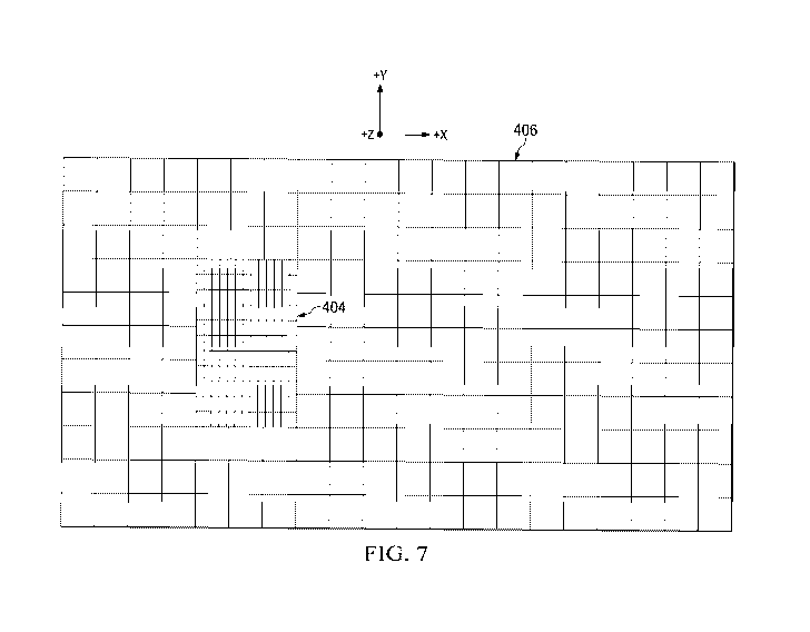
FIG. 7 illustrates an example of a uniform refinement of a grid block in an
area of
interest. With reference to FIG. 7, resolution in the grid block 404 is
uniformly increased in
the x- and y- directions. In other words, along the x- and y- directions, the
grid block 404 is
evenly divided into smaller blocks. FIG. 8 illustrates an example of a non-
uniform refinement
of a grid block. In more detail, FIG. 8 illustrates a non-uniform refinement
of the grid block
404, where the grid block is sub-divided into blocks of different sizes. It is
understood that
refinement of the grid block 404 may be performed in another manner. For
example, the grid
block 404 may be subdivided into a combination of uniform and non-uniform
blocks in the x-
, y- and/or z-directions.
The refinement illustrated, e.g., with reference to FIGs. 7 and 8 is different
from that
described earlier with reference to FIG. 2. Notably, the refinement of FIGs. 7
and 8 can be
performed without being hampered or restricted by underlying grid blocks.
Furthermore, it is
noted that the grid of FIG. 2 may be viewed as being constructed using two
grids: the
simulation grid 108 and the locally refined grid 212. In contrast, the grids
of FIGs. 7 and 8
may be viewed as being constructed using a total of 10 grids: the grid 406,
the grid block 404
and buffer grid blocks 408a, 408b, 408c, 408d, 408e, 408f, 408g, and 408h.
Construction of a grid based on a single area of interest has been described
with
reference to FIGs. 4(a), 4(b), and 4(c). According to other embodiments, a
grid is constructed
based on two or more areas of interest. For example, a grid that is
constructed based on two
areas of interest will be described with reference to FIGs. 9 and 10.
With reference to FIG. 9 -- in a representation of a geologic formation (e.g.,
a reservoir
such as a shale reservoir), two specific structures are identified. For
example, the structures
may be fracture patterns. Grid blocks 904a, 904b are created to encompass the
first structure
and the second structure, respectively. Similar to the grid block 404, the
grid blocks 904a,
904b are defined without reference to an underlying grid and/or underlying
grid blocks (e.g.,
7
CA 03009790 2018-06-26
WO 2017/151115
PCT/US2016/020215
simulation grid 108 and/or grid blocks 110 of FIG. 1). As such, the dimensions
of the grid
blocks 904a, 904b can be selected irrespective of grid lines (or borders) that
are associated with
such constructs. Further, the grid blocks 904a, 904b can be refined (e.g.,
subdivided) without
being hampered or restricted by such underlying grid lines.
With continued reference to FIG. 9, a grid 906 is created. The grid 906
encompasses
an entire area (e.g., an entire area of the reservoir) to be modelled.
Accordingly, the grid 906
not only covers the grid blocks 904a, 904b but also a buffer area adjacent to
the grid blocks.
For purposes of LGR, the buffer area may be subdivided into separate buffer
grid
blocks. As illustrated in FIG. 9, the buffer area is subdivided into buffer
grid blocks 908a, 908b,
908c, 908d, 908e, 908f, 908g, 908h, 908i, and 908j.
The buffer grid blocks 908a, 908b, 908c, 908d, 908e, 908f, 908g, 908h, 908i,
and 908j
may be refined. FIG. 10 illustrates an example in which the buffer grid blocks
908a, 908b,
908c, 908d, 908e, 908f, 908g, 908h, 908i, and 908j are refined. The buffer
grid blocks are
illustrated as being subdivided in a uniform manner. However, it is understood
that the buffer
grid blocks may be subdivided in a non-uniform manner. Also, each of the
buffer grid blocks
may be refined in a manner (uniform or non-uniform) that is independent of the
manner in
which other buffer grid blocks are refined.
Also, the grid blocks 904a, 904b are refined. According to various
embodiments, the
grid blocks 904a, 904b are refined to provide a finer level of resolution
relative to the buffer
grid blocks 908a, 908b, 908c, 908d, 908e, 908f, 908g, 908h, 908i, and 908j. As
such,
parameters including refined pressure and flow rate may be predicted more
precisely in the
geologic regions represented by the grid blocks 904a, 904b. As noted earlier,
the refinement
of the grid blocks 904a, 904b is performed without reference to an underlying
simulation grid
such as simulation grid 108 (or grid blocks 110 that make up a simulation
grid). Accordingly,
refinement of the grid blocks 904a, 904b can be performed without being
hampered or
restricted by borders associated with a simulation grid (or its constituent
grid blocks).
FIGs. 11 and 12 illustrate uniform and/or non-uniform refinement of multiple
grid
blocks (grid blocks 904a, 904b). With reference to FIG. 11, resolution in the
grid block 904a
is uniformly increased in the x- and y-directions, and resolution in the grid
block 904b is
uniformly increased in the x- and y-directions. In the example illustrated in
FIG. 11, the
increases in resolution of grid block 904a are different from the increases in
resolution of grid
block 904b. As such, multiple grid blocks may be refined to different degrees.
FIG. 12
illustrates a non-uniform refinement of the grid block 904a, where the grid
block is sub-divided
into blocks of different sizes. Resolution in the grid block 904b is uniformly
increased in the
8
CA 03009790 2018-06-26
WO 2017/151115
PCT/US2016/020215
x- and y-directions. It is understood that refinement of the grid blocks 904a,
904b may be
performed in another manner. For example, the grid block 904a and/or the grid
block 904b
may be subdivided into a combination of uniform and non-uniform blocks in the
x-, y- and/or
z-directions.
More generally, a grid may be constructed based on two or more areas of
interest. For
example, if NP denotes a nonzero number of areas of interest (e.g., fracture
patterns) that are
similar to the scenario described earlier with reference to FIG. 9, then a
coarse grid may be
defined. The coarse grid is composed of (NP+2) grid blocks along the x-
direction. The coarse
grid is composed of 3 grid blocks along the y-direction. In this situation,
buffer grid blocks are
provided adjacent to the NP grid blocks, which encompass the areas of
interest. The resolution
of each of the buffer grid blocks is refined as desired. Also, the resolution
of the NP grid blocks
is refined as desired for purposes of modeling the areas of interest.
FIG. 13 is a flowchart showing an illustrative method 1300 of modeling a
geologic
formation (e.g., a subterranean reservoir). At block 1302, a particular area
in a representation
of the geologic formation is identified. For example, the particular area may
correspond to a
structure of interest (e.g., structure 402). At block 1304, a grid block
(e.g., grid block 404) is
provided to encompass the particular area, without reference to one or more
underlying grid
boundaries. At block 1306, buffer grid blocks (e.g., buffer grid blocks 408a,
408b, 408c, 408d,
408e, 408f, 408g, and 408h) are provided adjacent to the grid block. At block
1308, a
resolution of the grid block is refined. Providing the grid block without
reference to the one or
more underlying grid boundaries allows the resolution of the grid block to be
refined without
restriction by the one or more underlying grid boundaries.
At block 1310, a resolution of each of the buffer grid blocks may be refined.
At block
1312, a second particular area in the representation of the geologic formation
is identified.
(Alternatively, two or more additional particular areas in the representation
of the geologic
formation are identified.) At block 1314, a second grid block is provided to
encompass the
second particular area, without reference to the one or more underlying grid
boundaries.
(Alternatively, two or more additional grid blocks are provided to encompass
the additional
particular areas, without reference to the one or more underlying grid
boundaries.) At block
1316, a resolution of the second grid block is refined. (Alternatively,
resolutions of the
additional grid blocks are refined.) Providing the second grid block without
reference to the
one or more underlying grid boundaries allows the resolution of the second
grid block to be
refined without restriction by the one or more underlying grid boundaries
9
CA 03009790 2018-06-26
WO 2017/151115
PCT/US2016/020215
Disclosed embodiments may be used to model the flow of oil, gas and water in
the
vicinity of particular structures in geologic formations (e.g., induced
fractures in shale
reservoirs). It is understood that features of these embodiments are similarly
applicable in
other types of reservoirs and processes, where parameters such as pressure
change and fluid
movement in the vicinity of wells or other important features are modeled. For
example,
disclosed features may be used in the coning of water and/or gas in the
vicinity of wells.
FIG. 14 is a simplified block diagram of a computer system 1400 adapted for
implementing a reservoir simulation system. With reference to FIG. 14, the
computer system
1400 includes at least one processor 1402, a non-transitory, computer-readable
storage 1404,
1() I/0 devices 1406, and an optional display 1408, all interconnected via
a system bus 1409.
Software instructions executable by the processor 1402 for implementing a
reservoir
simulation system in accordance with embodiments described herein, may be
stored in storage
1404. Although not explicitly shown in FIG. 14, it will be recognized that the
computer system
1400 may be connected to one or more public and/or private networks via
appropriate network
connections. It will also be recognized that the software instructions 1410
for implementing
the reservoir simulation system may be loaded into storage 1404 from a CD-ROM
or other
appropriate storage media.
Embodiments disclosed herein include:
A: A related computing system includes a display and a processor coupled to
the
display. The processor is configured to: identify a particular area in a
representation of a
geologic formation displayed on the display; control the display to display a
grid block to
encompass the particular area, without reference to one or more underlying
grid boundaries;
control the display to display a plurality of buffer grid blocks adjacent to
the grid block; and
refine a resolution of the grid block. Controlling the display to display the
grid block without
reference to the one or more underlying grid boundaries allows the resolution
of the grid block
to be refined without restriction by the one or more underlying grid
boundaries.
B. A method of modeling a geologic formation includes identifying a particular
area in
a representation of the geologic formation and providing a grid block to
encompass the
particular area, without reference to one or more underlying grid boundaries.
The method also
includes providing a plurality of buffer grid blocks adjacent to the grid
block and refining a
resolution of the grid block. Providing the grid block without reference to
the one or more
underlying grid boundaries allows the resolution of the grid block to be
refined without
restriction by the one or more underlying grid boundaries.
CA 03009790 2018-06-26
WO 2017/151115
PCT/US2016/020215
Each of the embodiments, A and B, may have one or more of the following
additional
elements in any combination. Element 1: wherein the processor is further
configured to refine
a resolution of each of the buffer grid blocks. Element 2: wherein the refined
resolution of the
grid block is higher than the refined resolution of each of the buffer grid
blocks. Element 3:
wherein the grid block and the plurality of buffer grid blocks form a shape of
a rectangle.
Element 4: wherein: the geologic formation comprises a subterranean reservoir;
and the
particular area corresponds to a region of interest in the subterranean
reservoir. Element 5:
wherein: the processor sizes the grid block based on a size of the region of
interest; and the
grid block is sized without restriction by the one or more underlying grid
boundaries. Element
6: wherein the region of interest comprises a fracture pattern of a shale
reservoir. Element 7:
wherein the processor refines the resolution of the grid block by uniformly
subdividing the grid
block with respect to at least one dimension. Element 8: wherein the processor
refines the
resolution of the grid block by non-uniformly subdividing the grid block with
respect to at least
one dimension. Element 9: wherein the processor is further configured to:
identify at least a
second particular area in the representation of the geologic formation;
control the display to
display at least a second grid block to encompass the at least a second
particular area, without
reference to the one or more underlying grid boundaries; and refine a
resolution of the at least
a second grid block, and wherein displaying the at least a second grid block
without reference
to the one or more underlying grid boundaries allows the resolution of the at
least a second grid
block to be refined without restriction by the one or more underlying grid
boundaries.
Element 10: further comprising refining a resolution of each of the buffer
grid blocks.
Element 11: wherein the refined resolution of the grid block is higher than
the refined
resolution of each of the buffer grid blocks. Element 12: wherein the grid
block and the
plurality of buffer grid blocks form a shape of a rectangle. Element 13:
wherein: the geologic
formation comprises a subterranean reservoir; and the particular area
corresponds to a region
of interest in the subterranean reservoir. Element 14: wherein: providing the
grid block
comprises sizing the grid block based on a size of the region of interest; and
the grid block is
sized without restriction by the one or more underlying grid boundaries.
Element 15: wherein
the region of interest comprises a fracture pattern of a shale reservoir.
Element 16: wherein
refining the resolution of the grid block comprises uniformly subdividing the
grid block with
respect to at least one dimension. Element 17: wherein refining the resolution
of the grid block
comprises non-uniformly subdividing the grid block with respect to at least
one dimension.
Element 18: further comprising: identifying at least a second particular area
in the
representation of the geologic formation; providing at least a second grid
block to encompass
11
CA 03009790 2018-06-26
WO 2017/151115
PCT/US2016/020215
the at least a second particular area, without reference to the one or more
underlying grid
boundaries; and refining a resolution of the at least a second grid block,
wherein providing the
at least a second grid block without reference to the one or more underlying
grid boundaries
allows the resolution of the at least a second grid block to be refined
without restriction by the
one or more underlying grid boundaries.
Numerous variations and modifications will become apparent to those skilled in
the art
once the above disclosure is fully appreciated. The methods and systems can be
used for
modeling a reservoir and modeling the flow (e.g., of oil, gas and water),
particularly in the
vicinity of areas or structures of interest (e.g., fracture patterns). The
ensuing claims are
intended to cover such variations where applicable.
12