Note: Descriptions are shown in the official language in which they were submitted.
IMPACT ABSORBING STRUCTURES FOR ATHLETIC HELMET
CROSS-REFERENCE TO RELATED APPLICATIONS
[0001] This application claims the benefit of U.S. Provisional
Application No.
62/276,793, filed January 8, 2016.
BACKGROUND
[0002] A helmet protects a skull of the wearer from collisions with the
ground,
equipment, and other players. Present helmets were designed with the primary
goal of
preventing traumatic skull fractures and other blunt trauma. In general, a
helmet includes a
hard, rounded shell and cushioning inside the shell. When another object
collides with the
helmet, the rounded shape deflects at least some of the force tangentially
while the hard shell
distributes the normal force over a wider area of the head. Such helmets have
been
successful at preventing skull fractures but leave the wearer vulnerable to
concussions.
[0003] A concussion occurs when the skull changes velocity rapidly
relative to the
enclosed brain and cerebrospinal fluid. The resulting collision between the
brain and the
skull results in a brain injury with neurological symptoms such as memory
loss. Although
the cerebrospinal fluid cushions the brain from small forces, the fluid does
not absorb all the
energy from collisions that arise in sports such as football, hockey, skiing,
and biking.
Helmets include cushioning to dissipate some of the energy absorbed by the
hard shell, but
the cushioning is insufficient to prevent concussions from violent collisions
or from the
cumulative effects of many lower velocity collisions.
SUMMARY
[0004] In various embodiments, a helmet includes two generally concentric
shells with
impact absorbing structures between the shells. The inner shell may be
somewhat rigid to
protect against skull fracture and the outer shell may also somewhat rigid to
spread impact
forces over a wider area of the impact absorbing structures positioned inside
the outer shell,
or the outer shell may be more flexible such that impact forces locally deform
the outer shell
to transmit forces to a smaller, more localized section of the impact
absorbing structures
positioned inside the outer shell. The impact absorbing structures are secured
between the
generally concentric shells and have sufficient strength to resist forces from
mild collisions.
However, the impact absorbing structures undergo deformation (e.g., buckling)
when
subjected to forces from a sufficiently strong impact force. As a result of
the deformation,
- 1 -
CA 3010158 2020-03-26
CA 03010158 2018-06-27
WO 2017/120364
PCTIUS2017/012373
the impact absorbing structures reduce energy transmitted from the outer shell
to the inner
shell, thereby reducing forces on the wearer's skull and brain. The impact
absorbing
structures may also allow the outer shell to move independently of the inner
shell in a variety
of planes or directions. Thus, impact absorbing structures reduce the
incidence and severity
of concussions as a result of sports and other activities. When the outer and
inner shell move
independently from one another, rotational acceleration, which contributes to
concussions,
may also be reduced.
[0005] The impact absorbing structures may include impact absorbing members
mechanically secured between the outer shell and the inner shell. In one
example
embodiment, an impact absorbing member comprises a column having one end
secured to the
inner shell and an opposite end secured to the outer shell. In another
example, the impact
absorbing member includes three portions joined at one point to form a
branched shape. One
of the portions is secured to the inner shell, and the other two portions are
secured to the
outer shell, or vice versa. By varying the length, width, and attachment
angles of the impact
absorbing members, the helmet manufacturer can control the threshold amount of
force that
results in deformation.
[0006] Alternatively, the impact absorbing structure may be secured to only
one of the
shells. When deformation occurs, the impact absorbing structure contacts an
opposite shell
or an impact absorbing structure secured to the opposite shell. Once the
impact absorbing
structure makes contact, the overall stiffness of the helmet increases, and
the impact
absorbing structure deforms to absorb energy. For example, ends of
intersecting arches,
bristles, or jacks are attached to the inner shell, the outer shell, or both.
[0007] The impact absorbing structures may also be packed between the inner
and outer
shells without necessarily being secured to either the inner shell or outer
shell. The space
between the impact absorbing structures may be filled with air or a cushioning
material (e.g.,
foam) that further absorbs energy and prevents the impact absorbing structures
from rattling
if they are not secured to either shell. The packed arrangement of the impact
absorbing
structures simplifies manufacturing without reducing the overall effectiveness
of the helmet.
[0008] The helmet may include modular rows to facilitate manufacturing. A
modular
row includes an inner surface, an outer surface, and impact absorbing
structures between the
inner and outer surfaces. A modular row is relatively thin and flat compared
to the assembled
helmet, which reduces the complexity of forming the impact absorbing
structures between the
modular row's inner and outer surfaces. For example, the modular rows may be
formed by
- 2 -
injection molding, fusible core injection molding, or a lost wax process,
techniques which
may not be feasible for molding the entire impact absorbing structures in its
final form.
When assembled, the inner surfaces of the modular rows may form part of the
inner shell, and
the outer surfaces of the modular rows may form part of the outer shell.
Alternatively or
additionally, the modular rows may be assembled between an innermost shell and
an
outermost shell that laterally secure the modular rows and radially contain
them.
Alternatively or additionally, adjacent rows may be laterally secured to each
other.
10008a1 According to an aspect, a helmet is provided. The helmet includes:
an inner shell
formed to partially enclose a portion of a wearer's head; an outer shell
enclosing the portion
of the wearer's head concentrically with the inner shell; and a plurality of
impact absorbing
structures partially filling a volume between the inner shell and the outer
shell, the plurality
of impact absorbing structures having a proximal end contacting the inner
shell and a distal
end contacting the outer shell, the plurality of impact absorbing structures
comprising a
support member and a connecting element, the connecting element is coupled to
the support
member along a length of the support member, the support member comprising a
column
with a solid, circular cross-sectional shape to allow buckling.
10008b1 According to an aspect, an apparatus is provided. The apparatus
includes: an inner
shell; an outer shell concentric with the inner shell; and a plurality of
impact absorbing
structures partially filling a volume between the inner shell and the outer
shell, an impact
absorbing structure having a proximal end contacting the inner shell and a
distal end
contacting the outer shell, the plurality of impact absorbing structures
comprising a base
portion and a plurality of branched portions, the plurality of branched
portions coupled the
base portion, each of the plurality of branched portions including an angle
between each of
the plurality of branched portions, the base portion and the branched portions
comprises a
solid, circular cross-sectional shape.
10008c] According to an aspect, an apparatus is provided. The apparatus
includes: an inner
shell; an outer shell concentric with the inner shell; and a plurality of
impact absorbing
structures partially filling a volume between the inner shell and the outer
shell, each of the
plurality of impact absorbing structures comprising a plurality of support
members positioned
relative to each other, and coupled by a plurality of connecting members to
form a structural
group, the plurality of connecting members is coupled to the plurality of
support members
along a length of the plurality of support members, the plurality of support
members
comprises a solid, circular cross-sectional shape.
- 3 -
CA 3010158 2020-03-26
BRIEF DESCRIPTION OF THE DRAWINGS
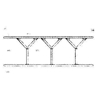
[0009] FIG. 1 is a perspective view of an assembly of impact absorbing
structures formed
from modular rows, in accordance with an embodiment.
[0010] FIG. 2 is a perspective view of a modular row, in accordance with
an
embodiment.
[0011] FIG. 3 is a perspective view of a modular row, in accordance with
an
embodiment.
[0012] FIG. 4 is a plan view of an impact absorbing member having a
branched shape, in
accordance with an embodiment.
[0013] FIG. 5A is a perspective view of impact absorbing structures
including
intersecting arches, in accordance with an embodiment.
[0014] FIG. 5B is a perspective view of an opposing arrangement of the
impact absorbing
structures of FIG. 5A, in accordance with an embodiment.
[0015] FIG. 5C is a perspective view of impact absorbing structures
including
intersecting arches connected by a column, in accordance with an embodiment.
[0016] FIGS. 6A is a cross-sectional view of a helmet including impact
absorbing
structures having a spherical wireframe shape, in accordance with an
embodiment.
[0017] FIG. 6B is a plan view of an impact absorbing structure included
in the helmet of
FIG. 6A, in accordance with an embodiment.
[0018] FIG. 6C is a perspective view of an impact absorbing structure
included in the
helmet of FIG. 6A, in accordance with an embodiment.
[0019] FIGS. 7A is a cross-sectional view of a helmet including impact
absorbing
structures having a jack shape, in accordance with an embodiment.
[0020] FIG. 7B is a plan view of an impact absorbing structure included
in the helmet of
FIG. 7A, in accordance with an embodiment.
- 3a -
CA 3010158 2020-03-26
CA 03010158 2018-06-27
WO 2017/120364
PCT/US2017/012373
100211 FIG. 7C is a perspective view of an impact absorbing structure
included in the
helmet of FIG. 7A, in accordance with an embodiment.
[0022] FIGS. SA is a cross-sectional view of a helmet including impact
absorbing
structures having a bristle shape, in accordance with an embodiment.
[0023] FIG. 8B is a cross-sectional view of an impact absorbing structure
included in the
helmet of FIG. 8A, in accordance with an embodiment.
100241 FIG. 8C is a perspective view of an impact absorbing structure
included in the
helmet of FIG. 8A, in accordance with an embodiment.
[0025] FIG. 9 is a perspective view of an embodiment of an impact absorbing
structure
having a conical structure, in accordance with an embodiment.
[0026] FIG. 10 is a perspective view of an embodiment of an impact
absorbing structure
having a base portion and angled support portions, in accordance with an
embodiment.
[0027] FIG. 11 is a perspective view of an embodiment of an impact
absorbing structure
having a cylindrical member coupled to multiple planar surfaces, in accordance
with an
embodiment.
[0028] FIG. 12 is a perspective view of an embodiment of an impact
absorbing structure
having a base portion to which multiple supplemental portions are coupled, in
accordance
with an embodiment.
[0029] FIG. 13A is a perspective view of an embodiment of a conical impact
absorbing
structure, in accordance with an embodiment.
[0030] FIG. 13B is a cross-sectional view of an alternative impact
absorbing structure, in
accordance with an embodiment.
[0031] FIG. 14 is a side view of an impact absorbing structure having
arched structures,
in accordance with an embodiment.
[0032] FIG. 15 is a perspective and cross-sectional view of an embodiment
of an impact
absorbing structure comprising a cylindrical structure enclosing a conical
structure, in
accordance with an embodiment.
[0033] FIG. 16 is a perspective view of an impact absorbing structure, in
accordance with
an embodiment.
[0034] FIGS. 17A-17C show perspective views of impact absorbing structures
comprising connected support members, in accordance with an embodiment.
- 4 -
CA 03010158 2018-06-27
WO 2017/120364
PCT/US2017/012373
100351 FIGS. 18-20 show example structural groups including multiple
support members
positioned relative to each other with different support members coupled to
each other by
connecting members, in accordance with an embodiment.
DETAILED DESCRIPTION
Modular Helmet
100361 FIG. 1 is a perspective view of an assembly 100 of impact absorbing
structures
formed from modular rows 110, 120, and 130, in accordance with an embodiment.
In
general, a modular row includes an inner surface, an outer surface, and impact
absorbing
structures between the inner surface and the outer surface. The modular row
may further
include a protective layer (c.a., foam) less rigid than the impact absorbing
structures that
encloses a remaining volume between the inner surface and outer surface after
formation of
the impact absorbing structures. When a helmet including the assembly 100 is
worn, the
inner surface is closer to the user's skull than the outer surface.
Optionally, the modular row
includes end surfaces connecting the short edges of the inner surface to the
short edges of the
outer surface. The inner surface, outer surface, and end surfaces form a slice
with two
parallel flat sides and an arc or bow shape on two other opposing sides. The
end surfaces
may be parallel to each other or angled relative to each other. The modular
rows include one
or more base modular rows 110, crown modular rows 120, and rear modular rows
130. The
assembly 100 may include further shells, such as an innermost shell, an
outermost shell, or
both, that secure the modular rows relative to each other and capture the
structure between
the innermost and outermost shells when assembled for durability and impact
resistance.
[0037] The base modular row 110 encircles the wearer's skull at
approximately the same
vertical level as the user's brow. The crown modular rows 120 are stacked
horizontally on
top of the base modular row 110 so that the long edges of the inner and outer
surfaces form
parallel vertical planes. The end surfaces of the crown modular rows 120 rest
on a top plane
of the base modular row. The outer surfaces of the crown modular rows 120
converge with
the outer surface of the base modular row 110 to form a rounded outer shell.
Likewise, the
inner surfaces of the crown modular rows 120 converge with the inner surface
of the base
modular row 110 to form a rounded inner shell. Thus, the crown modular rows
120 and base
modular row 110 form concentric inner and outer shells protecting the wearer's
upper head.
The outer surface of a crown modular row 120 may form a ridge 122 raised
relative to the
rest of the outer surface. The ridge 122 may improve distribution of impact
forces or
- 5 -
CA 03010158 2018-06-27
WO 2017/120364
PCTIUS2017/012373
facilitate a connection between two halves (e.g., left and right halves) of an
outermost layer
of a helmet including assembly 100.
100381 The rear modular rows 130 are stacked vertically under a rear
portion of the base
modular row 110 so that the long edges of the inner and outer surfaces form
parallel
horizontal planes. The inner surface of the topmost rear modular row 130 forms
a seam with
the inner surface of the base modular row 110, and the outer surface of the
topmost rear
modular row 130 forms a seam with the outer surface of the base modular row
110. Thus, the
rear modular rows 130 and the rear portion of the base modular row 110 form
concentric
inner and outer shells protecting the wearer's rear lower head and upper neck.
Modular Row
100391 FIG. 2 is a perspective view of a base modular row 110, in
accordance with an
embodiment. The base modular row 110 includes two concentric surfaces 103
(e.g., an inner
surface and an outer surface), end surfaces, and impact absorbing structures
105.
100401 As illustrated, the impact absorbing structures 105 are columnar
impact absorbing
member is mechanically secured to both concentric surfaces 103. An end of the
impact
absorbing structure 105 may be mechanically secured to a concentric surface
103 as a result
of integral formation, by a fastener, by an adhesive, by an interlocking end
portion (e.g., a
press fa), another technique, or a combination thereof. An end of the impact
absorbing
member is secured perpendicularly to the local plane of the concentric surface
103 in order to
maximize resistance to normal force. However, one or more of the impact
absorbing
members may be secured at another angle to modify the resistance to normal
force or to
improve resistance to torque due to friction between an object and the
outermost surface of a
helmet including assembly100. The critical force that buckles the impact
absorbing member
increases with the diameter of the impact absorbing member and decreases with
the length of
the impact absorbing member.
[0041] Generally, an impact absorbing member has a circular cross section
to eliminate
stress concentration along edges, but other cross-sectional shapes (e.g.,
squares, hexagons)
may be used to simplify manufacturing or modify performance characteristics.
Generally, an
impact absorbing structure is formed from a compliant, yet strong material
such as an
elastomeric substrate such as hard durometer plastic (e.g., polyurethane,
silicone) and may
include a core of a softer material such as open or closed-cell foam (e.g.,
polyurethane,
polystyrene) or fluid (e.g.. air). After forming the impact absorbing members,
a remaining
- 6 -
CA 03010158 2018-06-27
WO 2017/120364
PCTIUS2017/012373
voltune between the concentric surfaces 103 (that is not filled by the impact
absorbing
members) may be filled with a softer material such as foam or a fluid (e.g.,
air).
[0042] The concentric surfaces 103 are curved to form an overall rounded
shape (e.g.,
spherical, ellipsoidal) when assembled into a helmet shape. The concentric
surfaces 103 and
end surfaces 104 may be formed from a material that has properties stiffer
than the impact
absorbing members such as hard plastic, foam, metal, or a combination thereof,
or formed
from the same material as the impact absorbing members. To facilitate
manufacturing of the
base modular row 110, a living hinge technique may be used. The base modular
row 110
may be manufactured as an initially flat modular row, where the long edges of
the concentric
surfaces 103 form two parallel planes. For example, the base modular row 110
is formed by
injection molding the concentric surfaces 103, the end surfaces 104, and the
impact absorbing
structures 105. The base modular row 110 may then be bent to form a living
hinge. The
living hinge may be created by injection molding a thin section of plastic
between adjacent
structures. The plastic is injected into the mold such that the plastic fills
the mold by crossing
the hinge in a direction transverse to the axis of the hinge, thereby forming
polymer strands
perpendicular to the hinge, thereby creating a hinge that is robust to
cracking or degradation.
[0043] FIG. 3 is a perspective view of a modular row 110, in accordance
with an
embodiment. The modular row 110 has a beveled edge with a cross-section that
tapers from
abase to an edge along which the impact absorbing members 305 are secured. For
example,
the modular row 110 has a pentagonal cross section where the impact absorbing
members
305 are mechanically secured along an edge formed opposite the base of the
pentagonal
cross-section. The pentagon has two perpendicular sides extending away from
the base of the
pentagon to two sides that converge at an edge to which the impact absorbing
members 305
are secured. As another example, the modular row 110 has a triangular cross
section (e.g.,
isosceles triangle), and the impact absorbing members 305 are secured along an
edge
opposite the base of the triangular cross-section. Relative to a rectangular
cross-section, the
tapered cross-section reduces the mass to secure the impact absorbing members
305 to the
base of the modular row 110. The base of the modular row 110 is generally
wider than an
impact absorbing member 305 in order to form a shell when assembled with
adjacent
modular rows 110. The general benefit of fonning the base of the rows in this
manner is to
increase moldability of these structures.
- 7 -
CA 03010158 2018-06-27
WO 2017/120364
PCT/US2017/012373
Branched Impact Absorbing Members
100441 FIG. 4 is a plan view of an impact absorbing member 405 having a
branched
shape, in accordance with an embodiment. The impact absorbing member 405
includes a
base portion 410 and two branched portions 415. The base portion 410 and the
branched
portions 415 are joined at one end. Opposite ends of the branched portions 415
are secured
to one of the concentric surfaces 103, and the opposite end of the base
portion 410 is secured
to an opposite one of the concentric surfaces. Varying the angle between the
branched
portions 415 modifies the critical force to buckle the impact absorbing member
405. For
example, increasing the angle between the branched portions 415 decreases the
critical force.
Generally, the angle between the branched portions 415 is between 30 and 120
. The
impact absorbing structure 405 may include additional branched portions 415.
For example,
impact absorbing structure 405 includes three branched portions 415, one of
which is parallel
to the base portion 410.
Impact Absorbing Structures Including., Intersecting Arches
100451 FIG. 5A is a perspective view of impact absorbing structures 505
including
intersecting arches, in accordance with an embodiment. In the illustrated
example, an impact
absorbing structure 505 includes two arches which each form half a circle. The
portions
intersect perpendicular to each other at an apex of the impact absorbing
structure 505.
However, other variations are possible, such as an impact absorbing structure
505 including
three arches intersecting at angles of about 60 , four arches intersecting at
angles of about
45 , or a single arch. In general, having two or more intersecting arches
causes the impact
absorbing structure 505 to have a more uniform rigidity and yield stress from
torques having
different lateral directions relative to a single arch. As another example,
the impact
absorbing structure 505 may form a dome having a uniform resistance to torques
from
different lateral directions, but use of distinct intersecting arches
decreases the weight of the
impact absorbing structure 505. Compared to a dome, the gaps between the
arches in the
impact absorbing structure 505 facilitate injection of foam or another less
rigid material
inside of the impact absorbing structure 505 to further dissipate energy.
[0046] The ends of the arches are mechanically secured to the surface 510,
which may be
a concentric surface 103 of a modular row or an inner or outer shell. The
surface 510 may
form an indentation 515 having a cross-sectional shape corresponding to (and
aligned with) a
projection of the impact absorbing structure 505 onto the surface 510. The
indentation
extends at least partway through the surface 510. For example, the indentation
515 has a
- 8 -
CA 03010158 2018-06-27
WO 2017/120364
PCT1US2017/012373
cross-section of a cross to match the perpendicularly intersecting arches of
the impact
absorbing structure 505 secured above the indentation. When the impact
absorbing structure
505 deforms as a result of a compressive force, the impact absorbing structure
505 may
deflect into the indentation 515. As a result, the impact absorbing member 505
has a greater
range of motion, resulting in absorption of more energy (from deformation) and
slower
deceleration. Without the indentation 515, a compressive force could cause the
impact
absorbing structure 505 to directly contact the surface 510, resulting in a
sudden increase in
stiffness that would limit further gradual deceleration of the impact
absorbing structure 505.
[0047] FIG. 5B is a perspective view of an opposing arrangement of the
impact absorbing
505 structures of FIG. 5A, in accordance with an embodiment. An upper set of
impact
absorbing structures 505 is secured to an outer surface 510A, and a lower set
of impact
absorbing structures 515 is secured to an inner surface 510B. The impact
absorbing
structures 505 may be aligned to horizontally overlap apexes of opposing
impact absorbing
structures 505, or the impact absorbing structures 505 may be aligned to
horizontally offset
apexes of impact absorbing structures 505 on the outer surface 510A and inner
surface 510B.
In the vertically aligned arrangement, the distance between the inner and
outer surfaces is
increased, which provides more room for deformation of the impact absorbing
structures 505
to absorb energy from a collision. In the offset arrangement, the distance
between the inner
and outer surfaces 510 is reduced, and the area of contact between oppositely
aligned impact
absorbing structures 505 is increased. Although the outer surface 510A and the
inner surface
I OB are illustrated as being planar, they may be curved, as in a modular row
or a concentric
shell arrangement. In such a case, the outer surface 510A may include more
impact
absorbing structures 505 than the inner surface 510B, or the impact absorbing
structures 505
of the outer surface 5I0A may be horizontally enlarged relative to those on
the inner surface
510B.
[0048] FIG. 5C is a perspective view of impact absorbing structures 555
including
intersecting arches 560 connected by a column 565, in accordance with an
embodiment. The
intersecting arches 560 may be intersecting arches, such as the impact
absorbing structures
505. The column 565 may be similar to the impact absorbing members 105 and
305. As
illustrated, the opposite ends of a column 565 are perpendicularly connected
to two vertically
aligned intersecting arches 560. Because the columns 565 are subject to
different types of
deformation relative to the intersecting arches (e.g., buckling and
deflection), the impact
absorbing structure 555 may have two or more critical forces that result in
deformation of
- 9 -
CA 03010158 2018-06-27
WO 2017/120364
PCT/US2017/012373
different components of the impact absorbing structure 555. hi this way, the
impact
absorbing structure 555 may dissipate energy from a collision in multiple
stages through
multiple mechanisms. In other embodiments, the impact absorbing structures 505
and 555
may include any of the impact absorbing structures described with respect to
FIGS. 6A
through 8C.
Packed Impact Absorbing Structures
[00491 FIGS. 6A is a cross-sectional view of a helmet 600 including impact
absorbing
structures 615 having a spherical wireframe shape, in accordance with an
embodiment. FIG.
6B is a plan view of the impact absorbing structure 615 included in the helmet
600, in
accordance with an embodiment. FIG. 6C is a perspective view of the impact
absorbing
structure 615 included in the helmet 600, in accordance with an embodiment.
100501 The helmet 600 includes an outer shell 605, an inner shell 610, and
impact
absorbing structures 615 disposed between the outer shell 605 and the inner
shell 610. The
impact absorbing structures 615 are formed from perpendicularly interlocked
rings that
together form a spherical wireframe shape. Although the illustrated impact
absorbing
structures 615 include three mutually orthogonal rings, other structures are
possible. For
example, the number of longitudinal rings may be increased to improve the
uniformity of the
impact absorbing structure's response to forces from different directions.
However,
increasing the number of rings increases the weight of the impact absorbing
structure 615 and
decreases the space between the rings, which hinders filling an internal
volume of the impact
absorbing structure 615 with a less rigid material such as foam.
100511 The helmet 600 further includes a facemask 620, which protects a
face of the
wearer while allowing visibility, and vent holes 625, which improve user
comfort by enabling
air circulation to the user's skin. For example, the helmet 600 forms the vent
holes 625 near
the user's cars to improve propagation of sound waves. The vent holes 625
further serve to
reduce moisture and sweat accumulating in the helmet 600. In some embodiments,
the
helmet includes a screen or mesh (e.g., from metal wire) placed over a vent
hole 625 to
reduce penetration by particles (e.g., soil, sand, snow) and to prevent
penetration by blunt
objects during collisions.
100521 FIG. 7A is a cross-sectional view of a helmet 700 including impact
absorbing
structures 715 having a jack shape, in accordance with an embodiment. FIG. 7B
is a plan
view of the impact absorbing structure 715 included in the helmet 700, in
accordance with an
- 10 -
CA 03010158 2018-06-27
WO 2017/120364
PCTIUS2017/012373
embodiment. FIG. 7C is a perspective view of the impact absorbing structure
715 included in
the helmet 700, in accordance with an embodiment.
[0053] The helmet 700 includes an outer shell 605, an inner shell 610,
impact absorbing
structures 715 disposed between the outer shell 605 and the inner shell 610, a
face mask 620,
and vent holes 625. As illustrated, an impact absorbing structure 715 has a
jack shape
formed by three orthogonally intersecting bars, which connect a central point
to faces of an
imaginary cube enclosing the impact absorbing structure 715. Alternatively,
the impact
absorbing structures may include additional bars intersecting at a central
point, such as bars
that connect the central point to faces of an enclosing tetrahedron or
octahedron. Compared
to impact absorbing structures with a column shape, the impact absorbing
structures 715 may
have increased resistance to forces from multiple directions, particularly
torques due to
friction in a collision.
100541 The impact absorbing structures 615 or 715 may be mechanically
secured to the
outer shell 605, the inner shell 610, or both. However, mechanically securing
the impact
absorbing structures 615 or 715 increase manufacturing complexity and may be
obviated by
filling the volume between the outer shell 605 and inner shell 610 with
another material.
This other material may secure the impact absorbing structures 615 relative to
each other and
the inner and outer shells, which prevents bothersome rattling.
100551 FIGS. 8A is a cross-sectional view of a helmet 800 including impact
absorbing
structures 815 having a bristle shape, in accordance with an embodiment. FIG.
8B is a plan
view of the impact absorbing structure 815 included in the helmet 800, in
accordance with an
embodiment. FIG. 8C is a perspective view of the impact absorbing structure
815 included in
the helmet 800, in accordance with an embodiment.
[0056] The helmet 800 includes an outer shell 605, an inner shell 610,
impact absorbing
structures 815 disposed between the outer shell 605 and the inner shell 610, a
face mask 620,
and vent holes 625. As illustrated, an impact absorbing structure 815 has a
bristle shape with
multiple bristles arranged perpendicular to outer shell 605, inner shell 610,
or both. The
impact absorbing structure 815 further includes holes having a same diameter
as the bristles.
As illustrated, the holes and bristles of the impact absorbing structure are
arranged in an array
structure with the bristles and holes alternating across rows and columns of
the array. The
impact absorbing structure may include a base pad secured to the shell 605 or
610. The base
pad secures the bristles and forms the holes. Alternatively, the shells 605
and 610 serve as
base structures that secure the bristles and forms the holes. Impact absorbing
structures 815
- 11 -
CA 03010158 2018-06-27
WO 2017/120364
PCT/US2017/012373
on the shells 605 and 610 are aligned oppositely and may be offset so that
bristles of an upper
impact absorbing structure 815 are aligned with holes of the lower impact
absorbing structure
815, and vice versa. In this way, the ends of bristles may be laterally
secured when the
opposing impact absorbing structures 815 are assembled between the outer shell
605 and the
inner shell 610.
100571 In some embodiments, the impact absorbing structures 615, 715, or
815 are
secured in a ridge that protrudes from an outer shell of the helmet 100 (e.g.,
like a mohawk).
hi this way, the ridge may absorb energy from a collision before the force is
transmitted to
the outer shell of the helmet 100.
Additional Impact Absorbing Structures
100581 FIG. 9 is a perspective view of an embodiment of an impact absorbing
structure
910 having a conical structure. In the example shown by FIG. 9, the impact
absorbing
structure 910 has a circular base 915 coupled to a circular top 920 via a
conical structure 925.
As shown in FIG. 9, a portion of the conical structure 925 coupled to the
circular base 915
has a smaller diameter than an additional portion of the conical structure 925
coupled to the
circular top 920 of the impact absorbing structure 910. In various
embodiments, the interior
of the conical structure 925 is hollow. Alternatively, a less rigid material,
such as foam, may
be injected into the interior of the conical structure 925 to further
dissipate energy from an
impact. In various embodiments, the circular base 915 is configured to be
coupled to an
inner shell of a helmet, while the circular top 920 is configured to be
coupled to an outer shell
of a helmet, such as the helmet described above in conjunction with FIGS. 6A,
7A, and 8A
Alternatively, the circular base 915 is configured to be coupled to an outer
shell of a helmet,
while the circular top 920 is configured to be coupled to an inner shell of a
helmet, such as
the helmet described above in conjunction with FIGS. 6A, 7A, and 8A
100591 FIG. 10 is a perspective view of an embodiment of an impact
absorbing structure
1005 having abase portion 1010 and angled support portions 10I5A, 1015B (also
referred to
individually and collectively using reference number 1015). The impact
absorbing structure
405 includes a base portion 410 and two branched portions 415. The base
portion 1010 is
coupled to each of the concentric surfaces 103 further described above in
conjunction with
FIG. 2, while a support portion 1015A has an end coupled to the base portion
1010 and
another end coupled to one or the concentric surfaces 103. In the example
shown by FIG. 10,
each base portion 1010 has two support portions 1015A coupled to the base
portion 1010 and
to one of the concentric surfaces 103 and also has two additional support
portions 1015B
- 12 -
coupled to the base portion 1010 and to the other concentric surface 103.
However, in other
embodiments, the base portion 1010 has any suitable number of support portions
1015
coupled to the base portion 1010 and to one of the concentric surfaces 103. In
some
embodiments, the base portion includes different numbers of support portions
1015 coupled
to the base portion and to a concentric surface 103 and coupled to the other
concentric surface
103.
[0060] A support portion 1015 is coupled to the base portion 1010 at an
angle and is
coupled to a concentric surface 103 at an additional angle. In various
embodiments, the angle
equals the additional angle. Varying the angle at which the support portion
1015 is coupled
to the base portion 1010 or the additional angle at which the support portion
1015 is coupled
to the concentric surface 103 modifies a critical force that, when applied,
cause the impact
absorbing member 1005 to buckle.
[0061] FIG. 11 is a perspective view of an embodiment of an impact
absorbing structure
1105 having a cylindrical member coupled to multiple planar surfaces 1115A,
1115B (also
referred to individually and collectively using reference number 1115). In the
example
shown by FIG. 11, the cylindrical member has a vertical portion 1112 having a
height and
having a circular base 1110 at one end. At an opposite end of the vertical
portion 1112 from
the circular base 110, multiple planar surfaces 1115A, 1115B are coupled to
the vertical
portion 1112. Different planar surfaces 1115 are separated by a distance 1120.
For example,
FIG. 11 shows planar surface 1115A separated from planar surface 1115B by the
distance
1120. In various embodiments, each planar surface 1115 is separated from an
adjacent planar
surface 1115 by a common distance 1120; alternatively, different planar
surfaces 1115 are
separated from other planar surfaces 1115 by different distances 1120. Each
planar surface
1115 has a width 1125, while FIG. 11 shows an embodiment where the width 1125
of each
planar surface 1115 is the same, different planar surfaces 1115 may have
different widths in
1125 in other embodiments. The planar surfaces 1115 are coupled to the
opposite end of the
vertical portion 1112 of the cylindrical member than the circular base 1110
around a
circumference of the cylindrical member. Additionally, the circular base 1110
is configured
to be coupled to an outer shell of a helmet, while ends of the planar surfaces
1115A, 1115B
not coupled to the vertical portion of the cylindrical member are configured
to be coupled to
an inner shell of a helmet, such as the helmet described above in conjunction
with FIGS. 6A,
7A, and 8A. Alternatively, the circular base 1110 is configured to be coupled
to an inner
shell of a helmet, while ends of the planar surfaces 1115A, 1115B not coupled
to the vertical
- 13 -
CA 3010158 2020-03-26
CA 03010158 2018-06-27
WO 2017/120364
PCT1US2017/012373
portion of the cylindrical member are configured to be coupled to an outer
shell of a helmet,
such as the helmet described above in conjunction with FIGS. 6A, 7A, and 8A In
other
embodiments, the circular base 1110 is configured to be coupled to a
concentric surface 103
and the ends of the planar surfaces 1115A, 1115B not coupled to the vertical
portion of the
cylindrical member are configured to be coupled to another concentric surface
103.
100621 FIG. 12 is a perspective view of an embodiment of an impact
absorbing structure
1205 having a base portion 1210 to which multiple supplemental portions 1215A,
1215B
(also referred to individually and collectively using reference number 1215)
are coupled.
Support portions 1220A, 1220B (also referred to individually and collectively
using reference
number 1220) are coupled to a concentric surface 103 and to a supplemental
portion 1215A,
1215B. As shown in FIG. 12, an end of a supplemental portion 1215A is coupled
to the base
portion 1210, while an opposing end of the supplemental portion 1215A is
coupled to a
support portion 1220A. The support portion 1220A has an end coupled to the
opposing end
of the supplemental portion 1215A, while another end of the support portion
1220A is
coupled to a concentric surface 103. In various embodiments, an end of the
base portion
1210 and the other ends of the support portions 1220 are each coupled to a
common
concentric surface 103, while an opposing end of the base portion 1210 is
coupled to a
different concentric surface 103.
[00631 Any number of supplemental portions 1215 may be coupled to the base
portion
1210 of the impact absorbing structure in various embodiments. Additionally,
the
supplemental portions 1215 are coupled to the base portion 1210 at an angle
relative to an
axis parallel to the base portion 1210. In some embodiments, each supplemental
portion
1215 is coupled to the base portion 1210 at a common angle relative to the
axis parallel to the
base portion 1210. Alternatively, different supplemental portions 1215 are
coupled to the
base portion 1210 at different angles relative to the axis parallel to the
base portion 1210.
Similarly, each support portion 1220 is coupled to a supplemental portion 1215
at an angle
relative to an axis parallel to the supplemental portion 1215. In some
embodiments, each
support portion 1220 is coupled to a corresponding supplemental portion 1215
at a common
angle relative to the axis parallel to the supplemental portion 1215.
Alternatively, different
support portions 1220 are coupled to a corresponding supplemental portion 1215
at different
angles relative to the axis parallel to the corresponding supplemental portion
1215.
100641 FIG. 13A is a perspective view of an embodiment of a conical impact
absorbing
structure 1305. The conical impact absorbing structure 1305 has a circular
base 1315 and an
- 14 -
additional circular base 1320 that has a smaller diameter than the circular
base 1315. A
vertical member 1310 is coupled to the circumference of the circular base 1315
and to a
circumference of the additional circular base 1320. Hence, a width of the
vertical member
1310 is larger nearer to the circular base 1315 and is smaller nearer to the
additional circular
base 1320. The circular base 1315 is configured to be coupled to a concentric
surface 103,
while the additional circular base 1320 is configured to be coupled to an
additional concentric
surface 103. In the example shown by FIG. 13A, the vertical member 1310 is
hollow.
Alternatively, a less rigid material, such as foam, may be injected into the
interior of the
vertical member 1310 to further dissipate energy from an impact.
[0065] FIG. 13B is a cross-sectional view of an alternative impact
absorbing structure
1330. In the example shown by FIG. 13B, the alternative impact absorbing
structure 1330
has a circular base 1340 and an additional circular base 1345 that each have a
common
diameter. A vertical member 1350 is coupled to the circular base 1340 and to
the additional
circular base 1345. Because the diameter of the circular base 1340 equals the
diameter of the
additional circular base 1345, the vertical member 1350 has a uniform width
between the
circular base 1340 and the additional circular base 1345. In the example of
FIG. 13B, the
vertical member 1350 is hollow. Alternatively, a less rigid material, such as
foam, may be
injected into the interior of the vertical member 1350 to further dissipate
energy from an
impact. The circular base 1345 is configured to be coupled to a concentric
surface 103, while
the additional circular base 1350 is configured to be coupled to an additional
concentric
surface 103.
[0066] FIG. 14 is a side view of an impact absorbing structure 1405
having arched
structures 1410A, 1410B. In the example shown by FIG. 14, the impact absorbing
structure
1405 has an arched structure 1410A coupled to a concentric surface 103 at an
end and
coupled to another concentric surface 103 at an opposing end. Similarly, an
additional arched
structure 1410B is coupled to the concentric surface 103 at an end, while an
opposing end of
the additional arched structure 1410B is coupled to the other concentric
surface 103. A
bracing member 1415 is positioned in a plane parallel to the concentric
surface 103 and the
other concentric surface 103. An end of the bracing member 1415 is coupled to
the arched
structure 1410A, while an opposing end of the bracing member 1415 is coupled
to the
additional arched structure 1410B. In various embodiments, the end of the
bracing member
1415 is coupled to the arched structure 1410A at an apex of the arched
structure 1410B
relative to an axis perpendicular to the bracing member 1415. Similarly, the
opposing end of
- 15 -
CA 3010158 2020-03-26
CA 03010158 2018-06-27
WO 2017/120364
PCT/US2017/012373
the bracing member 1415 is coupled to the additional arched structure 1410B at
an apex of
the additional arched structure 1410B relative to the axis perpendicular to
the bracing
member 1415. However, in other embodiments, the bracing member 1415 may be
coupled to
any suitable portions of the archcd structure 1410A and the additional arched
structure 1410B
along a plane parallel to the concentric surface 103 and the other concentric
surface 103.
100671 Additionally, a supporting structure 1420A is coupled to a portion
of a surface of
the bracing member 1415 and to an additional portion of the surface of the
bracing member
1415. Similarly, an additional supporting structure 1420B is coupled to a
portion of an
additional surface of the bracing member 1415 that is parallel to the surface
of the bracing
member 1415 and to an additional portion of the additional surface of the
bracing member
1415. As shown in FIG. 14, the supporting structure 1420A is arched between
the portion of
the surface of the bracing member 1415 and the additional portion of the
surface of the
bracing member 1415. Similarly, the additional supporting structure 1420B is
arched
between the portion of the additional surface of the bracing member 1415 and
the additional
portion of the additional surface of the bracing member 1415.
100681 FIG. 15 is a perspective and cross-sectional view of an embodiment
of an impact
absorbing structure 1505 comprising a cylindrical structure 1510 enclosing a
conical
structure 1515. In the example shown by FIG. 15, the impact absorbing
structure 1505 has a
cylindrical structure 1510 having an interior wall 1535 and an exterior wall.
The cylindrical
structure 1510 encloses a conical structure 1515 having a circular base1520 at
one end and an
additional circular base 1525 at an opposing end. In various embodiments. the
cylindrical
structure 1510 and the conical structure 1515 each have different durometers,
so the
cylindrical structure 1510 and the conical structure 1515 have different
hardnesses.
Alternatively, the cylindrical structure 1510 and the conical structure 1515
have a common
hardness. The additional circular base 1525 has a smaller diameter than the
circular base
1520. Additionally, the interior wall 1535 of the cylindrical structure 1510
tapers from a
portion of the cylindrical structure 1510 nearest the additional circular base
1525 of the
conical structure 1515 to being coupled to a circumference of the circular
base 1520 of the
conical structure 1515. In some embodiments, such as shown in FIG. 15, a
height of the
conical structure 1515 is greater than a height of the cylindrical structure
1510, so the
additional circular base 1525 of the conical structure 1515 protrudes above
the cylindrical
structure 1510. Alternatively, the height of the conical structure 1515 equals
the height of the
cylindrical structure 1510, so a top of the cylindrical structure 1510 is in a
common plane as
- 16 -
CA 03010158 2018-06-27
WO 2017/120364
PCT/US2017/012373
the additional circular base 1525 of the conical structure 1515.
Alternatively, the height of
the conical structure 1515 is less than the height of the cylindrical
structure 1510. As an
additional example, the conical structure 1515 and the cylindrical structure
1510 have equal
heights. In various embodiments, the circular base 1520 of the conical
structure 1515 is
configured to be coupled to an inner shell of a helmet, while the additional
circular base 1525
of the conical structure 1515 is configured to be coupled to an outer shell of
a helmet, such as
the helmet described above in conjunction with FIGS. 6A, 7A, and 8A.
Alternatively, the
circular base 1520 of the conical structure 1515 is configured to be coupled
to an outer shell
of a helmet, while the additional circular base 1525 of the conical structure
1515 is
configured to be coupled to an inner shell of a helmet, such as the helmet
described above in
conjunction with FIGS. 6A, 7A, and 8A
[0069] FIG. 16 shows an embodiment of an impact absorbing structure 1605.
In the
example shown by FIG. 16, the impact absorbing structure 1605 is a surface
that undulates in
a plane perpendicular to a plane including a concentric surface 103 and is
coupled at one end
to the concentric surface 103 and is coupled at an opposing end to an
additional concentric
surface 103. For example, the impact absorbing structure 1605 has a sinusoidal
cross section
in a plane parallel to the plane including the concentric surface 103.
However, in other
embodiments, the impact absorbing structure 1605 has any suitable profile in a
cross section
along the plane parallel to the plane including the concentric surface 103.
[0070] FIGS. 17A-17C show perspective views of impact absorbing structures
1700A,
1700B, 1700C comprising connected support members 1705, 1710. Each support
member
1705, 1710 has an end configured to be coupled to a concentric surface 103 and
an opposing
end configured to be coupled to another concentric surface 103. A support
member 1705 is
coupled to the other support member 1710 by a connecting element that is in a
plane
perpendicular to a plane including the concentric surface 103, or in a plane
perpendicular to
another plane including the other concentric surface 103. In the example of
FIG. 17A, an
impact absorbing structure 1700A includes a rectangular structure 1715A
connecting the
support member 1705 to the other support member 1710 and perpendicular to the
concentric
surface 103 and to the other concentric surface 103. In various embodiments,
an end of the
rectangular structure 1715A is coupled to the concentric surface 103, while an
opposite end
of the rectangular structure 1715A is coupled to the other concentric surface
103.
100711 FIG. 17B shows an impact absorbing structure 1700B including an
arched
structure 1715B connecting the support member 1705 to the other support member
1710.
- 17 -
CA 03010158 2018-06-27
WO 2017/120364
PCTIUS2017/012373
The arched structure 1715B is perpendicular to the concentric surface 103 and
to the other
concentric surface 103 and is arched in a plane that is parallel to the
concentric surface 103
and to the other concentric surface 103. In various embodiments, an end of the
arched
structure 1715B is coupled to the concentric surface 103, while an opposite
end of the arched
structure 1715B is coupled to the other concentric surface 103.
100721 FIG. 17C shows an impact absorbing structure 1700B including an
undulating
structure 1715C connecting the support member 1705 to the other support member
1710.
The undulating structure 1715C is perpendicular to the concentric surface 103
and to the
other concentric surface 103 and includes multiple arcs in a plane that is
parallel to the
concentric surface 103 and to the other concentric surface 103. For example,
the undulating
structure 1715C has a sinusoidal cross section in a plane parallel to the
plane including a
concentric surface 103. In various embodiments, an end of the undulating
structure 1715C is
coupled to the concentric surface 103, while an opposite end of the undulating
structure
1715C is coupled to the other concentric surface 103.
100731 While FIGS. 17A-17C show examples of impact absorbing structures
where a pair
of support members are coupled to each other by a connecting member, any
number of
support members may be positioned relative to each other and different pairs
of the support
members connected to each other by connecting members to form structural
groups. FIGS.
18-20 show example structural groups including multiple support members
positioned
relative to each other with different support members coupled to each other by
connecting
members. FIG. 18 shows an impact absorbing structure 1800 having a central
support
member 1805 coupled to three radial support members 1810A, 1810B, 1810C that
are
positioned along a circumference of a circle having an origin at the central
support member
1805. The central support member 1800 is coupled to radial support member
1810A by
connecting member 1815A and is coupled to radial support member 1810B by
connecting
member 1815B. Similarly, the central support member 1800 is coupled to radial
support
member 1810C by connecting member 1815C. While FIG. 18 shows an example where
the
connecting member 1815A, 1815B, 1815C are rectangular, while in other
embodiments, the
connecting members 1815A, 1815B, 1815C may be arched structures or undulating
structures
as described in FIGS. 17B and 17C or may have any other suitable cross
section.
100741 FIGS. 19A and 19B show perspective views of an impact absorbing
structure
1900A, 1900B comprising six support members coupled to each other by
connecting
members to form a hexagon. In the example shown by FIG. 19Aõ the impact
absorbing
- 18 -
CA 03010158 2018-06-27
WO 2017/120364
PCTIUS2017/012373
structure 1900A has pairs of support members coupled to each other via
rectangular
connecting members to form a hexagon. The impact absorbing structure 1900B
shown by
FIG. 19B has pairs of support members coupled to each other via undulating
support
members to form a hexagon.
[0075] FIG. 20 is a perspective view of an impact absorbing structure 2000
comprising
rows of offset support members coupled together via connecting members. In the
example of
FIG. 20, support members are positioned in multiple parallel rows 2010, 2020,
2030, 2040,
with support members in a row offset from each other so support members in
adjacent rows
are not in a common plane parallel to the adjacent rows. For example, support
members in
row 2010 are positioned so they are not in a common plane parallel to support
members in
row 2020. As shown in the example of FIG. 20, a support member in row 2020 is
positioned
so it is between support members in row 2010. Connecting members connect
support
members in a row 2010 to support members in an adjacent row 2020. In some
embodiments,
support members in a row 2010 are not connected to other support members in
the row 2010,
but are connected to a support member in an adjacent row 2020 via a support
member 2015.
100761 Although described throughout with respect to a helmet, the impact
absorbing
structures described herein may be applied with other garments such as
padding, braces, and
protectors for various joints and bones.
Additional Configuration Considerations
[0077] The foregoing description of the embodiments of the disclosure has
been
presented for the purpose of illustration; it is not intended to be exhaustive
or to limit the
disclosure to the precise forms disclosed. Persons skilled in the relevant art
can appreciate
that many modifications and variations are possible in light of the above
disclosure.
[0078] The language used in the specification has been principally selected
for
readability and instructional purposes, and it may not have been selected to
delineate or
circumscribe the inventive subject matter. It is therefore intended that the
scope of the
disclosure be limited not by this detailed description, but rather by any
claims that issue on an
application based hereon. Accordingly, the disclosed embodiments are intended
to be
illustrative, but not limiting, of the scope of the disclosure.
- 19 -