Note: Descriptions are shown in the official language in which they were submitted.
Disinfection Cap for IV Needleless Connectors
Field of the Invention
[0001] Generally, exemplary embodiments of the present invention relate to
the fields of
medical disinfection caps, and in particular disinfection caps for uses with
IV needleless connectors.
Background of the Invention
[0002] In order to decrease Catheter-related bloodstream infection (CRBSI)
cases, which are
high impact events with high costs and high associated mortality, needleless
connector disinfection Cap
space continues to grow at a rapid pace since disinfection caps were
originally disclosed in U.S. Patent
Publication No. 2007/011233 which issued as U.S. Patent No. 8,740,864, and
introduced on the
market. Disinfection caps such as those disclosed in the U.S. Patent No.
8,740,864 are illustrated in
Figures lA and 1B, where cap 1 includes a disinfecting pad 2 and a lid 3, and
cap 4 includes a
disinfecting pad 5 and lid 7, as well as threads 6 on its inner circumference
8 to interlock with
needleless connector hub. As illustrated in Figure 2, a plurality of
disinfection caps 23, such as cap 1
and/or cap 7 of Figures JA and 1B, can be disposed on a strip 22, which
includes an opening 24 for
hanging strip 22 on an IV pole. In an IV pole hanging device 21, strip 22 can
serve as a common lid,
1
Date recue/Date received 2023-05-08
for example having the same function as lid 3 and/or 7, for caps 23 disposed
thereon, such that
removed cap 25 is ready for immediate placement on a needleless connector.
[0003] Disinfection caps have been added to the Society for Healthcare
Epidemiology of
America (SHEA) guidelines and early indications are that caps will also be
incorporated into the 2016
Infusion Nurses Standards (INS) guidelines.
[0004] In developed markets, when utilizing an IV catheter, a needleless
connector will
typically be used to close off the system and then subsequently accessed to
administer medication or
other necessary fluids via the catheter to the patient. INS Standards of
Practice recommend the use of a
needleless connector and state that it should be "consistently and thoroughly
disinfected using alcohol,
tincture of iodine or chlorhexidine gluconate/a1cohol combination prior to
each access." The
disinfection of the needleless connector is ultimately intended to aid in the
reduction of bacteria that
could be living on the surface and possibly lead to a variety of catheter
related complications including
the CRBSI events described before. Nurses will typically utilize a 70% IPA
alcohol pad to complete
this disinfection task by doing what is known as "scrubbing the hub." However,
compliance to this
practice is typically very low. In addition to a lack of compliance to
"scrubbing the hub", it has also
been noted through clinician interviews that there is often a variation in
scrub time, dry time and the
number of times the needleless connector is scrubbed.
[0005] Cap technology presents significant challenges associated with
needleless connectors.
All of the disinfection caps currently on the market contain 70% isopropyl
alcohol as the active
disinfection ingredient. However, many of the needleless connector designs use
Acrylic or similar
material for the main housing. Acrylic has mild to poor chemical stability
resistance to isopropyl
alcohol over prolonged exposure times. Hence the isopropyl alcohol can cause
chemical breakdown
damage of Acrylic in the form of discoloration and/or cracking of the
needleless connector material. In
2
Date recue/Date received 2023-05-08
addition, nearly all of the needleless connectors on the market use silicone
material for the fluid path
valve designs. Silicone materials have a mild to poor chemical stability
resistance to isopropyl alcohol
over prolonged exposure times. This can lead to swelling of the silicone parts
which can then cause the
needleless connector valve to stick closed and/or fail to close (causing blood
leakage). Additionally,
increased silicone swelling could increase stress on the connector housing
which could amplify the
outer Acrylic needleless connector housing cracking issues.
[0006] Conventionally, in order to address the issue of isopropyl alcohol
chemical
incompatibility with needleless connector materials, disinfection cap having
alcohol vents (such as
those described in US Patents Nos. 8,206,514; 7,985,302; and 7,780, 794) have
been developed. Such
vents allow a cap to vent the disinfecting alcohol away from the needleless
connectors faster in
comparison to caps currently on the market which do not have such vents.
Hence, alcohol venting can
reduce chemical damage to the needleless connector materials.
[0007] However, such conventional vent features have some significant
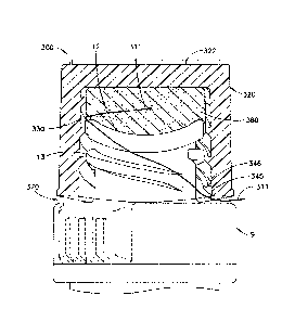
drawbacks. One
drawback is that the venting feature can require forming dedicated venting
holes in the cap, or be
dependent on a significant undercut reign and/or an assembly of two molded
parts, main cap housing
and a thread ring, as described for example in U.S. Patent No. 8,206,514. Such
conventional venting
feature drives a cap design to require separate molding of the parts. These
separate parts must then be
assembled, then welded or adhesively bonded together. Accordingly, such a
design has inherently
higher tooling costs, manufacturing complexity, and production costs in
comparison to for example a
single shot molded cap housing design.
[0008] Hence if a disinfection cap could be developed with a venting
feature that avoids
undercuts it would eliminate the costly assembly and welding steps. In
addition, if a disinfection cap
3
Date recue/Date received 2023-05-08
could be developed with increased venting performance, it may further reduce
needleless connector
failures.
Summary of the Invention
[0009] In accordance with an aspect of the present invention, a
disinfection cap comprises a
housing including a closed top, an essentially cylindrical sidewall, and an
open bottom formed by said
sidewall with an opening to an inner cavity within said housing for receiving
a tip including a mating
feature of said needleless connector. A disinfection sponge can be configured
within the inner cavity,
with a removable cover sealing the opening to the inner cavity to seal the
sponge within the inner
cavity prior to use of the cap. The inner cavity comprises at least one thread
on an inner sidewall
surface of the sidewall. The cap thread is sufficient to interlock with the
mating feature of the
needleless connector, the cap thread does not correspond to the mating feature
of the needleless
connector.
[0010] In accordance with another aspect of the present invention, at
least one of a major
diameter, a minor diameter, a pitch, a thread section profile, and a number of
threads of the cap thread
does not correspond to the mating feature of the needleless connector.
[0011] In accordance with another aspect of the present invention, a
portion of the side wall
forming the open bottom comprises an inner sidewall surface forming the
opening to the inner cavity
such that the open bottom does not form an airtight seal with an outer surface
of the needleless
connector when the needleless connector is securely engaged with the housing.
[0012] In accordance with another aspect of the present invention, the
open bottom formed by
said sidewall of the housing is not flat such that an exit space exists
between a flat surface and the
bottom of the housing, whereby venting of the disinfection sponge occurs
through the opening to the
4
Date recue/Date received 2023-05-08
inner cavity, essentially around an outside of the mating feature of the
needleless connector and via the
exit space to an outside of the cap housing.
[0013] In accordance with another aspect of the present invention, the
open bottom formed by
the sidewall of the housing includes an irregular bottom inner sidewall
surface with one or more divots
configured such that the opening to the inner cavity does not form an airtight
seal with an outer surface
of the needleless connector, whereby venting of the disinfection sponge occurs
through the opening to
the inner cavity, essentially around an outside of the mating feature of the
needleless connector and via
at least one of the divots to an outside of the cap housing.
[0014] In accordance with another aspect of the present invention, the
housing comprises a
flared lower portion formed at the open bottom comprising one or more divots
regularly or randomly
spaced along bottom inner sidewall surface defining the opening to the inner
cavity.
[0015] In accordance with another aspect of the present invention, the cap
thread comprises an
extended portion extending below the open bottom formed by the sidewall such
that an escape space
exists between a surface of top portion of the needless connector and the open
bottom when the cap
thread interlocks with the needleless connector such that the extended portion
contacts top portion of
the needleless connector, whereby venting of the disinfection sponge occurs
through the opening to the
inner cavity, essentially around an outside of the mating feature of the
needleless connector and via the
escape space to an outside of the cap housing.
[0016] In accordance with another aspect of the present invention, a
portion of the side wall
forming the open bottom comprises a flared bottom portion having an inner
sidewall surface forming
the opening to the inner cavity such that the open bottom does not form an
airtight seal with an outer
surface of the needleless connector when the needleless connector is securely
engaged with the
housing, whereby venting of the disinfection sponge occurs through the opening
to the inner cavity,
essentially around an outside of the mating feature of the needleless
connector, and between the inner
Date recue/Date received 2023-05-08
wall surface of the flared bottom portion and the outer surface of the
needleless connector to an
outside of the cap housing.
[0017] In accordance with another aspect of the present invention, the
open bottom formed by
the sidewall of said housing is essentially flat.
[0018] In accordance with another aspect of the present invention, the
open bottom formed by
said sidewall of the housing is not flat such that an exit space exists
between a flat surface and the
bottom of said housing.
[0019] In accordance with another aspect of the present invention, the
inner cavity comprises
an upper region terminating in a closed top, and a lower region terminating in
an opening to the inner
cavity, the lower region comprises the cap thread, and the upper region
comprises protrusions into the
inner cavity configured to contact and/or engage the sponge.
[0020] In accordance with another aspect of the present invention, the
sidewall comprises an
inner sidewall surface including a plurality of sections between the cap
thread, each of the sections
having a slope with respect to the longitudinal axis of the housing of the
cap. At least one of the
sections forming the open bottom expands away from the longitudinal axis to
form the flared bottom
portion.
[0021] In accordance with another aspect of the present invention, the
inner cavity comprises
an upper region terminating in a closed top, and a lower region terminating in
the opening to the inner
cavity. The inner sidewall surface comprises a transition section having a
linear or curved surface
where the inner sidewall surface transitions from the lower region to the
upper region such that cross
sectional area at bottom of the transition section in the lower region is
greater than cross sectional area
at top of the transition section in the upper region.
[0022] In accordance with another aspect of the present invention, the
sponge is secured from
being displaced into the upper region when the cap thread interlocks with the
mating feature of the
6
Date recue/Date received 2023-05-08
needleless connector, such that the sponge maintains contact with the
needleless connector and remains
away from an inner surface of the closed top.
[0023] In accordance with another aspect of the present invention, the
opening to the inner
cavity formed by the inner sidewall surface of the bottom portion is
essentially circular and comprises
an opening diameter, and the opening diameter is larger than a flange diameter
of the needless
connector, such that said opening diameter causes a venting gap between the
inner sidewall surface of
the housing and the needless connector, whereby the opening to the inner
cavity comprises the venting
gap and the venting of the disinfection sponge occurs through the opening to
the inner cavity,
essentially around the outside of the mating feature of the needleless
connector and via the venting gap,
to the outside of the cap housing.
[0024] In accordance with another aspect of the present invention, the
sidewall comprises the
inner sidewall surface in the lower region including a plurality of sections
between the cap thread, each
of the sections having essentially the same slope with respect to the
longitudinal axis of the housing of
the cap, and at least one of the sections forming the open bottom, the at
least one of the sections
expanding away from the longitudinal axis to form the flared bottom portion.
[0025] In accordance with another aspect of the present invention, at
least one cap thread on the
inner sidewall surface of the sidewall comprises a protrusion formed on a
least a portion of the cap
thread to facilitate the interlocking with the mating feature of the
needleless connector.
[0026] In accordance with another aspect of the present invention, at
least a portion of at least
one cap thread comprises a non-engaging portion that does not engage the
mating feature of the
needleless connector.
[0027] In accordance with another aspect of the present invention, the cap
thread comprises at
least one interlocking portion formed on a least a portion of the cap thread
to facilitate interlocking
7
Date recue/Date received 2023-05-08
with the mating feature of the needleless connector, and at least one non-
engaging portions that does
not engage the mating feature of the needleless connector.
[0028] In accordance with another aspect of the present invention, a
device comprising a strip,
and a plurality of disinfection caps according to exemplary embodiments of the
present invention
disposed on said strip.
[0029] In accordance with an exemplary implementation of the present
invention, the strip of
the device is essentially flat and comprises a plurality of sections separated
by perforations in the strip,
each of the sections comprising at least one of the plurality of the
disinfection caps disposed thereon,
whereby the perforations facilitate detachment at the perforations of at least
one of said sections with
the at least one disinfection cap disposed thereon.
[0030] In accordance with another exemplary implementation of the present
invention, the strip
comprises the removable cover for the plurality of the disinfection caps
disposed thereon, whereby
each cap of the plurality of caps is attached to the strip at the bottom of
the cap and is peelable off the
strip uncovering the opening to the inner cavity of the cap when peeled off
said strip.
[0031] In accordance with yet another exemplary implementation of the
present invention, the
strip is double-sided comprising opposing sides each having a plurality of
disinfection caps disposed
thereon.
[0032] In accordance with an alternative exemplary implementation of the
present invention,
the strip comprises a plurality of prongs attached to, and extending away
from, the surface of the strip,
whereby each cap of said plurality of caps is removably attached to the strip
by one of the prongs
connected to exterior surface of the closed top of the cap.
[0033] In accordance with yet another exemplary implementation of the
present invention, the
device comprises an attachment portion for selectively placing the strip
having the caps attached
thereto on an IV pole.
8
Date recue/Date received 2023-05-08
[0034] In accordance with an exemplary embodiment of the present
invention, a multiple start
thread pattern for use in a medical device connector comprises: a first start
thread path wherein the first
start thread path has a major profile, a minor profile, a pitch, and a first
thread section profile; at least a
second start thread path wherein the second start thread path has a major
profile, a minor profile, a
pitch, and a second thread section profile. The first thread section profile
and the second thread section
profile are different.
[0035] In accordance an exemplary implementation of the present invention,
first and second
start thread paths have equivalent pitches and are configured to interface
with a complimentary thread
of a secondary medical device connector having a major profile and a
substantially equivalent pitch to
the pitches of the first and second start thread paths.
[0036] In accordance with another exemplary implementation of the present
invention when the
complimentary thread is engaged to the first and second start thread paths a
first helical void is formed
by the space enclosed by the complimentary thread and the first start thread
path and a second helical
void is formed by the space enclosed by the complimentary thread and the
second start thread path.
The second helical void is larger than the first helical void.
[0037] In accordance with yet another exemplary implementation of the
present invention, the
first start thread path and said second start thread path further comprise
respective root section profiles
and respective crest section profiles. The respective root section profiles
are substantially similar and
the respective crest section profiles are substantially different.
[0038] In accordance with yet another exemplary implementation of the
present invention, the
first start thread path and the second start thread path form a female thread
pattern and the
complimentary thread of the secondary medical device connector has a male
thread pattern.
9
Date recue/Date received 2023-05-08
[0039] In accordance with yet another exemplary implementation of the
present invention, the
first start thread path and the second start path form a male thread pattern
and the complimentary thread
of the secondary medical device connector has a female thread pattern.
[0040] In accordance with yet another exemplary implementation of the
present invention, the
second start thread path interfaces with the complimentary thread
substantially tangentially.
[0041] In accordance with yet another exemplary implementation of the
present invention, the
first start thread path interfaces with the complimentary thread to
substantially engage the
complimentary thread.
[0042] In accordance with yet another exemplary implementation of the
present invention, the
first and second start thread paths have substantially equivalent pitches.
[0043] In accordance with an exemplary embodiment of the present
invention, a cap which
incorporates the multiple start thread pattern comprises an inner cavity and
an airflow path from a
proximal end of the cap to the inner cavity is formed by the first and second
helical voids when the
complimentary thread is engaged to the multiple start thread pattern.
[0044] In accordance with an exemplary implementation of the present
invention, the cap
further comprises a disinfection agent retention member retained in the inner
cavity essentially at a
distal end of the cap.
[0045] In accordance with another exemplary implementation of the present
invention, the cap
further comprises an inner surface having the first and second start thread
paths and receiving the
secondary medical device connector.
[0046] In accordance with yet another exemplary implementation of the
present invention, the
inner surface of the cap foims an essentially frustoconical inner cavity
having a larger cross section at
the proximal end of the cap.
Date recue/Date received 2023-05-08
[0047] In accordance with yet another exemplary implementation of the
present invention, the
inner surface of the cap forms an essentially cylindrical inner cavity having
a cross section greater than
the major profile of the complimentary thread of the secondary medical device
connector.
[0048] Objects, advantages, and salient features of the invention will
become apparent from the
following detailed description, which, taken in conjunction with the annexed
drawings, discloses
exemplary embodiments of the invention.
Brief Description of the Drawings
[0049] The above benefits and other advantages of the various embodiments
of the present
invention will be more apparent from the following detailed description of
exemplary embodiments of
the present invention and from the accompanying drawing figures, in which:
[0050] Figures lA and 1B are cross sectional views of conventional caps
for needleless
connectors.
[0051] Figure 2 is an illustration of a conventional device for hanging
caps on an IV pole.
[0052] Figures 3A and 3B are three-dimensional views of a cap according to
an exemplary
embodiment of the present invention.
[0053] Figure 4A is a cross sectional view of a cap according to an
exemplary embodiment of
the present invention.
[0054] Figure 4B illustrates another view of a cap according to an
exemplary embodiment of
the present invention.
[0055] Figure 5 is an illustration of a cap according to an exemplary
embodiment of the present
invention disposed on a medical implement such as a needleless connector.
11
Date recue/Date received 2023-05-08
[0056] Figure 6 is an illustration showing a cross-sectional view of a cap
according to an
exemplary embodiment of the present invention disposed on a medical implement
such as a needleless
connector.
[0057] Figure 7 is an illustration of venting in a cap according to an
exemplary embodiment of
the present invention when disposed on a medical implement such as a
needleless connector.
[0058] Figure 8A is a cross sectional view of a cap according to another
exemplary
embodiment of the present invention.
[0059] Figure 8B illustrates another view of a cap according to another
exemplary embodiment
of the present invention.
[0060] Figure 9 is an illustration of venting in a cap according to
another exemplary
embodiment of the present invention disposed on a medical implement such as a
needleless connector.
[0061] Figure 10 is an illustration showing a cross-sectional view of a
cap according to another
exemplary embodiment of the present invention disposed on a medical implement
such as a needleless
connector.
[0062] Figure 11A is a cross-sectional view of a cap according to yet
another exemplary
embodiment of the present invention.
[0063] Figure 11B illustrates another view of a cap according to yet
another exemplary
embodiment of the present invention.
[0064] Figure 12 is an illustration showing a cross-sectional view of a
cap according to yet
another exemplary embodiment of the present invention disposed on a medical
implement such as a
needleless connector.
12
Date recue/Date received 2023-05-08
[0065] Figure 13 is an illustration showing a cross-sectional view of a
cap according to a
further exemplary embodiment of the present invention disposed on a medical
implement such as a
needleless connector.
[0066] Figure 14A is an illustration of venting in a cap according to a
further exemplary
embodiment of the present invention disposed on a medical implement such as a
needleless connector.
[0067] Figure 14B illustrates another view of a cap according to a further
exemplary
embodiment of the present invention.
[0068] Figure 15 is a three-dimensional view of a cap according to still
further exemplary
embodiment of the present invention.
[0069] Figure 16 is an illustration showing a cross-sectional view of a
cap according to still
further exemplary embodiment of the present invention disposed on a medical
implement such as a
needleless connector.
[0070] Figure 17A is a cross-sectional view of a cap according to yet
further exemplary
embodiment of the present invention.
[0071] Figure 17B is an illustration showing a cross-sectional view of a
cap according to yet
further exemplary embodiment of the present invention disposed on a medical
implement such as a
needleless connector.
[0072] Figure 17C is an illustration of venting in a cap according to yet
further exemplary
embodiment of the present invention disposed on a medical implement such as a
needleless connector.
[0073] Figure 18 is a cross-sectional view of a cap according to yet
another further exemplary
embodiment of the present invention.
13
Date recue/Date received 2023-05-08
[0074] Figure 19 is a cross-sectional view of a cap according to an
exemplary implementation
of yet further exemplary embodiment of the present invention.
[0075] Figure 20A is an illustration showing a cross-sectional view of a
cap according to still
another exemplary embodiment of the present invention disposed on a medical
implement such as a
needleless connector.
[0076] Figure 20B illustrates another view of a cap according to a still
another exemplary
embodiment of the present invention.
[0077] Figure 20C is an illustration of venting in a cap according to
still another exemplary
embodiment of the present invention disposed on a medical implement such as a
needleless connector.
[0078] Figure 21A is an illustration showing a cross-sectional view of a
cap according to yet
still another exemplary embodiment of the present invention disposed on a
medical implement such as
a needleless connector.
[0079] Figure 21B illustrates another view of a cap according to yet still
another exemplary
embodiment of the present invention.
[0080] Figure 21C is an illustration of venting in a cap according to yet
still another exemplary
embodiment of the present invention disposed on a medical implement such as a
needleless connector.
[0081] Figure 21B illustrates another view of a cap according to yet still
another exemplary
embodiment of the present invention.
[0082] Figure 21C is an illustration of venting in a cap according to yet
still another exemplary
embodiment of the present invention disposed on a medical implement such as a
needleless connector.
[0083] Figure 22 is a cross sectional drawing of a conventional female
(Luer) lock conical
fitting.
14
Date recue/Date received 2023-05-08
[0084] Figure 23A is a cross-section view of a cap according to another
exemplary embodiment
of the present invention.
[0085] Figure 23B is a three-dimensional drawing of a cap according to
another exemplary
embodiment of the present invention.
[0086] Figures 24A, 24B, 24C, 24D, 24E, 24F, 24G, 24H, and 241 are
engineering drawings at
different perspective views, cross sections and magnification illustrative of
a cap according to
exemplary implementations of exemplary embodiments of the present invention.
[0087] Figures 25A and 25B illustrate a device according to an exemplary
embodiment of the
present invention for hanging a plurality of caps on an IV pole.
[0088] Figures 25C illustrates a device according to another exemplary
embodiment of the
present invention for hanging a plurality of caps on an IV pole.
[0089] Figure 25D illustrates a device according to yet another exemplary
embodiment of the
present invention for hanging a plurality of caps on an IV pole.
[0090] Figure 26A illustrates a device according to a further exemplary
embodiment of the
present invention for hanging a plurality of caps on an IV pole.
[0091] Figure 26B illustrates a device according to still further
exemplary embodiment of the
present invention for hanging a plurality of caps on an IV pole.
[0092] Throughout the drawings, like reference numbers will be understood
to refer to like
parts, components and structures.
Detailed Description of the Exemplary Embodiments
Date recue/Date received 2023-05-08
[0093] The matters exemplified in this description are provided to assist
in a comprehensive
understanding of exemplary embodiments of the invention. Accordingly, those of
ordinary skill in the
art will recognize that various changes and modifications of the embodiments
described herein can be
made without departing from the scope and spirit of the invention. Also,
descriptions of well-known
functions and constructions are omitted for clarity and conciseness.
[0094] Exemplary embodiments of the present invention provide a
disinfection cap that can
have an increased venting performance, while using a novel single shot
moldable cap design features
where disinfection fluid venting can be accomplished by incorporating cap
features for (thread major
diameter, thread minor diameter, thread pitch, thread section profile and
number of threads features)
that do not correspond to the mating features on the IV catheter needleless
connector hub. The cap's
thread minor features grip the needleless connector thread major features
causing an interference
friction fit between the two parts. These non-corresponding thread features
result in significant spiral
venting paths around the outside of the needleless connector thread major
sections between the cap and
IV hub. These paths lead from the alcohol soaked disinfection sponge in the
upper section of the cap,
spirally down the inner diameter of the cap and vent out of the bottom of the
cap to atmosphere.
[0095] As would be readily appreciated by skilled artisans in the relevant
art, in the description
that follows, definition of "a feature that does not correspond to the mating
feature" is: a feature that is
not identical to the mating feature in all essentials or respects. Definition
of "identical" is: outside of
industry average tolerance ranges for injection moldable plastic parts and
injection moldable plastic
parts assemblies. Also, it is to be noted that, while descriptive terms such
as "tip", "hub", "thread",
"sponge", "protrusion", "slope", and others are used throughout this
specification to facilitate
understanding, it is not intended to limit any components that can be used in
combinations or
individually to implement various aspects of the embodiments of the present
invention.
16
Date recue/Date received 2023-05-08
[0096] Furthermore, the cap thread feature sizing can be optimized in
relation to the needleless
connector thread or mating features as to maximize the cap's venting rate
performance while still
meeting other product requirements. Manufacturing injection demolding can be
accomplished via
spiral ejection of the parts or rotating mold core. Thus, two shot injection
and/or plastic parts assembly
is not required with design concepts according to exemplary embodiments of the
present invention.
[0097] Referring now to the drawings, wherein like reference numerals
designate identical or
corresponding parts throughout the several views, embodiments of the present
invention are described
as follows.
[0098] According to an exemplary implementation of the embodiments of the
present invention
as illustrated in Figures 3A, 3B, and 4-7, a cross thread disinfection cap 300
can fit onto a tip or hub 12
of needless connector 9 and comprises housing 302 comprising: a closed top
322; an essentially
cylindrical sidewall 304 with an outer sidewall surface 320; and an open
bottom 324 with an opening
326 to an inner cavity 328 within housing 302 for receiving tip of a
needleless connector 9. The
bottom 324 formed by sidewall 304 of housing 302 is not flat such that space
370 exists between a flat
surface 310 and bottom 324 of cap 300. The inner cavity 328 accommodates an
alcohol soaked
disinfection sponge 380 and has threads (or mating feature) 340 on inner
sidewall surface 330 of
sidewall 304. The diameter (major diameter 345 and/or minor diameter 346) of
threads 340 of the cap
300 does not correspond to the thread (or mating feature) 13 of the needleless
connector 9. A
removable cover 399 can be attached to bottom 324 of cap 300 to seal inner
cavity 328 including
disinfection sponge 380.
[0099] In addition, as further illustrated in Figures 6 and 7, according
to an exemplary
implementation, thread pitch, thread section profile, and/or number-of-threads
of cap 300 do not
correspond to the thread 13 of the needleless connector 9. Since the threads
340 of the cap 300 do not
17
Date recue/Date received 2023-05-08
correspond to the thread 13 of the needleless connector 9, venting 311 of the
alcohol soaked
disinfection sponge 380 occurs through the one opening 326 to the inner cavity
328, essentially around
the outside of threads 13 of the needleless connector 9 and via space 370 to
the outside (atmosphere) of
the cap housing 302.
[00100] According to another exemplary implementation of the embodiments of
the present
invention as illustrated in Figures 8A-10, a thread major gap disinfection cap
800 can fit onto a tip 12
of needless connector 9 and comprises housing 802 comprising: a closed top
822; an essentially
cylindrical sidewall 804 with an outer sidewall surface 820; and an open
bottom 824 with an opening
826 to an inner cavity 828 within housing 802 for receiving tip of a
needleless connector 9. The
bottom 824 formed by sidewall 804 of housing 802 is not flat such that space
870 exists between a flat
surface 810 and bottom 824 of cap 800. The inner cavity 828 accommodates an
alcohol soaked
disinfection sponge 880 and has threads 840 on inner sidewall surface 830 of
sidewall 804. A
removable cover 899 can be attached to bottom 824 of cap 800 to seal inner
cavity 828 including
disinfection sponge 880
[00101] The pitch of threads 840 corresponds to the pitch of thread 13 of
needleless connector 9.
However, the profile (major profile 841 and/or minor profile 842) of threads
840 of the cap 800 does
not correspond to the thread 13 of the needleless connector 9. Since the
threads 840 of the cap 800 do
not correspond to the thread 13 of the needleless connector 9, venting 811 of
the alcohol soaked
disinfection sponge 880 occurs through the one opening 826 to the inner cavity
828, essentially around
the outside of threads 13 of the needleless connector 9 and via space 870 to
the outside (atmosphere) of
the cap housing 802.
[00102] According to yet another exemplary implementation of the
embodiments of the present
invention illustrated in Figure 11A, 11B, and 12, a thread-castellartions-
design disinfection cap 1100
18
Date recue/Date received 2023-05-08
can fit onto a tip 12 of needless connector 9 and comprises housing 1102
comprising: a closed top
1122; an essentially cylindrical sidewall 1104 with an outer sidewall surface
1120; and an open bottom
1124 with an opening 1126 to an inner cavity 1128 within housing 1102 for
receiving tip 12 of a
needleless connector 9. The bottom 1124 formed by sidewall 1104 of housing
1102 includes an
irregular bottom inner sidewall surface 1132 with divots 1136 such that the
opening 1126 does not
form an airtight seal with outer surface 25 of needleless connector 9.
[00103] In an exemplary implementation, housing 1102 comprises a flared
lower portion 1190
formed at bottom 1124, which includes divots 1136. Any number, one or more, of
divots 1136 can be
regularly or randomly spaced along bottom inner sidewall surface 1132. The
inner cavity 1128
accommodates an alcohol soaked disinfection sponge 1180, similarly to an
example of Figure 10, such
that sponge 1180 contact and disinfects at least tip 12 of needleless
connector 9. Inner cavity 1128
comprises threads 1140 on inner sidewall surface 1130 of sidewall 1104.
[00104] The pitch of threads 1140 corresponds to the pitch of thread 13 of
needleless connector
9. However, the profile (major profile 1141 and/or minor profile 1142) of
threads 1140 of the cap 1100
does not correspond to the thread 13 of the needleless connector 9. Since the
threads 1140 of the cap
1100 do not correspond to the thread 13 of the needleless connector 9, venting
1111 of the alcohol
soaked disinfection sponge 1180 occurs essentially around the outside of
threads 13 of the needleless
connector 9, and through one or more divots 1136 of opening 1126 to the inner
cavity 1128, to the
outside (atmosphere) of the cap housing 1102. The bottom 1124 formed by
sidewall 1104 of housing
1102 can be, but does not have to be, essentially flat (in contrast to
exemplary embodiment of Figure
where space 870 exists between a flat surface 810 and bottom 824 of cap 800).
A removable cover
1199 can be attached to bottom 1124 of cap 1100 to seal inner cavity 1128
including disinfection
sponge 1180.
19
Date recue/Date received 2023-05-08
[00105] According to yet further exemplary implementation of the
embodiments of the present
invention as illustrated in Figures 13, 14A and 14B, an extended-thread-design
gap disinfection cap
1300 can fit onto a tip 12 of needless connector 9 and comprises housing 1302
comprising: a closed top
1322; an essentially cylindrical sidewall 1304 with an outer sidewall surface
1320; and an open bottom
1324 with an opening 1326 to an inner cavity 1328 within housing 1302 for
receiving tip of a
needleless connector 9. The inner cavity 1328 comprises an upper region 1312
and a lower region
1314, and accommodates an alcohol soaked disinfection sponge 1380. Lower
region 1334 comprises
engaging threads 1340 on inner sidewall surface 1330 of sidewall 1304 for
engaging thread 13 of
needleless connector 9. Threads 1340 include an extended portion 1328, which
extends below bottom
1324 formed by sidewall 1304 of housing 1302 such that space 1370 exists
between a surface 1310 of
top portion 25 of needless connector 9 and bottom 1324 of cap 1300 when cap
1300 is installed onto
connector 9 such that extended portion 1328 contacts top portion 25 of
needleless connector 9.
[00106] In an exemplary implementation, upper region 1312 can comprise
protrusions 1355
from inner sidewall surface 1330, and/or protrusions 1357 from inner surface
of top 1322, engaging or
contacting disinfection sponge 1380. The pitch of engaging threads 1340
corresponds to the pitch of
thread 13 of needleless connector 9. However, the profile (major profile 1341
and/or minor profile
1342) of engaging threads 1340 of the cap 1300 does not correspond to the
thread 13 of the needleless
connector 9. Since engaging threads 1340 of cap 1300 do not correspond to the
thread 13 of the
needleless connector 9, venting 1311 of the alcohol soaked disinfection sponge
1380 occurs through
the one opening 1326 to the inner cavity 1328, essentially around the outside
of threads 13 of the
needleless connector 9 and via space 1370 to the outside (atmosphere) of the
cap housing 1302. In an
exemplary implementation, bottom 1324 formed by sidewall 1304 of housing 1302
can be, but does
not have to be, essentially flat (in contrast to exemplary embodiment of
Figure 10 where space 870
Date recue/Date received 2023-05-08
exists between a flat surface 810 and bottom 824 of cap 800). A removable
cover 1399 can be attached
to bottom 1324 of cap 1300 to seal inner cavity 1328 including disinfection
sponge 1380.
[00107] According to still further exemplary implementation of the
embodiments of the present
invention as illustrated in Figures 15-19, a disinfection cap 1500 can fit
onto a tip 12 of needless
connector 9 and comprises housing 1502 comprising: a closed top 1522; sidewall
1504 with an outer
sidewall surface 1520; and an open bottom 1524 with an opening 1526 to an
inner cavity 1528 within
housing 1502 for receiving tip of a needleless connector 9. The inner cavity
1528 comprises an upper
region 1512 and a lower region 1514, and accommodates an alcohol soaked
disinfection sponge 1580.
The bottom 1524 formed by sidewall 1504 of housing 1502 includes a flared
bottom portion 1590
having an inner sidewall surface 1532 such that the opening 1526 does not form
an airtight seal with
outer surface 25 of needleless connector 9 when tip of connector 9 is securely
engaged at least within
lower region 1514 of cavity 1528. A removable cover 1599 can be attached to
bottom 1524 of cap
1500 to seal inner cavity 1528 including disinfection sponge 1580.
[00108] In an exemplary implementation, opening 1526 to inner cavity 1528
formed by inner
sidewall surface 1532 is essentially circular and has an opening diameter 26,
which is larger than a
flange diameter 1533 of outer surface 25 of needless connector 9, such that
opening diameter 26 causes
a venting gap 1527 between inner sidewall surface 1532 and outer surface 25
needless connector 9.
[00109] Lower region 1514 comprises threads 1540 on inner sidewall surface
1530 of sidewall
1504 for engaging thread 13 of needleless connector 9. In an exemplary
implementation, upper region
1512 can comprise protrusions 1555 on inner sidewall surface 1530 and/or
protrusions (not shown) on
inner surface of top 1522 (such as protrusions 1357 illustrated in example of
Figure 13) engaging or
contacting disinfection sponge 1580.
21
Date recue/Date received 2023-05-08
[00110] The pitch of threads 1540 corresponds to the pitch of thread 13 of
needleless connector
9. However, the profile (major profile 1541 and/or minor profile 1542) of
threads 1540 of the cap 1500
does not correspond to the thread 13 of the needleless connector 9. Since
engaging threads 1540 of cap
1500 do not correspond to the thread 13 of the needleless connector 9, venting
1511 of the alcohol
soaked disinfection sponge 1580 occurs essentially around the outside of
threads 13 of the needleless
connector 9 and through opening 1526 to the inner cavity 1528 to the outside
(atmosphere) of the cap
housing 1502. In an exemplary implementation, venting 1511 occurs through
opening 1526 via
venting gap 1527.
[00111] The bottom 1524 formed by sidewall 1504 of housing 1502 can be, but
does not have to
be, essentially flat (in contrast to exemplary embodiment of Figure 10 where
space 870 exists between
a flat surface 810 and bottom 824 of cap 800).
[00112] According to an exemplary implementation of an embodiment of the
invention as
illustrated in Figures 17A, 17B and 17C, inner sidewall surface 1530 in lower
region 1514 of cap 1500
can include sections1530C, 1530D, 1530E, and 1530F essentially between threads
1540, each section
having a slope with respect to the longitudinal axis A. In a further exemplary
implementation, inner
sidewall surface 1530 in sections 1530E and 1530F expands away from
longitudinal axis A forming a
flared out opening 1526. In yet further exemplary implementation inner cross
sectional area at top of
section 1530C can be smaller than cross sectional area at bottom of section
1530F, which forms
opening 1526. In a still further exemplary implementation, cross sectional
area at top of section 1530D
can be configured to impede further insertion of needleless connector 9 into
cavity 1528 such that tip
12 of needleless connector 9 stops essentially at top of section 1530D as
illustrated in the example of
Figure 16.
22
Date recue/Date received 2023-05-08
[00113] In yet further exemplary implementation, inner sidewall surface
1530 in upper region
1512 of cap 1500 can include sections1530AA and 1530A, essentially between
protrusions 1555, each
section having a slope with respect to the longitudinal axis A. In still
further exemplary
implementation, inner sidewall surface 1530 can include a transition section
1530B have a linear (see
example of Figure 19) or a curved (see example of Figures 17A, 17B, 17C and
18) surface where inner
sidewall surface 1530 transitions from lower region 1514 to upper region 1512
such that cross sectional
area at bottom of section 1530B in region 1514 is greater than cross sectional
area at top of section
1530B in region 1512. Protrusions 1555 and/or smaller cross sectional area at
top of section 1530B
can prevent sponge 1580 from being displaced into upper region 1512 when cap
1500 engages
needleless connector 9, such that sponge 1580 can be compressed and/or
retained in within a certain
region of cavity 1528, for example essentially within sections 1530B and
1530C, when tip 12 of
connector 9 is secured within cavity 1528 of cap 1500.
[00114] In yet further exemplary implementation of an embodiment of the
invention as
illustrated in Figure 18, inner sidewall surface 1530 in lower region 1514 of
cap 1500 can include
sections1530C, 1530D, and 1530E essentially between threads 1540, and section
1530Fas the bottom
most section, or an aperture step, below section 1530F. All sections have
essentially the same slope or
angle with respect to the longitudinal axis A. However, unlike an exemplary
implementation
illustrated in Figure 19, sections 1530C, 1530D, 1530E, and/or 1530F are not
collinear.
[00115] In yet further exemplary implementation of an embodiment of the
invention as
illustrated in Figure 19, inner sidewall surface 1530 in lower region 1514 of
cap 1500 can include
essentially collinear 153 sections1530C, 1530D and 1530E essentially between
threads 1540 all
sections having essentially the same slope or angle with respect to the
longitudinal axis A. However,
unlike an exemplary implementation illustrated in Figure 18, section 1530F can
be configured as an
integral bottom most portion of section 1530E.
23
Date recue/Date received 2023-05-08
[00116] In yet another exemplary implementation, cap 1500 comprises ridges
1598 foimed on
outer sidewall surface 1520 of housing 1502, for example to facilitated better
gripping of cap 1500
such as when handling cap 1500 to remove cover 1599, engage needleless
connector 9, and/or
disengage needleless connector 9.
[00117] According to yet further exemplary implementation of the
embodiments of the present
invention as illustrated in Figures 20A, 20B, and 20C, a disinfection cap 2000
can fit onto a tip 12 of
needless connector 9 and comprises housing 2002 comprising: a closed top 2022;
sidewall 2004 with
an outer sidewall surface 2020; and an open bottom 2024 with an opening 2026
to an inner cavity 2028
within housing 2002 for receiving tip of a needleless connector 9. The inner
cavity 2028
accommodates an alcohol soaked disinfection sponge 2080. The bottom 2024
formed by sidewall
2004 of housing 2002 includes a bottom portion 2090 having an inner sidewall
surface 2032 such that
the opening 2026 does not form an airtight seal with outer surface 25 of
needleless connector 9 when
tip of connector 9 is securely engaged within cavity 2028. As in the example
of Figure 15, a removable
cover such as 1599 can be attached to bottom 2024 of cap 2000 to seal inner
cavity 2028 including
disinfection sponge 2080.
[00118] In an exemplary implementation, opening 2026 to inner cavity 2028
formed by inner
sidewall surface 2032 is essentially circular and has an opening diameter
2026A, which is larger than a
flange diameter 2033 of outer surface 25 of needless connector 9, such that
opening diameter 2026A
causes a venting gap 2027 between inner sidewall surface 2032 and outer
surface 25 of needless
connector 9.
[00119] Inner cavity 2028 comprises threads 2040 on inner sidewall surface
2030 of sidewall
2004 for engaging thread 13 of needleless connector 9. In an exemplary
implementation, at least a
24
Date recue/Date received 2023-05-08
portion of threads 2040 can include a protrusion 2040A to facilitate a more
secure engagement with
thread 13 of needless connector 9.
[00120] The pitch of threads 2040 corresponds to the pitch of thread 13 of
needleless connector
9. However, the profile (major profile 2041 and/or minor profile 2042) of
threads 2040 of the cap 2000
does not correspond to the thread 13 of the needleless connector 9. Since
engaging threads 2040 of cap
2000 do not correspond to the thread 13 of the needleless connector 9, venting
2011 of the alcohol
soaked disinfection sponge 2080 occurs essentially around the outside of
threads 13 of the needleless
connector 9 and through opening 2026 to the inner cavity 2028 to the outside
(atmosphere) of the cap
housing 2002. In an exemplary implementation, venting 2011 occurs through
opening 2026 via
venting gap 2027. A removable cover 2099 can be attached to bottom 2024 of cap
2000 to seal inner
cavity 2028 including disinfection sponge 2080.
[00121] According to an exemplary implementation of an embodiment of the
invention as
illustrated in Figure 20A, inner sidewall surface 2030 of cap 2000 can include
sections such as 2030A
essentially between threads 2040, each section having an essentially the same
slope with respect to the
longitudinal axis A.
[00122] According to yet further exemplary implementation of the
embodiments of the present
invention as illustrated in Figures 21A, 21B, and 21C, a disinfection cap 2100
can fit onto a tip 12 of
needless connector 9 and comprises housing 2102 comprising: a closed top 2122;
sidewall 2104 with
an outer sidewall surface 2120; and an open bottom 2124 with an opening 2126
to an inner cavity 2128
within housing 2102 for receiving tip of a needleless connector 9. The inner
cavity 2128
accommodates an alcohol soaked disinfection sponge 2180. The bottom 2124
formed by sidewall
2104 of housing 2102 includes a bottom portion 2190 having an inner sidewall
surface 2132 such that
the opening 2126 does not form an airtight seal with outer surface 25 of
needleless connector 9 when
Date recue/Date received 2023-05-08
tip of connector 9 is securely engaged within cavity 2128. As in the example
of Figure 15, a removable
cover such as 1599 can be attached to bottom 2124 of cap 2100 to seal inner
cavity 2128 including
disinfection sponge 2180.
[00123] In an exemplary implementation, opening 2126 to inner cavity 2128
formed by inner
sidewall surface 2132 is essentially circular and has an opening diameter
2126A, which is larger than a
flange diameter 2133 of outer surface 25 of needless connector 9, such that
opening diameter 2126A
causes a venting gap 2127 between inner sidewall surface 2132 and outer
surface 25 of needless
connector 9.
[00124] Inner cavity 2128 comprises threads 2140 on inner sidewall surface
2130 of sidewall
2104 for engaging thread 13 of needleless connector 9. In an exemplary
implementation, at least a
portion of threads 2140 can include a protrusion 2140A to facilitate a more
secure engagement with
thread 13 of needless connector 9.
[00125] The pitch of threads 2140 corresponds to the pitch of thread 13 of
needleless connector
9. However, the profile (major profile 2141 and/or minor profile 2142) of
threads 2140 of the cap 2100
does not correspond to the thread 13 of the needleless connector 9. Since
engaging threads 2140 of cap
2100 do not correspond to the thread 13 of the needleless connector 9, venting
2111 of the alcohol
soaked disinfection sponge 2180 occurs essentially around the outside of
threads 13 of the needleless
connector 9 and through opening 2126 to the inner cavity 2128 to the outside
(atmosphere) of the cap
housing 2102. In an exemplary implementation, venting 2111 occurs through
opening 2126 via
venting gap 2027.
[00126] In an exemplary implementation, inner cavity 2128 comprises threads
2143 on inner
sidewall surface 2130 of sidewall 2104 which have a smaller profile than
threads 2140 and do not
engage, for example in a friction fit manner, with thread 13 of needleless
connector 9. A removable
26
Date recue/Date received 2023-05-08
cover 2199 can be attached to bottom 2124 of cap 2100 to seal inner cavity
2128 including disinfection
sponge 2180.
[00127] In yet another exemplary implementation as illustrated in Figure
21C and similar to an
exemplary embodiment of Figure 17C, cap 2100 comprises ridges 2198 formed on
outer sidewall
surface 2120 of housing 2102, for example to facilitated better gripping of
cap 2100 such as when
handling cap 2100 to remove cover 1599, engage needleless connector 9, and/or
disengage needleless
connector 9.
[00128] Figures 23A and 23B illustrate a disinfection cap 3000 according an
exemplary
implementation of the embodiments of the present invention receiving a tip of
needleless connector 93,
which is a female 6 % (Luer) lock conical fitting with external thread 113
configured according to
International Standard, IS0594-2:1998(E), as shown in annotated Figure 22
where: a is angle of thread
or lug bearing surface against separation with the plane perpendicular to the
axis of lock fitting, which
can be called in a non-limiting exemplary manner a connector thread a feature
133A; y is minimum
angle of external thread or lug non-bearing surface against separation with
the plane perpendicular to
the axis of the lock fitting; 2X is outside diameter across the lugs or
external thread, which can be
called in a non-limiting exemplary manner connector thread major feature 133B;
E is minimum length
of male lock fitting; G is maximum outside diameter of female lock fitting at
base of lugs or maximum
inside diameter of external thread; S is lug crest width or thread crest width
of female lock fitting with
lugs or external thread,; Y is maximum width of base of lug (axial) or thread
at base, of female lock
fitting to be measured at a point corresponding to an outside diameter equal
to G.
[00129] Referring to cross-sectional view of Figure 23A and three-
dimensional view of Figure
23B, disinfection cap 3000 comprises housing 3002 comprising: a closed top
3022; sidewall 3004
with an outer sidewall surface 3020; and an open bottom 3024 with an opening
3026 to an inner cavity
27
Date recue/Date received 2023-05-08
3028 within housing 3002 for receiving needleless connector 93. The inner
cavity 3028 can, but does
not have to, accommodate an alcohol soaked disinfecting sponge 3080. As in the
example of Figure
15, a removable cover such as 1599 can be attached to bottom 3024 of cap 3000
to seal inner cavity
3028 with, or without (as shown in Figure 23B), a disinfection sponge 3080
disposed therein.
[00130] Inner cavity 3028 of cap 3000 comprises one or more threads
(protrusions, lugs, or ribs)
3040, 3042 on inner sidewall surface 3030 of its sidewall 3004. In an
exemplary implementation, at
least a portion of at least one thread, or entire thread, such as thread 3040
can include a further
protrusion (bump, lug, or rib) 3040A extending into cavity 3028 from thread
3040. Protrusion 3040A
engageably interfaces with at least a portion of thread 133 of connector 93,
for example a portion of
connector thread a feature 133A and/or a portion of connector thread major
feature 133B, to facilitate
engagement of connector 93 within cavity 3028 of cap 3000.
[00131] In an exemplary implementation, threads 3042 on inner sidewall
surface 3030 of
sidewall 3004 have a smaller profile than threads 3040 and do not engage, for
example in a friction fit
manner, with thread 133 of connector 93. Threads 3040 and 3042 can be formed
as a single
continuous or partial thread with selectively formed features of thread 3040
and/or 3042 thereon, or as
alternating continuous or partial threads for example at 180-degrees, or at 90
degrees (as illustrated for
example in Figures 24A-24I).
[00132] In another or additional exemplary implementation, thread or
threads, such as threads
3042, which do not have further protrusions, can facilitate axial alignment of
cap 3000 with connector
93 when placing cap 3000 onto connector 93, or inserting connector 93 into
cavity 3028 of cap 3000,
as illustrated for example in Figures 23A and 23B. In an exemplary
implementation, major profile of
thread 3040 within cavity 3028 can correspond to, or match, essentially
exactly or within a given
tolerance thread major feature 133B of connector 93. In other words, threads
3042 interface with
28
Date recue/Date received 2023-05-08
threads 133 essentially tangentially at the surface contact portions thereof.
For example, in a
cylindrical embodiment of cap 3000, threads 3042 would meet threads 133
essentially at a contact
diameter.
[00133] In an exemplary implementation where cap 3000 and cavity 3028 are
essentially
frustoconical with a larger cross section being at top 3022, as shown in the
example of Figure 22A,
engaging threads 3040 can provide a more secure engagement of connector 93 as
it advances into
cavity 3028. Non-engaging threads 3042 can provide interference fit, for
example to facilitate further
alignment or retention of connector 93 within cavity 3028.
[00134] In yet another or additional exemplary implementation, pitch and/or
profile of threads
3040 and/or 3042 of the cap 3000 do not correspond to pitch and/or profile of
thread 133 of connector
93. Accordingly, venting in cavity 3028 of cap 3000 occurs essentially around
the outside of threads
133 when connector 93 is inside cavity 3028.
[00135] In still another or additional exemplary implementation, pitch of
threads 3040
corresponds to the pitch of thread 133 of connector 93. However, the profile
of threads 3040 does not
correspond to thread 133. Since engaging threads 3040 do not correspond to
thread 133 venting in
inner cavity 3028 occurs essentially around the outside of threads 133 when
connector 93 is inside the
inner cavity 3028.
[00136] In yet another exemplary implementation as illustrated in Figure
22A and similar to an
exemplary embodiment of Figure 17C and 21B, cap 3000 comprises ridges 3098
formed on outer
sidewall surface 3020 of housing 3002, for example to facilitated better
gipping of cap 3000 such as
when handling cap 3000, engaging connector 93 (into cavity 3028), and/or
disengaging connector 93
(out of cavity 3028).
29
Date recue/Date received 2023-05-08
[00137] Referring to Figures 24A-24I, an exemplary implementation of
embodiments of the
present invention is described in terms of certain dimensional characteristics
of various component of a
disinfection cap 3000. Both relative and specific numerical characteristics
presented in Figures 24A-
241 are intended to facilitate a more complete understanding of exemplary
implementations of
embodiments of the present invention without limiting the scope of the
invention as set forth in the
claims. As in the example of Figure 15, a removable cover such as 1599 can be
attached to bottom
3024 of cap 3000 to seal inner cavity 3028 with, or without (as shown in
Figures 24A-24I), a
disinfection sponge 3080 disposed therein.
[00138] Figure 24A shows three dimensional views of cap 3000 from different
perspectives:
from an angle showing the top 3022 of cap 3000 (in the drawing on the left),
and from an angle
showing the bottom 3024 of cap 3000 (in the drawing on the right). Figure 24B
shows a side view of
cap 3000 illustrating a 6-degree frustoconical configuration of body 3002 of
cap 3000 according to an
exemplary implementation of embodiments of the present invention. Figure 24C
is a view of cap 3000
from top 3022. Figure 24D is a view of cap 3000 from bottom 3024, which also
shows opening 3026
to inner cavity 3028, threads 3040/3042, and includes indications AC-AC, D-D,
and E-E of cross
sectional views of cap 3000 illustrated in Figures 24E, 24F, and 24H
respectively. In an exemplary
implementation, cap 3000 can include divots 2499 formed at bottom 3024, which
are anti-rotational
lugs used for injection molding when manufacturing cap 3000.
[00139] Figure 24E is a cross sectional view AC-AC (see Figure 24D) of cap
3000 showing
relative dimensional characteristics of cap body 3002 including opening 3026
and a thread pitch, as
well as divots 2499 (if formed at bottom 3024 of cap 3000). Figure 24F is a
cross sectional view D-D
(see Figure 24D) of cap 3000 also showing relative dimensional characteristics
of cap body 3002
including opening 3026 and a thread pitch, as well as features of top 3022 and
detail B of thread 3040.
Figure 24H is a cross sectional view E-E (see Figure 24D) of cap 3000 further
showing relative
Date recue/Date received 2023-05-08
dimensional characteristics of cap body 3002 including opening 3026 and a
thread pitch, as well as a
frustoconical configuration of inner cavity 3028, a lip feature of bottom
3024, and detail A of thread
3042.
[00140] Figure 24G is an enlarged cross sectional view B (see Figure 24F)
of specific relative
dimensional characteristics of thread 3040 according to an exemplary
implementation of the
embodiments of the present invention. Figure 241 is an enlarged cross
sectional view A (see Figure
24H) of specific relative dimensional characteristics of thread 3042 according
to an exemplary
implementation of the embodiments of the present invention. As shown in the
examples of Figures
24G and 241, thread 3040 and thread 3042 can have substantially similar
respective root section
profiles 3040R and 3042R, and substantially different crest section profiles
3040C and 3042C.
[00141] Referring to Figures 25A and 25B, a dispensing device 2260
according to an exemplary
embodiment of the present invention, includes a plurality of caps 2230
disposed on a perforated strip
2220. In an exemplary implementation, perforations 2270 are formed between
caps 2230 disposed on
strip 2220 to define portions 2272 of strip 2220 having at least one cap 2230
disposed thereon. Caps
2230 can be configured structurally and functionally like any of the caps
illustrated in the examples of
Figures 1A, 1B, and 3A through 21C and described above with reference thereto.
In an exemplary
implementation, strip 2220 can be a peel strip configured as a cap cover
attached to bottom of each cap
2230 to seal inner cavity of each cap 2230, for example as described above
with reference to Figures
1A, 1B, 4B, 8B, 11B, 14B, 15, 20B, 21B, 22A.
[00142] As illustrated in the example of Figure 25A, each cap 2230 can be
peeled off or
separated from strip 2220 for immediate use, for example, to cap a needleless
connector. On the other
hand, as illustrated in the example of Figure 25B, portion 2272 including a
cap 2230 disposed thereon
can be selectively separated from strip such that inner cavity of cap 2230
remains sealed by the portion
31
Date recue/Date received 2023-05-08
2272 similar to individual caps illustrated in the examples of Figures 1A, 1B,
4B, 8B, 11B, 14B, 15,
20B, and 21B.
[00143] According to exemplary embodiments of the present invention,
dispensing device 2260
can be configured to have a perforated strip 2220 having a single row of caps
2230, as shown in
Figures 25A and 25B, or a perforated strip 2250 having multiple rows of caps
2230 separated by
perforations 2273, as illustrated in the example of Figure 25C showing a top
view of such an
implementation. According to yet another exemplary implementation as
illustrated in a side view of
Figure 25D, dispensing device 2260 can be configured to have a double-sided
perforated peel strip
2255 having two opposing sides 2265 and 2267, and caps 2230 attached at both
sides thereof, such that
two sealed caps 2230 can be selectively detached from strip 2255 at
perforation 2275 for later use (see
Figure 22B) and/or individually removed from either side of strip 2255 for
immediate use (see Figure
22A).
[00144] As illustrated in Figures 25A, 25B, 25C, and 25D, strip
2220/2250/2255 is essentially
flat and has perforations in-between each cap 2230. Hence each perforated cap
strip section can be
torn off, or detached from, the main strip such that the cap 2230 can be
peeled opened for later use (see
Figure 22B). Or, alternatively each cap can be peeled open from the cap strip
for immediate use (see
Figure 22A).
[00145] In exemplary implementations, strip 2220/2250/2255 includes an
attachment portion,
such as an opening 2240 at least at one end thereof, for example to
accommodate a hanger of an IV
pole such that device 2260 can be hung on the IV pole for convenience. Other
variations of an
attachment portion, or means for selectively placing or hanging strip
2220/2250/2255 on an IV pole,
such as a hook or the like, can be integral with, or attached to, strip
2220/2250/2255 as would be
readily appreciated by one of ordinary skill in the art.
32
Date recue/Date received 2023-05-08
[00146] Referring to Figures 26A and 26B, a dispensing device 2360
according to an exemplary
embodiment of the present invention, includes a plurality of caps 2330
disposed on a hanging strip
2320 which can be any shape, such as for example an injection molded runner
bar including an
attachment portion, such as top hook 2340, or other means for selectively
placing or hanging the strip
on an IV pole. Caps 2330 can be configured structurally and functionally like
any of the caps
illustrated in the examples of Figures 1A, 1B, and 3A through 21C and
described above with reference
thereto. According to an exemplary implementation, each cap 2330 is sealed,
for example, with a peel
strip 2372 similar to individual caps illustrated in the examples of Figures
1A, 1B, 4B, 8B, 11B, 14B,
15, 20B, and 21B.
[00147] In a further exemplary implementation, each cap 2330 is attached to
strip 2372, for
example by prongs 2380 attached to and extending away from the surface of the
strip 2372. In an
exemplary implementation, prongs 2380 are configured as runner gate prongs
that connect each cap
2330 (for example, at exterior surface of a cap's top) with the strip 2372
configured as main injection
molded runner bar. As illustrated in the example of Figure 26A, cap 2330 tom
away, or removed,
from prong 2380 has peel film 2372 still adhered to the cap, so that it can be
used at a later time.
[00148] In yet another exemplary implementation, as illustrated in the
example of Figure 26B
dispensing device 2360 can have multiple prongs 2380 attached to strip 2372 at
diametrically opposite
sides thereof such that, for example two caps 2380 can be attached to strip
2372 at essentially the same
longitudinal location on strip 2372. Such a configuration can allow, for
example, for twice as many
caps attached to the same length strip.
[00149] While the present invention has been shown and described with
reference to certain
exemplary embodiments thereof, it will be understood by those skilled in the
art that various changes in
form and details may be made therein without departing from the spirit and
scope of the embodiments
33
Date recue/Date received 2023-05-08
of the present invention. For example, a disinfection sponge can comprise any
suitable disinfecting or
other application-specific substance, and can be made of any suitable
material. Also, the cap can be
single shot molded, or made by other suitable process.
[00150] In addition, the included drawing figures further describe non-
limiting examples of
implementations of certain exemplary embodiments of the present invention and
aid in the description
of technology associated therewith. Any specific or relative dimensions or
measurements provided in
the drawings other as noted above are exemplary and not intended to limit the
scope or content of the
inventive design or methodology as understood by artisans skilled in the
relevant field of invention.
[00151] Other objects, advantages and salient features of the invention
will become apparent to
those skilled in the art from the details provided, which, taken in
conjunction with the annexed drawing
figures, disclose exemplary embodiments of the invention.
34
Date recue/Date received 2023-05-08