Some of the information on this Web page has been provided by external sources. The Government of Canada is not responsible for the accuracy, reliability or currency of the information supplied by external sources. Users wishing to rely upon this information should consult directly with the source of the information. Content provided by external sources is not subject to official languages, privacy and accessibility requirements.
Any discrepancies in the text and image of the Claims and Abstract are due to differing posting times. Text of the Claims and Abstract are posted:
| (12) Patent: | (11) CA 3010479 |
|---|---|
| (54) English Title: | VALVE FOR BYPASS CONDUIT |
| (54) French Title: | SOUPAPE DE CONDUIT DE DERIVATION |
| Status: | Granted and Issued |
| (51) International Patent Classification (IPC): |
|
|---|---|
| (72) Inventors : |
|
| (73) Owners : |
|
| (71) Applicants : |
|
| (74) Agent: | JEAN-PIERRE BOUCHARDBOUCHARD, JEAN-PIERRE |
| (74) Associate agent: | ANDREWS ROBICHAUD |
| (45) Issued: | 2024-06-25 |
| (22) Filed Date: | 2018-07-05 |
| (41) Open to Public Inspection: | 2020-01-05 |
| Examination requested: | 2023-06-27 |
| Availability of licence: | N/A |
| Dedicated to the Public: | N/A |
| (25) Language of filing: | English |
| Patent Cooperation Treaty (PCT): | No |
|---|
| (30) Application Priority Data: | None |
|---|
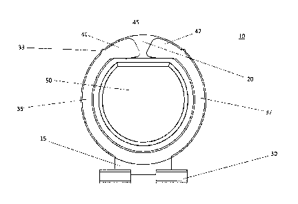
The present disclosure provides a valve for a respiratory bypass conduit, the valve further comprised of an inner frame that provides rigidity to a flexible outer seal. The inner frame has guiding flanges to guide the valve within he conduit, and a hinge portion to be secured within a slot of the conduit. Together, the hinge and the guiding flanged help the valve move from a first position to a second position. The present disclosure also provides for a method of assembling the valve for respiratory bypass conduit, whereby the inner frame is aligned with and inserted into the outer seal until a peripheral gap of the outer seal substantially houses the inner frame and an inner periphery of the inner frame surrounds a recessed portion of the outer seal to secure the outer seal in the correct orientation relative to the inner frame.
La présente divulgation concerne une vanne pour un conduit de dérivation respiratoire comprenant un cadre interne fournissant une rigidité à un joint détanchéité externe flexible. Le cadre interne dispose de rebords de guidage visant à guider la vanne au sein du conduit et une partie charnière devant être fixée à lintérieur dune fente du conduit. La charnière et le rebord de guidage permettent à la vanne de se déplacer entre une première position et une deuxième position. La présente divulgation concerne également un procédé dassemblage de la vanne pour un conduit de dérivation respiratoire, dans lequel le cadre interne est aligné avec le joint détanchéité et inséré dans ledit joint jusquà ce quun espace périphérique du joint détanchéité externe loge substantiellement le cadre interne et quune périphérie interne du cadre interne entoure une partie évidée du joint détanchéité externe, dans le but de le fixer dans lorientation adéquate par rapport au cadre interne.
Note: Claims are shown in the official language in which they were submitted.
Note: Descriptions are shown in the official language in which they were submitted.
2024-08-01:As part of the Next Generation Patents (NGP) transition, the Canadian Patents Database (CPD) now contains a more detailed Event History, which replicates the Event Log of our new back-office solution.
Please note that "Inactive:" events refers to events no longer in use in our new back-office solution.
For a clearer understanding of the status of the application/patent presented on this page, the site Disclaimer , as well as the definitions for Patent , Event History , Maintenance Fee and Payment History should be consulted.
| Description | Date |
|---|---|
| Letter Sent | 2024-06-25 |
| Grant by Issuance | 2024-06-25 |
| Inactive: Cover page published | 2024-06-24 |
| Pre-grant | 2024-05-14 |
| Inactive: Final fee received | 2024-05-14 |
| Inactive: Office letter | 2024-03-28 |
| Letter Sent | 2024-03-11 |
| Notice of Allowance is Issued | 2024-03-11 |
| Inactive: Approved for allowance (AFA) | 2024-03-07 |
| Inactive: Q2 passed | 2024-03-07 |
| Amendment Received - Response to Examiner's Requisition | 2023-11-15 |
| Amendment Received - Voluntary Amendment | 2023-11-15 |
| Inactive: Report - No QC | 2023-07-25 |
| Examiner's Report | 2023-07-25 |
| Letter Sent | 2023-07-14 |
| Advanced Examination Requested - PPH | 2023-06-27 |
| Request for Examination Requirements Determined Compliant | 2023-06-27 |
| All Requirements for Examination Determined Compliant | 2023-06-27 |
| Amendment Received - Voluntary Amendment | 2023-06-27 |
| Advanced Examination Determined Compliant - PPH | 2023-06-27 |
| Request for Examination Received | 2023-06-27 |
| Common Representative Appointed | 2020-11-07 |
| Inactive: Associate patent agent added | 2020-07-23 |
| Inactive: Office letter | 2020-07-23 |
| Inactive: Office letter | 2020-07-23 |
| Revocation of Agent Requirements Determined Compliant | 2020-07-23 |
| Appointment of Agent Requirements Determined Compliant | 2020-07-23 |
| Appointment of Agent Request | 2020-07-06 |
| Revocation of Agent Request | 2020-07-06 |
| Inactive: COVID 19 - Deadline extended | 2020-07-02 |
| Inactive: Cover page published | 2020-01-05 |
| Application Published (Open to Public Inspection) | 2020-01-05 |
| Common Representative Appointed | 2019-10-30 |
| Common Representative Appointed | 2019-10-30 |
| Inactive: IPC assigned | 2018-07-18 |
| Inactive: IPC assigned | 2018-07-13 |
| Inactive: IPC assigned | 2018-07-13 |
| Inactive: First IPC assigned | 2018-07-13 |
| Inactive: IPC assigned | 2018-07-13 |
| Inactive: IPC assigned | 2018-07-13 |
| Filing Requirements Determined Compliant | 2018-07-12 |
| Inactive: Filing certificate - No RFE (bilingual) | 2018-07-12 |
| Application Received - Regular National | 2018-07-06 |
| Small Entity Declaration Determined Compliant | 2018-07-05 |
There is no abandonment history.
The last payment was received on 2023-07-04
Note : If the full payment has not been received on or before the date indicated, a further fee may be required which may be one of the following
Please refer to the CIPO Patent Fees web page to see all current fee amounts.
| Fee Type | Anniversary Year | Due Date | Paid Date |
|---|---|---|---|
| Application fee - small | 2018-07-05 | ||
| MF (application, 2nd anniv.) - small | 02 | 2020-07-06 | 2020-07-03 |
| MF (application, 3rd anniv.) - small | 03 | 2021-07-05 | 2021-06-29 |
| MF (application, 4th anniv.) - small | 04 | 2022-07-05 | 2022-06-29 |
| Request for examination - small | 2023-07-05 | 2023-06-27 | |
| MF (application, 5th anniv.) - small | 05 | 2023-07-05 | 2023-07-04 |
| Final fee - small | 2024-05-14 | ||
| MF (patent, 6th anniv.) - small | 2024-07-05 | 2024-07-04 |
Note: Records showing the ownership history in alphabetical order.
| Current Owners on Record |
|---|
| SMART RS INC. |
| Past Owners on Record |
|---|
| FRANCESCO FIORENZA |

