Note: Descriptions are shown in the official language in which they were submitted.
05002993-2163CA
METHOD AND SYSTEM FOR DETECTING AN ABNORMAL ENGINE START
TECHNICAL FIELD
The present disclosure relates generally to gas turbine engines, and more
particularly to
detecting an abnormal engine start.
BACKGROUND OF THE ART
When an engine starts abnormally, this may lead to distress and/or damage to
the
engine. To address this issue, engine control systems sometimes measure the
temperature of an engine during the engine start using a temperature probe. In
the event
that the temperature of the engine exceeds a specific value, the engine is
shut down by
the engine control system.
However, the temperature probe may not be able to obtain an accurate
temperature
measurement until the engine is idling. As such, by the time a temperature
measurement
of the engine exceeds the specific value during an abnormal engine start, the
engine may
have already been distressed and/or damaged.
As such there is room for improvement.
SUMMARY
In one aspect, there is provided a method for detecting an abnormal engine
start of a gas
turbine engine. The method comprises monitoring an inter-turbine temperature
of the
engine during engine start; comparing the inter-turbine temperature to an
inter-turbine
temperature threshold which depends on at least one additional parameter; and
detecting
an abnormal engine start when the inter-turbine temperature exceeds the
threshold.
In another aspect, there is provided a system for detecting an abnormal engine
start of a
gas turbine engine. The system comprises a processing unit and a non-
transitory
computer-readable memory having stored thereon program instructions executable
by the
processing unit. The program instructions executable by the processing unit
are for
monitoring an inter-turbine temperature of the engine during engine start;
comparing the
inter-turbine temperature to an inter-turbine temperature threshold which
depends on at
least one additional parameter; and detecting an abnormal engine start when
the inter-
turbine temperature exceeds the threshold.
1
CA 3011470 2018-07-13
05002993-2163CA
BRIEF DESCRIPTION OF THE DRAWINGS
Reference is now made to the accompanying figures in which:
Figure 1 is a schematic of an example gas turbine engine;
Figure 2 is a flowchart illustrating an example method for detecting an
abnormal start of a
gas turbine engine in accordance with an embodiment;
Figure 3 is an example graphical representation of a threshold for detecting
an abnormal
engine start; and
Figure 4 is a block diagram of an example computing device for implementing
the method
of Figure 2.
It will be noted that throughout the appended drawings, like features are
identified by like
reference numerals.
DETAILED DESCRIPTION
Figure 1 illustrates a gas turbine engine 10 for which an abnormal engine
start may be
detected using the methods and systems described herein. Note that while
engine 10 is a
turbofan engine, the methods and systems for detecting an abnormal engine
start may be
applicable to turboprop, turboshaft, auxiliary power units (APU), and other
types of aircraft
engines.
Engine 10 generally comprises in serial flow communication a fan 12 through
which
ambient air is propelled, a compressor section 14 for pressurizing the air, a
combustor 16
in which the compressed air is mixed with fuel and ignited for generating an
annular
stream of hot combustion gases, and a turbine section 18 for extracting energy
from the
combustion gases. Axis 11 defines an axial direction of the engine 10.
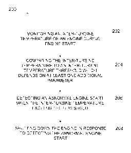
With reference to Figure 2, there is illustrated a flowchart of an example
method 200 for
detecting an abnormal engine start of a gas turbine engine, such as engine 10
of Figure
1. While the method 200 is described herein with reference to the engine 10 of
Figure 1,
this is for example purposes. The method 200 may be applied to other types of
engines
depending on practical implementations.
At step 202, an inter-turbine temperature of the engine is monitored during
engine start.
The inter-turbine temperature may be monitored by obtaining temperature
measurements
2
CA 3011470 2018-07-13
05002993-2163CA
from a temperature measurement device comprising one or more temperature
sensors.
With reference to Figure 1, in some embodiments, the one or more temperature
sensors
may be positioned between a low-pressure turbine 20 and a high-pressure
turbine 22 of
the turbine section 18. The location of the temperature sensors may vary
depending on
the practical implementation. The inter-turbine temperature may be dynamically
measured in real time, or may be recorded regularly in accordance with any
suitable time
interval. Step 202 may comprises triggering measurements of inter-turbine
temperature
whenever method 200 is initiated.
Referring back to Figure 2, at step 204, the inter-turbine temperature is
compared to an
inter-turbine temperature threshold which depends on at least one additional
parameter.
The at least one additional parameter may vary depending on practical
implementations.
In some embodiments, the at least one additional parameter comprises engine
rotational
speed. In some embodiments, the at least one additional parameter comprises
time.
At step 206, an abnormal engine start is detected when the inter-turbine
temperature
exceeds the threshold. In some embodiments, when the abnormal engine start is
detected, an indication of the abnormal engine start may be provided to the
pilot, crew
members and/or service crew.
In some embodiments, the method 200 comprises an optional step 208 of shutting
down
the engine 10 in response to detecting the abnormal engine start. For example,
if an
abnormal engine start is detected for a ground start, the engine 10 may
automatically be
shut down. Accordingly, the method 200 may be directed to a method for
shutting down a
gas turbine engine.
It should be appreciated that by having the inter-turbine temperature
threshold which
depends on at least one additional parameter, this reduces the risk of damage
to the
engine 10 which may have otherwise occurred if the inter-turbine temperature
threshold
was independent of additional parameters. The inter-turbine temperature
threshold which
depends On at least one additional parameter may be designed in a manner to
reduce the
risk of damage to the engine 10 compared to an independent temperature
threshold
In some embodiments, the inter-turbine temperature threshold depends on engine
rotational speed (Ng). With additional reference to Figure 3, an example inter-
turbine
temperature threshold 304 is illustrated that depends on the engine rotational
speed. The
inter-turbine temperature threshold 304 has a constant value 308 when the
engine
rotational speed of the engine 10 is within a first range 310 of engine
rotational speeds.
3
CA 3011470 2018-07-13
05002993-2163CA
The inter-turbine temperature threshold 304 has no value when the engine
rotational
speed of the engine 10 is within a second range 330 of engine rotational
speeds. As
such, in this example, the inter-turbine temperature threshold 304 has a limit
320 based
on engine rotational speed. The ranges 310 330 may be defined in terms of a
percentage of a maximum engine rotational speed of the engine 10. For example,
the first
range 310 may correspond to a range of 0% to N% and the second range 330 may
correspond to a range of N% to 100%. Alternatively, the ranges 310, 330 may be
defined
in terms of an actual engine rotational speed (e.g., in revolutions per
minute).
As shown in Figure 3, a curve 302 illustrates a measurement of inter-turbine
temperature
of the engine 10 as a function of the engine rotational speed. The engine
rotational speed
may be monitored by obtaining rotational speed measurements from a rotational
speed
measurement device comprising one or more sensors. The rotational speed
measurement device may comprise a tachometer, revolution-counter, and/or any
other
suitable device. Alternatively, the engine rotational speed is provided by an
engine
computer or an aircraft computer.
In this example, during the engine start, the inter-turbine temperature 3C2 is
compared to
the inter-turbine temperature threshold 304. As shown, the inter-turbine
temperature 302
increases until a point 306 where it exceeds the inter-turbine temperature
threshold 304.
Accordingly, an abnormal engine start is detected when the inter-turbine
temperature 302
exceeds the inter-turbine temperature threshold 304. In this example, the
engine 10 is
shut down in response to detecting the abnormal engine start and the curve 302
no
longer illustrates the inter-turbine temperature after the engine 10 has been
shut down.
In some embodiments, comparing the inter-turbine temperature 302 to the inter-
turbine
temperature threshold 304 comprises comparing the inter-turbine temperature
302 to the
constant value 308 when the engine rotational speed of the engine is within
the first range
310 of engine rotational speeds. For example, the engine rotational speed may
be
compared to an engine rotational speed threshold 322 for determining if the
inter-turbine
temperature 302 should be compared to the inter-turbine temperature threshold
304.
Accordingly, while the engine rotational speed is below the engine rotational
speed
threshold 322, the inter-turbine temperature 302 may be compared to the inter-
turbine
temperature threshold 304. In this example, the engine rotational speed
threshold 322 is
defined by an endpoint 316 of the first range 310 of engine rotational speeds.
4
CA 3011470 2018-07-13
05002993-21630A
In some embodiments, the endpoint 316 of the first range 310 of engine
rotational speeds
is based on a first offset 312 from at least one operating characteristic of
the engine 10. In
some embodiments, the operating characteristic is an expected light-off engine
rotational
speed 314 of the engine 10. By way of a specific and non-limiting example, the
expected
light-off engine rotational speed 314 of the engine 10 is approximately 20% of
the
maximum engine rotational speed. By way of another specific and non-limiting
example,
the expected light-off engine rotational speed 314 of the engine 10 is in the
range to 15 to
25% of the maximum engine rotational speed. Other values are contemplated,
depending
on implementation of the engine 10.
In some embodiments, the operating characteristic is an expected engine
rotational
speed where fuel is introduced into the engine 10. By way of a specific and
non-limiting
example, the engine rotational speed where fuel is introduced into the engine
10 is
approximately 15% of the maximum engine rotational speed. By way of another
specific
and non-limiting example, the engine rotational speed where fuel is introduced
into the
engine 10 is in the range to 10 to 20% of the maximum engine rotational speed.
Other
values are contemplated, depending on implementation of the engine 10.
The inter-turbine temperature threshold 304 may be based on the expected light-
off
engine rotational speed 314 of the engine 10 and/or the expected engine
rotational speed
where fuel is introduced into the engine 10. For example, the engine
rotational speed
corresponding to the limit 320 of the inter-turbine temperature threshold 304
may be set
based on the expected light-off engine rotational speed 314 of the engine 10
and/or the
expected engine rotational speed where fuel is introduced into the engine 10.
In some embodiments, the inter-turbine temperature threshold 304 is determined
based
on a temperature profile 324 of the engine 10 as a function of engine
rotational speed for
acceptable engine starts. Acceptable engine starts may be determined as a
function of
various parameters, such as a range of aircraft altitudes and a range of
ambient
temperatures. The temperature profile 324 may be obtained by measuring and
recording
the temperature of the engine 10 as a function of engine rotational speed,
during engine
start, over a range of altitudes and a range of ambient temperatures. For
example, the
temperature of the engine 10 may be measured during engine start at a low
altitude (e.g.,
below 1000 meters) and measured at a high altitude (e.g., above 2,400 meters).
Similarly,
the temperature of the engine 10 may be measured during engine start at a cola
ambient
temperature (e.g., below -30 degrees Celsius) and measured at a warm ambient
temperature (e.g., above 25 degrees Celsius). Measurements at a combination of
CA 3011470 2018-07-13
05002993-21630A
different altitudes and ambient temperatures may be done. The temperature
profile 324
may be determined by setting a lower limit 332 and an upper limit 334 of the
temperature
profile 324. The lower limit 332 and the upper limit 334 may be set such that
the
temperature measurements of the engine 10 for the ranges of altitudes and
ambient
temperatures are between the lower limit 332 and the upper limit 334.
Alternately, or in
addition, the temperature profile 324 may be obtained by computer simulation
that
simulates the temperature of the engine 10 during start over a range of
altitudes and
ambient temperatures.
In some embodiments, the constant value 308 of the inter-turbine temperature
threshold
304 is based on a second offset 318 from an acceptable temperature of the
engine 10
prior to light-off. As illustrated, the acceptable temperature of the engine
10 prior to light-
off may be obtained from the temperature profile 324. For example, the second
offset 318
may be from the upper limit 334 of the temperature profile 324. Alternatively,
the second
offset 318 may be based on the lower limit 332 of the temperature profile 324,
or the
second offset 318 may be based on an average of the upper limit 334 and lower
limit 332.
By way of a specific and non-limiting example, the second offset 318 is set to
approximately 250 degrees Celsius. By way of another specific and non-limiting
example,
the second offset 318 is set somewhere in the range of 100 degrees Celsius and
300
degrees Celsius. Other values for the second offset 318 are contemplated.
In some embodiments, the inter-turbine temperature threshold 304 is determined
from the
temperature profile 324 based on at least one of a frequency of occurrence of
an
abnormal engine start, tolerance of components of the engine 10 and at least
one of the
offsets 312, 318.
The frequency of occurrence of an abnormal engine start refers to a
probability of the
engine 10 having an abnormal engine start. The frequency of occurrence of an
abnormal
engine start may be determined from measuring engine starts and/or computer
simulation. For example, if the frequency of occurrence of an abnormal engine
start is
less than 0.1%, a larger offset for the second offset 318 from the temperature
profile 324
may be used compared to when a frequency of occurrence is greater than 0.1%.
By way
of another example, if the engine 10 has a frequency of occurrence less than
1%, a larger
offset for the second offset 318 from the temperature profile 324 may be used
compared
to when a frequency of occurrence is greater than 1%. Other values are
contemplated,
depending on implementation of the engine 10.
6
CA 3011470 2018-07-13
05002993-2163CA
Tolerance of components of the engine 10 refers to a permissible limit of one
or more
components of the engine 10 prior to distress, damage and/or failure. The
tolerance of
components may be known based on the components used to build the engine 10 or
may
be determined from measurements and/or computer simulations. For example, if
it is
known that a certain component of the engine 10 may be damaged at 650 degrees
Celsius and that prior to light-off an acceptable engine start would likely
not exceed 200
degrees Celsius, then the second offset 318 may be set to 250 degrees Celsius.
By way
of another example, if it is known that a certain component of the engine 10
may be
damaged at 700 degrees Celsius and that prior to light-off an acceptable
engine start
would likely not exceed 220 degrees Celsius, then the second offset 318 may be
set to
300 degrees Celsius. Other values are contemplated, depending on
implementation of
the engine 10.
While the inter-turbine temperature threshold 304 is illustrated as a constant
value 308 in
the first range 310 of engine rotational speeds, in other embodiments the
inter-turbine
temperature threshold 304 may vary in value over tne first range 310 of engine
rotational
speeds.
In some embodiments, the inter-turbine temperature threshold depends on a time
parameter. The inter-turbine temperature threshold may comprise one or more
temperature values, each having a corresponding duration associated thereto.
As such,
in this example, the inter-turbine temperature threshold is exceeded if the
inter-turbine
temperature of the engine 10 exceeds a specific one of the one or more
temperate values
for the corresponding duration of that specific temperature value.
With reference to Table 1, an example inter-turbine temperature threshold is
shown
associated with corresponding durations. As shown, the inter-turbine
temperature
threshold is deemed exceeded when the inter-turbine temperature is measured at
500
degrees Celsius or greater for at least 30 seconds. The inter-turbine
temperature
threshold is deemed exceed when the inter-turbine temperature is measured at
600
degrees Celsius or greater for at least 15 seconds.
Temperature Duration
500 degrees Celsius 30 seconds
600 degrees Celsius 15 seconds
Table 1: Inter-turbine temperature threshold based on time
7
CA 3011470 2018-07-13
05002993-21630A
Accordingly, the inter-turbine temperature threshold may have a first minimum
temperature value for a first minimum duration and a second minimum
temperature value
for a second minimum duration, where the first and second minimum temperature
values
are different from each other. The first minimum temperature value is exceeded
when the
inter-turbine temperature is measured at or above the first minimum
temperature for at
least the first minimum duration. Similarly, the second minimum temperature
value is
exceeded when the inter-turbine temperature is measured at or above the second
minimum temperature for at least the second minimum duration. The first and
second
minimum durations may be different from each other. In some embodiments, the
first
minimum temperature value is lower than the second minimum temperature value
and
the first minimum duration is longer than the second minimum duration. The
number of
minimum temperature values may vary depending on practical implementations.
For
example, a single minimum temperature value having a single minimum duration
may be
used. In other cases, more than two minimum temperature values each having a
respective minimum duration may be used.
The inter-turbine temperature threshold may comprise one or more temperature
ranges,
each having a corresponding duration associated thereto. As such, in this
example, the
inter-turbine temperature threshold is exceeded if the inter-turbine
temperature of the
engine 10 is within a specific one of the one or more temperate ranges for the
corresponding duration of that specific temperature range.
With reference to Table 2, another example inter-turbine temperature threshold
is shown
associated with corresponding durations. As shown, the inter-turbine
temperature
threshold is deemed exceeded when the inter-turbine temperature is measured
within a
range of 500 to 600 degrees Celsius for at least 20 seconds. The inter-turbine
temperature threshold is deemed exceed when the inter-turbine temperature is
measured
within a range of 600 to 700 degrees Celsius for at least 15 seconds. The
inter-turbine
temperature threshold is deemed exceed when the inter-turbine temperature is
measured
within a range of 700 to 800 degrees Celsius for at least 10 seconds.
Temperature Duration
500 to 600 degrees Celsius 20 seconds
600 to 700 degrees Celsius 15 seconds
700 to 800 degrees Celsius 10 seconds
Table 2: Inter-turbine temperature threshold based on time
8
CA 3011470 2018-07-13
05002993-2163CA
The number of temperature ranges and the corresponding duration may vary
depending
on practical implementation. For example, the number of temperature ranges may
be less
than three (e.g., one or two) or more than three The values for the
temperature ranges
may also vary depending on practical implementation.
Accordingly, comparing the inter-turbine temperature to the inter-turbine
temperature
threshold at 204 may comprise comparing the inter-turbine temperature to the
inter-
turbine temperature threshold for a period of time. For example, the inter-
turbine
temperature may be monitored and when the inter-turbine temperature exceeds a
temperature value or is within a temperature range, a time counter may be
started. When
the time counter exceeds a corresponding duration associated with the
temperature value
being exceeded or the temperature range that the inter-turbine temperature is
currently
in, then it may be determined that the inter-turbine temperature threshold has
been
exceeded. The time counter may be reset when the inter-turbine temperature
falls below
the temperature value or falls outside of the temperature range.
In some embodiments, detecting an abnormal start of the engine 10 comprises
detecting
an abnormal engine start when the inter-turbine temperature exceeds a
temperature
value of the inter-turbine temperature threshold for a duration. For example,
if the inter-
turbine temperature is above 500 degrees Celsius for at least 30 seconds, an
abnormal
engine start may be detected. By way of another example, if the inter-turbine
temperature
is above 600 degrees Celsius for at least 15 seconds, an abnormal engine start
may be
detected.
In some embodiments, detecting an abnormal start of the engine 10 comprises
detecting
an abnormal engine start when the inter-turbine temperature is within a
temperature
range of the inter-turbine temperature threshold for a duration. For example,
if the inter-
turbine temperature is within 500 to 600 degrees Celsius for at least 20
seconds, an
abnormal engine start may be detected. By way of another example, if the inter-
turbine
temperature is within 600 to 700 degrees Celsius for at least 15 seconds, an
abnormal
engine start may be detected.
The methcd 200 may be implemented by a control system. With reference to
Figure 4,
the control system may be implemented by a computing device 410, comprising a
processing unit 412 and a memory 414 which has stored therein computer-
executable
instructions 416. The processing unit 412 may comprise any suitable devices
configured
to implement the method 200 such that instructions 416, when executed by the
9
CA 3011470 2018-07-13
05002993-2163CA
computing device 410 or other programmable apparatus, may cause the
functions/acts/steps performed as part of the method 200 as described herein
to be
executed. The processing unit 412 may comprise, for example, any type of
general-
purpose microprocessor or microcontroller, a digital signal processing (DSP)
processor, a
central processing unit (CPU), an integrated circuit, a field programmable
gate array
(FPGA), a reconfigurable processor, other suitably programmed or programmable
logic
circuits, or any combination thereof.
The memory 414 may comprise any suitable known or other machine-readable
storage
medium. The memory 414 may comprise non-transitory computer readable storage
medium, for example, but not limited to, an electronic, magnetic, optical,
electromagnetic,
infrared, or semiconductor system, apparatus, or device, or any suitable
combination of
the foregoing. The memory 414 may include a suitable combination of any type
of
computer memory that is located either internally or externally to device, for
example
random-access memory (RAM), read-only memory (ROM), compact disc read-only
memory (CDROM), electro-optical memory, magneto-optical memory, erasable
programmable read-only memory (EPROM), and electrically-erasable programmable
read-only memory (EEPROM), Ferroelectric RAM (FRAM) or the like. Memory 414
may
comprise any storage means (e.g., devices) suitable for retrievably storing
machine-
readable instructions 416 executable by processing unit 412. Note that the
control system
can be implemented as part of a full-authority digital engine controls (FADEC)
or other
similar device, including electronic engine control (EEC), engine control unit
(ELIO), and
the like.
The methods and systems for detecting an abnormal engine start of an engine
described
herein may be implemented in a high level procedural or object oriented
programming or
scripting language, or a combination thereof, to communicate with or assist in
the
operation of a computer system, for example the computing device 410.
Alternatively, the
methods and systems detecting an abnormal engine start of an engine may be
implemented in assembly or machine language. The language may be a compiled or
interpreted language. Program code for implementing the methods and systems
for
detecting an abnormal engine start of an engine may be stored on a storage
media or a
device, for example a ROM, a magnetic disk, an optical disc, a flash drive, or
any other
suitable storage media or device. The program code may be readable by a
general or
special-purpose programmable computer for configuring and operating the
computer
when the storage media or device is read by the computer to perform the
procedures
described herein. Embodiments of the methods and systems for detecting an
abnormal
CA 3011470 2018-07-13
05002993-21630A
engine start of an engine may also be considered to be implemented by way of a
non-
transitory computer-readable storage medium having a computer program stored
thereon. The computer program may comprise computer-readable instructions
which
cause a computer, or more specifically the processing unit 412 of the
computing device
410, to operate in a specific and predefined manner to perform the functions
described
herein, for example those described in the method 200.
Computer-executable instructions may be in many forms, including program
modules,
executed by one or more computers or other devices. Generally, program modules
include routines, programs, objects, components, data structures, etc., that
perform
particular tasks or implement particular abstract data types. Typically the
functionality of
the program modules may be combined or distributed as desired in various
embodiments.
The above description is meant to be exemplary only, and one skilled in the
art will
recognize that changes may be made to the embodiments described without
departing
from the scope of the invention disclosed. Still other modifications which
fall within the
scope of the present invention will be apparent to those skilled in the art,
in Jight of a
review of this disclosure.
Various aspects of the methods and systems for detecting an abnormal engine
start of an
engine may be used alone, in combination, or in a variety of arrangements not
specifically
discussed in the embodiments described in the foregoing and is therefore not
limited in its
application to the details and arrangement of components set forth in the
foregoing
description or illustrated in the drawings. For example, aspects described in
one
embodiment may be combined in any manner with aspects described in other
embodiments. Although particular embodiments have been shown and described, it
will
be obvious to those skilled in the art that changes and modifications may be
made
without departing from this invention in its broader aspects. The scope of the
following
claims should not be limited by the embodiments set forth in the examples, but
should be
given the broadest reasonable interpretation consistent with the description
as a whole.
11
CA 3011470 2018-07-13