Note: Descriptions are shown in the official language in which they were submitted.
CA 03012043 2018-07-19
WO 2017/127290 PCT/US2017/013295
TEMPERATURE REGULATING GARMENT
RELATED APPLICATIONS
This application is a continuation-in-part of, and claims priority to
U.S. patent application Ser. No. 14/513,429 filed October 14, 2014, which is a
continuation-in-part of, and claims priority to U.S. patent application Ser.
No.
14/490,106 filed September 18, 2014, which is a continuation-in-part of and
claims
priority to U.S. patent application Ser. No. 14/324,707 filed July 7, 2014.
BACKGROUND
This invention relates generally to clothing, and more specifically to
garments of the type worn by medical personnel in operating rooms, and other
applications.
To create a proper working environment, medical operating rooms
are usually maintained at a certain temperature which is often relatively cold
to
offset hot lighting, to keep stressed doctors and nurses comfortable while
working,
and/or to inhibit the spread of bacteria. In most hospitals, medical personnel
are
forbidden from bringing street clothing into the operating room. In some
cases,
anesthesiologists, nurses and any other personnel in the operating room who
are
not scrubbed in may wear a medical or hospital issue warm up jacket over their
scrubs; however, these garments do not keep the wearer at a comfortable
temperature. Excessive layers of garments are also counterproductive in the
operating room, since they may restrict the mobility or dexterity of the
personnel.
On the other hand, limbs and fingers tend to get stiff when the body is cold.
Anesthesiologists, nurse anesthetists, perioperative nurses, and others
participating in the operating room need their body to be at a comfortable
level of
temperature and dexterity to perform their functions over many hours.
Additionally, medical personnel suffering from hormonal changes often have
abnormal body temperature perceptions while participating in surgery. One
example is post menopausal women, who suffer from periodic drastic perceived
changes in body temperature and often feel much warmer than other individuals
in
the same room. Also, the surgical treatment of burn patients or pediatric
patients
1
CA 03012043 2018-07-19
WO 2017/127290 PCT/US2017/013295
usually requires the operating or treating room to be warmer than average for
the
patient's benefit. These situations have created a need for alternative
measures for
keeping medical personnel, or other users comfortable.
SUMMARY
The above-listed needs are met or exceeded by the present
temperature regulating garment, usable in many situations when a wearer
desires
enhanced temperature regulation, and in particular for keeping operating room
personnel at a desired temperature. A specially designed warm up jacket or
vest is
provided to be worn over scrubs. A version of the present garment is a
specially
designed vest provided to be worn over scrubs and under any sort of warm up
jacket or surgical gown. In a preferred embodiment, the garment is made of a
thermally insulating material, such as GORE surgical fabric, preferably level
3 or
4. Furthermore, the present garment features at least one and preferably
several
pockets which are designed to releasably accommodate a temperature element
such as a reusable heatable gel pack or chemical warming pack, cooling pack or
the like.
It is contemplated that the size and locations of the temperature
regulating elements are variable to suit the situation. The temperature
regulating
element can be a heating element, such as a battery-powered heating element,
chemical warming pack, reusable heated gel pack or warmed up bag of IV fluid,
or
a cooling element, such as a phase change cooling element, chemical cooling
pack,
reusable cooled gel pack, refrigerated bag of IV fluid or ice packs. While
preferably made of mesh material, the pockets are designed to allow the heat
generated by the regulating elements to be distributed generally uniformly
throughout an inside chamber defined by the present garment. The garment also
features at least one single layer or double layer pocket, designed to hold a
heating
or cooling pack over the wearer's lumbar region. When provided as a vest, the
present garment can be reversed to provide an additional layer of non-
fenestrated
material between the wearer and the temperature element. Such an additional
2
CA 03012043 2018-07-19
WO 2017/127290 PCT/US2017/013295
layer is helpful when a cooling element is used to prevent the discomfort of
localized cold upon the skin.
There also exists a need to easily launder garments with temperature
regulating elements. After placing the elements into the pockets, the user has
to
remove each element before placing the garment into the laundry machine. This
need is met by the present temperature regulating garment, which features an
inner
liner panel which has pockets for the temperature regulating elements.
Therefore,
it is contemplated that the inner liner panel is preferably removable, and the
user
removes the liner panel and launders the garment. After laundering, the liner
panel
is reattached to the garment.
More specifically, a garment for regulating temperature is provided,
with a body including a back panel and at least one front panel and at least
partially joined along at least one common edge, an inner liner panel fastened
to an
inner surface of at least one of the back panel and to the at least one front
panel
with an first surface, and a second surface opposite to the first surface of
the inner
liner panel, and at least one pocket with top, bottom and side edges, being
fastened
to at least one of the first and second surfaces of the inner liner panel. The
at least
one pocket has at least one side opening.
In another embodiment, a panel is provided for use with a garment for
regulating temperature having a body including a back panel, at least one
front
panel, and is at least partially joined along at least one common edge, the
joined
panels defining an inside chamber. The panel has a web with a first surface, a
second surface, right and left side edges, and at least one attachment
disposed on
the surface of the web of the panel. At least one pocket is provided having
top,
bottom, and side edges, and is fastened to the surface of the web of the panel
on at
least one said side edge of the at least one pocket. The at least one pocket
has at
least one side opening.
In still another embodiment, a garment is provided for regulating
temperature, including a panel having a first surface and a second surface,
and
right and left side edges; at least one attachment disposed on at least one of
the
3
CA 03012043 2018-07-19
WO 2017/127290 PCT/US2017/013295
first and second surfaces of the section of the panel; and at least one pocket
being
fastened to at least one of the first and second surfaces of the panel.
BRIEF DESCRIPTION OF THE DRAWINGS
FIG. 1 is a front view of the present temperature regulating garment
shown in an open position with a temperature regulating element exploded out;
FIG. 2 is front view of the garment of FIG. 1 shown without the
temperature regulating element;
FIG. 3a is a cross-section taken along the line 3a-3a of FIG. 2 and in
the direction generally indicated;
FIG. 3b is a cross-section taken along the line 3b-3b of FIG. 2 and in
the direction generally indicated;
FIG. 3c is a cross-section taken along the line 3c-3c of FIG. 1 and in
the direction generally indicated;
FIG. 4 is a front view of the present garment;
FIG. 5 is a front view of an alternate embodiment of the garment of
FIG. 4;
FIG. 6 is a front view of another alternate embodiment of the
garment of FIG. 4;
FIG. 7 is a front view of another alternate embodiment shown in an
open position with a temperature regulating element exploded out;
FIG. 8 is a front view of another alternate embodiment shown in an
open position;
FIG. 9 is a front view of the garment of FIG. 8 shown in an open
position with an inner liner panel exploded out;
FIG. 10 is a front view of another alternate embodiment shown in an
open position with an inner liner panel exploded out;
FIG. 11 is a front view of another alternate embodiment of the
garment of FIG. 10 shown in an open position with an inner liner panel
exploded
out;
4
CA 03012043 2018-07-19
WO 2017/127290 PCT/US2017/013295
FIG. 12 is a front view of another alternate embodiment shown in an
open position with an inner liner panel exploded out;
FIG. 13A ¨ 13D are front views of alternate embodiments of the
inner liner panel of FIG. 12;
FIG. 14 is a front view of another alternate embodiment of the
garment of FIG. 12 shown in an open position with an inner liner panel
exploded
out;
FIG. 15 is a front view of another alternate embodiment shown in an
open position;
FIG. 16A ¨ 16C are front views of alternate embodiments of an inner
liner panel of FIG. 15;
FIG. 17 is a front view of an alternate embodiment of an inner liner
panel of FIG. 15;
FIG. 17a is a cross-section taken along the line 17a-17a of FIG. 17
and in the direction generally indicated;
FIG. 18 is a front view of an alternate embodiment of a garment
shown in FIGs. 12-14; FIG. 19 is an alternate view of the embodiment shown in
FIG. 18;
FIG. 20 is a front view of another alternate embodiment of the
present temperature regulating garment;
FIG. 21 is a cross-section taken along the lines 21-21 of FIG. 20 and
in the direction indicated generally; and
FIG. 22 is a schematic view of a person wearing the garment of
FIGs. 20 and 21.
DETAILED DESCRIPTION
Referring to FIGs. 1-2 and 4, a garment for regulating temperature is
generally designated 10, and in the preferred embodiment is a jacket including
a
body 12 with a back panel 14, at least one of a first front panel 16 and a
second
front panel 18. The first front panel 16 is partially joined along at least
one first
common edge 20 shared with the back panel 14. Likewise, the second front panel
5
CA 03012043 2018-07-19
WO 2017/127290 PCT/US2017/013295
18 is partially joined along at least one second common edge 22 shared with
the
back panel 14. As is known in the art, the common edges 20, 22 form seams. The
first front panel 16 and the second front panel 18 are joinable along
respective free
edges 24, 26, preferably by fasteners 28, such as snaps, buttons, clips,
zippers,
VELCRO hook and loop fastener material, and the like. Upon assembly, the
joined panels 14, 16 and 18 combine to define an inside chamber 29.
A first arm hole 30 is defined in part by an end 32 of a seam 34
formed by joining the common edges 20 of the first front panel 16 and the back
panel 14, and at an end 36 of the arm hole opposite the end 32 by a shoulder
seam
38 formed by a junction of the first front panel 16 and the back panel 14.
Likewise, a second arm hole 40 is defined by an end 42 of a second seam 44
formed by joining the common edges 22 of the second front panel 18 and the
back
panel 14, and at an end 46 of the arm hole 40 opposite the end 42 by a
shoulder
seam 48 formed by a junction of the second front panel 18 and the back panel
14.
A first sleeve 50 and a second sleeve 52 are optionally affixed
respectively to the first and second arm holes 30, 40. Preferably, the body
12, and
if provided, the sleeves, 50, 52 of the garment 10 are made of GORE surgical
fabric, level 3 or 4, but alternate embodiments are contemplated where the
body is
made of at least one layer of any thermally insulating, synthetic, non-linting
medically acceptable textile, including, but not limited to polyester fabric,
cotton
polyester fabric, surgical fabric, nylon or the like.
Referring now to FIG. 1, the garment 10 is depicted in an open
position such that an inner surface 54 of the back panel 14, an inner surface
56 of
the first front panel 16, and an inner surface 58 of the second front panel 18
are
shown. A first pocket 60 dimensioned for accommodating a temperature
regulating element 62 is fastened to the inner or interior surface 56 of the
first front
panel 16 approximately 10-15 centimeters from a bottom edge or hem 64 of the
first front panel to a bottom edge 65 of the pocket and approximately 4
centimeters
from a side edge 66 of the first front panel 16 to an adjacent pocket edge 67.
A
third pocket 68, preferably smaller than the first pocket 60, is fastened to
an outer
or exterior surface 70 of the first pocket 60. As an alternative, the third
pocket 68,
6
CA 03012043 2018-07-19
WO 2017/127290 PCT/US2017/013295
is directly fastened to the inner surface 56 of the first front panel 16, and
therefore
lies inside the first pocket 60.
Likewise, a second pocket 72 dimensioned for accommodating the
temperature regulating element 62 is fastened to an inner surface 58 of the
second
front panel 18 approximately 10-15 centimeters from a bottom edge or hem 76 of
the second front panel 18 to a bottom pocket edge 77 and approximately 4
centimeters from a side edge 78 of the second front panel 18 to an adjacent
pocket
edge 79. A fourth pocket 80, preferably smaller than the second pocket 72, is
fastened to an outer or exterior surface 82 of the second pocket 72. As an
alternative, a fourth pocket 80, is directly fastened to the inner surface 58
of the
second front panel 18, and therefore lies inside the second pocket 72.
The preferred dimension of the first and the second pockets 60, 72 is
25 cm deep or tall, and 20 cm wide. These pockets 60, 72 are sized to
accommodate a larger temperature regulating element 62, including but not
limited
to IV fluid bags, but may also hold a smaller temperature regulating element
such
as a chemical warming pack. The preferred dimensions of the third and fourth
pockets 68, 80 are 12 cm deep or tall and 16 cm wide. The bottom edge 65 of
the
first pocket 60 and the bottom edge 77 of the second pocket 72 are preferably
located 13 cm from bottom edges 88, 89 of the third and fourth pockets 68, 80,
respectively. These pockets 68, 80 are sized to accommodate a smaller
temperature regulating element 62, such as a chemical warming pack. For the
purposes of this application, the above-identified combinations of the first
and
third pockets 60 and 68, and the second and fourth pockets 72 and 80 will also
be
referred to as double pockets.
Referring now to FIG. 2, a fifth pocket 90 and a sixth pocket 92 for
accommodating a temperature regulating element 62 are fastened to the inner
surface 54 of the back panel 14 approximately 20-25 cm from a bottom edge 94
of
the back panel to a bottom edge 95 of the pockets. Advantageously, the fifth
and
sixth pockets 90, 92 are placed over a wearer's lumbar region to direct the
temperature regulating element 62 over this body region. Accordingly, the
preferred dimension of each of the fifth and sixth pockets 90, 92 is 12-25 cm
deep
7
CA 03012043 2018-07-19
WO 2017/127290 PCT/US2017/013295
or tall and 16-20 cm wide. In the preferred embodiment, as seen in FIG. 2, the
pockets 90 and 92 are separated by a seam 96. In FIG. 1, the seam 96 is
omitted,
leaving only a single pocket 90.
It is contemplated that at least one of the pockets 60, 68, 72, 80, 90
and 92 may have one of the temperature regulating elements 62 disposed inside
of
them at any given time. The location, dimensions, and design of the pockets
60,
68, 72, 80, 90 and 92 may vary from the above description to suit the
application,
provided that the pockets are constructed and arranged for allowing the heat
or
cooling from the temperature regulating element 62 to escape into the interior
chamber 29 and this chamber is thus maintained at a desired temperature and is
insulated from ambient temperature in the room, usually an operating room.
Thus,
the user will employ the type of temperature regulating element(s) 62 as
needed to
achieve a desired temperature within the interior chamber that has a perceived
differential from the ambient temperature of the room. It is to be understood
that
this desired temperature varies with the individual and the circumstances of
the
application.
The garment 10 is preferably made of a non-linting, temperature
insulating textile which can withstand multiple industrial or hospital
launderings.
Advantageously, the preferred material maintains the temperature within the
inside
chamber 29. In the preferred embodiment, the pockets 60, 72, 68, 80, 90, and
92
of the garment 10 are made of polyester fabric, preferably mesh which allows
for
enhanced conductivity of the desired temperature in the inside chamber 29.
However, in other embodiments, the pockets 60, 72, 68, 80, 90, 92, can be made
of
other textiles. The pockets 60, 72, 68, 80, 90, 92, are fastened to the
garment 10 to
withstand the weight of a one liter bag of IV fluid as well as repeated use of
the
pockets. In the preferred embodiment, the pockets 60, 72, 68, 80, 90, 92, are
sewn
to the inner or interior surfaces 56, 58, 54, respectively, of the front first
panel 16,
the second front panel 18, and the back panel 14, although alternate ways of
fastening the pockets to the front first panel, the second front panel, and
the back
panel are envisioned.
8
CA 03012043 2018-07-19
WO 2017/127290 PCT/US2017/013295
In the preferred embodiment, the temperature regulating element 62
is a heating element, such as a battery powered heating element, a chemical
warming pack, warmed up bag of IV fluid or other elements that are remotely
heated and placed into the pockets 60, 72, 68, 80, 90, 92, while warm.
Advantageously, including a heating element allows the user to remain at a
comfortable temperature while working in a cold operating room. In other
embodiments, similar benefits are obtained when the temperature regulating
element 62 is a cooling element, including elements that are remotely cooled,
chemical cooling packs, refrigerated bags of IV fluid or ice packs. The
placement
of, and amounts of the temperature regulating element 62 can be individualized
to
the needs of the wearer. One skilled in the art will appreciate that the
temperature
regulating element 62 is not limited to those listed and can be substituted
with
similar temperature regulating elements.
Referring now to FIGs. 3a, 3c and 4, at least one supplemental
pocket 102 is fastened to an outer or exterior surface 104 of either or both
of the
first and second front panels 16, 18. As is known in the art, such
supplemental
pockets 102 can be used to hold a pen, pencil or other instrument needed by
the
wearer.
Referring now to FIGs. 1, 2, and 4 the garment 10 preferably has a
neck 108, formed by a top edge 110 of the first front panel 16, a top edge 112
of
the back panel 14, and a top edge 114 of the second front panel 18. In the
preferred embodiment, a collar 116, which will keep the wearer's neck warm, is
affixed to the neck 108 of the garment 10. The garment 10 also preferably
includes a cuff 118 affixed to each of the sleeves 50, 52. Note that the
collar 116
is optional (FIG. 5). Advantageously, the cuffs 118 will keep the wrists of
the
wearer warm, and will serve to prevent heat from escaping into the room. The
collar 116 and the cuffs 118 are preferably made of rib knit polyester,
however
other materials are contemplated.
Referring now to FIG. 6, an alternate embodiment of the garment is
shown, generally designated 120. Components shared with the garment 10 are
designated with identical reference numbers. The main distinction of the
garment
9
CA 03012043 2018-07-19
WO 2017/127290 PCT/US2017/013295
120 is it does not have the first and second sleeves 50, 52. This embodiment
is
advantageous in that it helps keep the wearer's core warm or cool while being
worn under a conventional warm up jacket or surgical gown. The garment 120
shown in FIG. 6 is preferably reversible such that the respective inner
surfaces 56,
58, of the first 16 and second 18 front panels become an outer or exterior
surface
of the first 16 and second 18 front panels, respectively, and the inner
surface 54 of
the back panel 14 becomes an outer or exterior surface of the back panel 14.
Reversing the garment 120 will place a non-fenestrated layer of material, that
being the material of the body 12, between the wearer's skin and the
temperature
regulating element 62, particularly important if 62 is a cooling element. A
temperature regulating element 62 for maintaining temperature range within the
chamber between the vest and a conventional warm up jacket or between the vest
and a surgical gown can be disposed into one or more pockets 60, 72, 68, 80,
90,
and 92.
Furthermore, the garments 10 and 120 are designed to meet
guidelines for garments worn in hospital operating rooms as set forth by the
American Association of PeriOperative Registered Nurses (AORN).
Referring now to FIG. 7, an alternate embodiment of the garment is
shown, generally designated 130. Components shared with the garment 10 are
designated with identical reference numbers. The main distinction of the
garment
130, compared to the garments described above, is that the attachments of at
least
one of the pockets 60, 72, 90 to the back, first front, and second front
panels 14,
16, 18, or the attachments of at least one of the pockets 68 and 80 to the
pockets 60
and 72 have openings to facilitate the placement of at least one temperature
regulating element connected by at least one wire and for the attached wires
to
have a neat appearance and to reduce tangling of the wires. Ultimately, the
wires
are connected to a battery pack for generating the desired heating or cooling.
In a preferred embodiment, openings 132 are preferably centered on
edges 134 and 67 of the first pocket 60 facing the fifth pocket 90. In the
preferred
embodiment, each opening 132 is between 2-2.5 inches long. Similar openings
136 are preferably provided on edges 138 and 79 of the second pocket 72 facing
CA 03012043 2018-07-19
WO 2017/127290 PCT/US2017/013295
the fifth pocket 90. The fifth pocket 90 has openings 140 and 142 preferably
centered on edges 144 and 146. The openings 140 and 142 are also preferably 2-
2.5 inches long. Preferably, the size of the openings 132, 136, 140, and 142
are
smaller than a shortest size of the temperature regulating element 62 to
prevent the
temperature regulating element from falling through the openings regardless of
its
direction in the pockets. It is contemplated that the size and location of the
openings 132, 136, 140, and 142 may vary to suit the application.
Preferably, there additionally are strap-like attachments 148, 150
with at least one end removably attached to the inner surfaces 54, 56, 58. In
the
preferred embodiment, the attachments 148, 150 are attached to the inner
surface
54 of the back panel 14. These removable attachments 148, 150 keep a
connecting
wire 152 connecting the respective heating elements 62 from hanging freely.
The
removable attachments 148, 150 are fastened to the inner surface 54 of the
back
panel 14 with fasteners 151 located at at least one of the top and bottom of
each of
the removable attachments 148, 150. In the preferred embodiment, the removable
attachments 148, 150 are detachable with a fastener 151 at one end, and
permanently attached on the end opposite to the end with the fastener 151.
These
fasteners include, but are not limited to, VELCRO hook-and-loop fasteners,
snaps, or buttons.
The removable attachments 148, 150, when fastened to the inner
surface 54 of the back panel 14, define a passage for receiving the wires 152
from
the temperature regulating elements 62, 154, 155 when the wires are threaded
or
passed from pockets 60 to 90 to 72 or alternatively 72 to 90 to 60. The
removable
attachments 148, 150 are removably attached to the inner surface 54 of the
back
panel 14, respectively between the first pocket 60 and the fifth pocket 90 and
between the second pocket 72 and the fifth pocket 90. However, other
attachment
technologies and arrangements of the removable attachments are contemplated.
It
is also contemplated that in some embodiments, both ends of the attachments
148,
150 are fixed to the inner surface 54.
The openings 132, 136, 140, 142 are dimensioned to accommodate a
folded temperature regulating element 62, or the like, which is connected via
the
11
CA 03012043 2018-07-19
WO 2017/127290 PCT/US2017/013295
wire or cord 152, to a second temperature regulating element 154 (shown
hidden)
located in one of the other pockets. Once inserted through the openings 132,
136,
140, 142, the temperature regulating element 62 is unfolded by the user so
that it
remains in the pocket. At the same time, the wire 152 maintains connection to
the
second temperature regulating element 154. Preferably, pockets 60, 72, and 90
are
conventional, open-topped pockets, and can be either single or double pockets
as
discussed above.
Thus, a user can thread or pass the connected first temperature
regulating element 62, second temperature regulating element 154, and third
temperature regulating element 155 and wires 152 into the designated pockets
without needing to disconnect any of the elements for separate placement in
pockets. For example, the user first passes a third temperature regulating
element
155 (shown hidden) sequentially through openings 140 and 142 of the fifth
pocket
90 and then through opening 136 in the pocket 72. The second temperature
regulating element 154, connected by wire 152, is passed through the opening
140
of the fifth pocket 90, and the temperature regulating element 62 is inserted
into
the first pocket 60 through the opening 132. Preferably, the removable
attachments 148, 150 are unattached during the passing process, and fastened
with
fasteners 151 after elements 62, 154, and 155 are disposed in pockets 60, 90,
and
72. Alternatively, the removable attachments 148, 150 are attached during the
passing process, and each element 62, 154, 155 can be passed through the
passage
defined by the removable attachments.
In a preferred embodiment, in general, the pockets 60, 90 and 72,
and more specifically, the openings 132, 136, 140, and 142 are generally
aligned,
and are disposed along a common latitudinal axis L. In the preferred
embodiment,
the removable attachments 148, 150 are also generally in alignment with
openings
140, and 142, and in some cases also openings 132, 136. The removable
attachments 148, 150 are preferably disposed along a common latitudinal axis
'L'
such that the attachments are fastened with fasteners 151 disposed on either
side of
the axis L. Therefore, when elements 62, 154, and 155 are disposed in pockets
60,
90, and 72, the wire 152 preferably is level and parallel to axis L.
12
CA 03012043 2018-07-19
WO 2017/127290 PCT/US2017/013295
The third pocket 68 and fourth pocket 80 preferably have openings
156 and 158 on edges 160 and 162, each facing the fifth pocket 90. In a
preferred
embodiment, openings 156 and 158 are two inches in length and centered on
edges
160 and 162. Preferably,
pockets 68 and 80 are conventional, open-topped
pockets. As is the case with the openings 132, 136, 140, 142, the length and
position of the openings 156, 158 may vary to suit the application.
In a preferred embodiment, temperature regulating elements 62, 154,
and 155 are connected to an associated battery pack 164 (shown hidden). The
battery pack 164 is contemplated as being of any one of a commercially
available
style, including rechargeable removable batteries, rechargeable fixed
batteries,
being disposable as a unit, or the like. Preferably, while the temperature
regulating
elements 62, 154, 155 are passed through pockets 60, 90, and 72, the battery
pack
164 is disconnected from the temperature regulating elements. Preferably, the
battery pack 164 is placed in the pockets 68 or 80 conventionally through open
tops of the pockets 68 or 80. Alternatively, it is contemplated that the
battery pack
164 is placed in the pockets 68 or 80 through openings 156 or 158. It is also
contemplated that the battery pack 164 is located in one of the other pockets
that
also houses a temperature regulating element. Once the temperature regulating
elements 62, 154, 155 are disposed in the pockets 60, 90, and 72, the battery
pack
164 is connected to the temperature regulating elements via a wire 166 and a
suitable plug-in coupler (not shown). The battery pack 164 is also optionally
provided with a power adjustment to enable user adjustment of the power
distributed to the various temperature regulating elements 62, 154, 155.
Referring now to FIGS. 8 and 9, an alternate embodiment of the
garment is shown, generally designated 170. Components shared with the garment
10 are designated with identical reference numbers. The main distinction of
the
garment 170, compared to the garments described above, is that garment 170 has
an inner, preferably removable, liner panel 172 preferably fastened to the
inner
surfaces 56 and 58 of the front panels 16 and 18 and the inner surface 54 of
the
back panel 14. In a preferred embodiment, the inner liner panel 172 is
attached to
the inner surfaces 56 and 58 of the front panels 16 and 18 and the inner
surface 54
13
CA 03012043 2018-07-19
WO 2017/127290 PCT/US2017/013295
of the back panel 14 with at least one fastener 178 and preferably several
such
fasteners. These fasteners are contemplated to include, but are not limited
to,
VELCRO hook-and-loop fasteners, snaps, buttons, or eyelets. Preferably, the
fasteners 178 are disposed along or near the perimeter of the inner liner
panel 172.
Preferably, the inner liner panel 172 is made of a web of at least one
layer of suitable textile, as discussed above, or any textile material, and
has a first
surface 174 and an opposite second surface 176. In this preferred embodiment,
first, second, and fifth pockets 60, 72, and 90 are attached to the first
surface 174
of the inner liner panel 172 and face away from the inner surfaces 56 and 58
of the
front panels 16 and 18 and the inner surface 54 of the back panel 14. However,
the
pockets can readily be attached to the second surface 176, and face the inner
surfaces 56 and 58 of the front panels 16 and 18 and the inner surface 54 of
the
back panel 14.
In the preferred embodiment, the first, second, and fifth pockets 60,
72, and 90 are attached to the first surface 174 in registry or in line with
one
another. It is contemplated that the inner liner panel 172 is sized to closely
accommodate the preferred dimensions of the first and second pockets 60 and
72,
preferably 25 cm tall. Preferably, the inner liner panel 172 is attached to
the body
12 so that the fifth pocket 90 is positioned over the wearer's lumbar region.
It is contemplated that the first and second pockets 60 and 72
additionally have third pocket and fourth pockets 68 and 80. Preferably, the
third
pocket 68 is fastened to an outer or exterior surface 70 of the first pocket
60.
However, the third pocket 68 can readily be attached to an inner or interior
surface
of the first pocket 60. As an alternative, the third pocket 68, is directly
fastened to
the first surface 174 of the inner liner panel 172, and therefore lies inside
the first
pocket 60. Similarly, the fourth pocket 80 is fastened to an outer or exterior
surface 82 of the second pocket 72, and also can readily be attached to an
inner or
interior surface of the second pocket 72. As an alternative, the fourth pocket
80, is
directly fastened to the first surface 174 of the inner liner panel 172, and
therefore
lies inside the second pocket 72.
14
CA 03012043 2018-07-19
WO 2017/127290 PCT/US2017/013295
It is contemplated that the inner liner panel 172 is made of any
thermally insulating, synthetic, non-linting medically acceptable textile,
including,
but not limited to polyester fabric, cotton polyester fabric, surgical fabric,
nylon or
the like. It is also contemplated that the inner liner panel 172 is made of a
non-
thermally insulating textile since the inner liner panel 172 is attached to
the
garment 170 which is made of a thermally insulating textile. In an embodiment,
the inner liner panel 172 is made of MYLAR biaxially-oriented polyethylene
terephthalate film. Besides the material, the length, width, thickness and any
other
dimension of the liner panel 172 may vary to suit the application.
Preferably, the first, second, and fifth pockets 60, 72, and 90 attached
to the first surface 174 of the inner liner panel 172 have openings 132, 136,
140,
and 142. As described with respect to FIG. 7, a user threads or passes the
connected first temperature regulating element 62, second temperature
regulating
element 154, and third temperature regulating element 155 and wires 152 into
the
designated pockets without needing to disconnect any of the elements for
separate
placement in pockets by threading the connected elements through the openings.
Preferably, the associated battery pack 164 is placed in the pockets 68 or 80
conventionally through open tops of the pockets 68 or 80. Alternatively, it is
contemplated that the battery pack 164 is placed in the pockets 68 or 80
through
openings 156 or 158. It is also contemplated that the battery pack 164 is
located in
one of the other pockets that also houses a temperature regulating element.
Once
the temperature regulating elements 62, 154, 155 are disposed in the pockets
60,
90, and 72, the battery pack 164 is connected to the temperature regulating
elements via a wire 166 and a suitable plug-in coupler (not shown).
Preferably, there additionally are strap-like attachments 148, 150
with at least one end removably attached to the first surface 174 of the inner
liner
panel 172. In the preferred embodiment, the removable attachments 148, 150 are
detachable with a fastener 151 at one end, and permanently attached on the end
opposite to the end with the fastener 151. These fasteners 178 include, but
are not
limited to, VELCRO hook-and-loop fasteners, snaps, buttons, or eyelets.
CA 03012043 2018-07-19
WO 2017/127290 PCT/US2017/013295
The removable attachments 148, 150, when fastened to the first
surface 174 of the inner liner panel 172, define a passage for receiving the
wires
152 from the temperature regulating elements 62, 154, 155 when the wires are
threaded or passed from pockets 60 to 90 to 72 or alternatively 72 to 90 to
60. The
removable attachments 148, 150 are removably attached to the first surface 174
of
the inner liner panel 172, respectively between the first pocket 60 and the
fifth
pocket 90 and between the second pocket 72 and the fifth pocket 90. However,
other attachment technologies and arrangements of the removable attachments
148, 150 are contemplated.
FIG. 9 shows the garment 170 of FIG. 8 with the inner liner panel
172 exploded out. In a preferred embodiment, the inner liner panel is attached
to
the inner surfaces 56 and 58 of the front panels 16 and 18 and the inner
surface 54
of the back panel 14 with at least one fastener 178. These fasteners 178 are
contemplated to include, but are not limited to, VELCRO hook-and-loop
fasteners, snaps, or buttons. Preferably, the fasteners 178 are disposed along
the
perimeter of the inner liner panel 172 and engage complementary fastener
portions
178a located on the body 12.
After the jacket, vest, or garment 170 is worn by the user, the user
optionally removes the entire inner liner panel 172 from the inner surfaces 56
and
58 of the front panels 16 and 18 and the inner surface 54 of the back panel 14
so
that the garment 170 can be conveniently laundered. Therefore, once the
temperature regulating elements 62, 154, and 155, battery pack 164, and
associated
wires 152 and 166 are disposed within the pockets attached to the inner liner
panel
172 as described above, the user does not have to extricate the elements each
time
he or she would like to wash the garment 170, and then put the elements back
into
the pockets once the garment is washed. The temperature regulating elements
62,
154, and 155, battery pack 164, and associated wires 152 and 166 can remain in
the inner liner panel 172. However, it is also contemplated that the inner
liner
panel 172 is optionally sewn onto the inner surfaces 56 and 58 of the front
panels
16 and 18, and the inner surface 54 of the back panel 14.
16
CA 03012043 2018-07-19
WO 2017/127290 PCT/US2017/013295
Additionally, it is contemplated that because the inner liner panel
172 is a separate component from the body 12 of the garment 170, an already
existing garment can be "retrofitted" with the inner liner panel 172. It is
contemplated that the inner liner panel is dimensioned to retrofit into
already
existing garments 170 with bodies 12 of various sizes. In the preferred
embodiment, the body 12 is provided with fasteners 178 that are configured for
engaging the inner liner panel 172. Alternatively, the body 12 is retrofitted
by
stitching the inner liner panel 172 in place.
Referring now to FIG. 10, an alternate embodiment of the garment is
shown, generally designated 180. Components shared with the garment 10 are
designated with identical reference numbers. A main feature of the garment 180
is
at least one backing strip 182 permanently attached to the inner surfaces 56
and 58
of the front panels 16 and 18 and the inner surface 54 of the back panel 14.
Preferably, the backing strip 182 is permanently attached to the inner
surfaces 56
and 58 of the front panels 16 and 18 and the inner surface 54 of the back
panel 14
by stitching the backing strip in place. Other methods of attaching textiles
are
contemplated, including but not limited to fabric glue and iron-on adhesives.
In
this embodiment, the inner liner panel 172 is fastened to the backing strip
182 with
at least one fastener 184. These fasteners 184 on the backing strip 182, like
the
fasteners 178a on the body 12 in FIG. 9, are complementary with the associated
fasteners 178 on the inner liner panel 172. The contemplated suitable
fasteners
184 include, but are not limited to, VELCRO hook-and-loop fasteners, snaps,
or
buttons.
In the preferred embodiment, the backing strip 182 has the same
.. dimensions as, and corresponds in size to the inner liner panel 172.
However, it is
also contemplated that the backing strip 182 is variable in size from the
inner liner
panel 172, so long as the backing strip 182 is attachable to the garment 180
and
has fasteners 184 that engage the fasteners 178 on the inner liner panel 172.
Preferably, the backing strip 182 is rectangular, but a multitude of shapes is
contemplated, such as an X-shape. Alternatively, it is also contemplated that
two
or more backing strips, both with fasteners to engage the inner liner panel
172 are
17
CA 03012043 2018-07-19
WO 2017/127290 PCT/US2017/013295
suitable. In a preferred embodiment, the two or more backing strips are
attached to
inner surfaces 56 and 58 of the front panels 16 and 18 and the inner surface
54 of
the back panel 14 in a parallel formation with fasteners to engage either the
top
and bottom edges of the inner liner panel 172 or the side edges of the inner
liner
panel 172.
Referring now to FIG. 11, an alternate embodiment of the garment is
shown, generally designated 190. Features shared with the other embodiments
are
designated with identical reference numbers. The main feature of the garment
190
is a backing strip 182 that engages the inner liner panel 172 (shown exploded
out).
The first, second, and fifth pockets 60, 72, and 90 (indicated by broken lines
in
FIG. 11) are attached to the second surface 176 of the inner liner panel 172.
In a preferred embodiment, both of the first and second surfaces 174
and 176 have the fasteners 178 attached in registry with each other on both
surfaces such that the inner liner panel 172 is reversible. In other words,
the user
chooses whether the surface of the inner liner panel 172 with the first,
second, and
fifth pockets 60, 72, and 90 attached faces the inner surfaces 56 and 58 of
the front
panels 16 and 18 and the inner surface 54 of the back panel 14, or whether the
surface with the pockets attached faces the user's skin.
Referring now to FIGs. 12-14, an alternate embodiment of the
garment is shown, generally designated 200. Components shared with the garment
10 are designated with identical reference numbers. A main feature of the
garment
200 is that the inner liner panel 172 has first and second straps 202 and 204
attached to the second surface 176 of the inner liner panel 172.
FIG. 12 shows the garment 200 with the inner liner panel 172, with
attached straps 202 and 204, exploded out. In the preferred embodiment, the
straps
202 and 204 are made of at least one layer of a soft, durable, comfortable
textile,
and are sufficiently wide enough to distribute the weight of the liner panel
172, the
temperature regulating elements 62, 154, and 155, and the battery 164 over a
wide
enough area on a user's shoulders to avoid irritation. For use in an operating
room, it is preferable that the textile or material used to make the straps
202 and
18
CA 03012043 2018-07-19
WO 2017/127290 PCT/US2017/013295
204 meet guidelines for garments worn in hospital operating rooms as set forth
by
the AORN.
In a preferred embodiment, the first and second straps 202 and 204
are attached to the second surface 176 of the inner liner panel 172 by
fasteners
206. It is contemplated that the fasteners 206 include, but are not limited
to, snaps,
VELCRO hook and loop fastener, buttons, and eyelets. It is also contemplated
that the straps 202 and 204 are permanently attached onto the inner liner
panel
172, as by stitching, adhesives or the like.
Preferably, the straps 202 and 204 are adjustable in length, allowing
the user to adjust the length of the straps 202 and 204 for different sized
wearers,
and also to allow the wearer to adjust the straps 202 and 204 to dispose the
temperature regulating elements 62, 154, and 155 in a comfortable location on
the
wearer's body. In a preferred embodiment, the straps 202 and 204 have
releasable
couplings 208. The releasable couplings 208 include, but are not limited to,
plastic
or metal side release buckles, VELCRO hook and loop fastener, snaps, buttons,
D- or 0-rings and snap hooks, and grommets or eyelets and snap hooks. The
releasable couplings 208 segment portions of the straps 202 and 204 such that
the
segmented straps 202 and 204 are releasably joined by the couplings. When a
user
wants to release the straps 202 and 204 and the attached inner liner panel
172, the
user applies pressure to both sides of the buckle or other coupling to release
the
straps 202 and 204.
In the preferred embodiment, the straps 202 and 204 are attached to
the inner surfaces 56 and 58 of the front panels 16 and 18 and the inner
surface 54
of the back panel 14 with fasteners 210 disposed on a first surface 212 of the
strap
202, and on a first surface 214 of the strap 204. Complementary fasteners 216
are
disposed in corresponding locations on the inner surfaces 56 and 58 of the
front
panels 16 and 18 and the inner surface 54 of the back panel 14. The fasteners
210
and 216 include, but are not limited to, VELCRO hook-and-loop fasteners,
snaps, buttons and eyelets. It is contemplated that the fasteners 210 are
readily
disposed on a second surface 218 of the strap 202, and on a second surface 220
of
the strap 204. Further, it is also contemplated that the fasteners 210 are
disposed
19
CA 03012043 2018-07-19
WO 2017/127290 PCT/US2017/013295
on both surfaces of the straps, such that the inner liner panel 172 and
attached strap
assembly is reversible.
Alternatively, there are loops 222 attached to the inner surfaces 56
and 58 of the front panels 16 and 18, and the inner surface 54 of the back
panel 14
for the straps 202 and 204 to thread or pass through. Preferably, one end of
the
loops 222 is removably attached to the inner surfaces 56 and 58 of the front
panels
16 and 18, and the inner surface 54 of the back panel 14 with fasteners 224.
The
fasteners 224 include, but are not limited at, VELCRO hook-and-loop
fasteners,
snaps, or buttons. Additionally, it is contemplated that the loops 222 are
permanently stitched or otherwise fastened at both ends into the inner
surfaces 56
and 58 of the front panels 16 and 18, and the inner surface 54 of the back
panel 14.
In an embodiment, the straps 202 and 204 and inner liner panel 172
are not attached in any way to the inner surfaces 56 and 58 of the front
panels 16
and 18, and the inner surface 54 of the back panel 14, and the straps 202 and
204
rest on the shoulders of the wearer without being attached to the garment.
This
allows the liner panel 172 and attached straps 202 and 204 to be worn with any
already available garment, and does not require modification of the garment.
FIGs. 13A ¨ 13D show four contemplated configurations for the
straps 202 and 204. FIG. 13A shows the strap 202 attached at two locations on
the
second surface 176 of the inner liner panel 172, and resting on the wearer's
right
shoulder. Likewise, the strap 204 is attached at two locations on the second
surface 176 of the inner liner panel 172, and rests on the wearer's left
shoulder.
The straps 202 and 204 cross each other on both the wearer's chest and back.
Preferably, the second surface 176 of the inner liner panel 172 faces towards
the
wearer, and the first surface 174 with pockets 60, 72, and 90 attached faces
outwardly. However, it is contemplated that the straps 202 and 204 are
attached on
the first surface 174 of the inner liner panel 172. Further, it is also
contemplated
that the surface with pockets 60, 72, and 90 attached faces towards the
wearer.
FIG. 13B shows the strap 202 attached at two locations on the
second surface 176 of the inner liner panel 172, and resting on the wearer's
right
shoulder. Likewise, the strap 204 is attached at two locations on the second
CA 03012043 2018-07-19
WO 2017/127290 PCT/US2017/013295
surface 176 of the inner liner panel 172, and rests on the wearer's left
shoulder.
However, in this version, the straps 202 and 204 do not cross at all.
FIG. 13C shows the strap 202 attached at two locations on the
second surface 176 of the inner liner panel 172, and resting on the wearer's
right
shoulder. Likewise, the strap 204 is attached at two locations on the second
surface 176 of the inner liner panel 172, and rests on the wearer's left
shoulder.
The straps 202 and 204 cross each other on the wearer's chest, but not the
wearer's
back.
FIG. 13D shows the strap 202 attached at two locations on the
second surface 176 of the inner liner panel 172, and resting on the wearer's
right
shoulder. Likewise, the strap 204 is attached at two locations on the second
surface 176 of the inner liner panel 172, and rests on the wearer's left
shoulder.
The straps 202 and 204 cross each other on the wearer's back, but not the
wearer's
front. While these strap configurations have been shown and described in
conjunction with FIGs. 13A ¨ 13D, other strap configurations and attachments
are
contemplated.
FIG. 14 shows the inner liner panel 172 with four attachment straps
226, 228, 230, and 232 attached to the second surface 176 of the inner liner
panel
172 at four locations. In the preferred embodiment, the attachment straps 226,
228, 230, and 232 each have plastic connectors 234, such as side release
buckles
disposed at the ends of the attachment straps. Preferably, the straps 202 and
204
have connectors 236 disposed at both ends of the straps 202 and 204. The
connectors 236 are complementary to all of the connectors 234 disposed at the
ends of the attachment straps 226, 228, 230, and 232.
Therefore, it is
contemplated that the straps 202 and 204 are readily connected to the
attachment
straps 226, 228, 230, and 232 in the configurations shown and described in
FIGs.
13A ¨ 13D. Additionally, other strap configurations and connections are
contemplated.
It is also contemplated that the straps 202 and 204 are attached to the
inner liner panel 172 with a long strip of VELCRO hook and loop fastener
material disposed on the second surface 176 of the inner liner panel 172.
21
CA 03012043 2018-07-19
WO 2017/127290 PCT/US2017/013295
Preferably, therefore, the straps 202 and 204 are readily connected to the
VELCRO hook and loop fastener material on the second surface 176 of the inner
liner panel 172 in the configurations shown and described in conjunction with
FIGs. 13A ¨ 13D. Additionally, other strap configurations and connections are
contemplated. It is also contemplated that straps 202 and 204 are readily
attached
to the first surface 174 of the inner liner panel 172.
Referring now to FIG. 15-16, another alternate embodiment of the
garment is shown, generally designated 240. Components shared with the garment
are designated with identical reference numbers. A main feature of the garment
10 240 is that the inner liner panel 172 has a strap 242, preferably
adjustable,
attached, allowing a user to wear the inner liner panel 172 and the attached
strap
242 in a belt-like manner around the wearer's waist. In this embodiment, the
inner
liner panel 172 is a separate component from the garment 240.
As shown in FIG. 15, the strap 242 is preferably passed between the
backing strip 182 and the inner liner panel 172, through the opening between
where the backing strip 182 and the inner liner panel 172 are fastened by
complementary fasteners 178 and 184.
Preferably, the strap 242 is made of an elastic material, with
complementary connectors 244 disposed at each end of the strap 242. The set of
complementary connectors 244 include, but are not limited to, VELCRO hook-
and-loop fasteners, buckles, buttons, snaps, and eyelets. Additionally, it is
contemplated that the strap 242 is made of any soft, comfortable textile.
As shown in FIGs. 16A ¨ 16C, other strap 242 arrangements are also
contemplated. Referring now to FIG. 16A, in a preferred embodiment, the strap
242 passes through the side openings 132, 136, 140, and 142 in the pockets 60,
72,
and 90 attached to the first surface 174 of the inner liner panel 172. The
strap 242
is also threaded through attachments 148 and 150. Preferably, but not
necessarily,
the attachments 148 and 150 are removable.
As shown in FIG. 16B, it is also contemplated that there are loops
246 attached to the second surface 176 of the inner liner panel 172. The strap
242
is threaded through the loops 246 on the second surface 176 of the inner liner
22
CA 03012043 2018-07-19
WO 2017/127290 PCT/US2017/013295
panel 172. The loops 246 are preferably, but not necessarily, fixed at both
ends to
the inner liner panel 172.
FIG. 16C shows an alternate view of the embodiment shown in FIG.
15, with the strap 242 disposed between the inner liner panel 172 and the
backing
strip 182.
As shown in FIG. 17, it is also contemplated that slits are made in
the inner liner panel 172 to form at least one and preferably a plurality of
loops
246 that are integral with the inner liner panel 172. In a preferred
embodiment, as
shown in FIG. 17, the loops 246 extend outwardly from the first surface 174 of
the
inner liner panel 172, and the wire 152 threads through the loops 246.
Alternatively, the loops 246 outwardly extend from the second surface 176 of
the
inner liner panel 172, and the strap 242 threads through the loops 246.
Preferably,
the first surface 174 of the inner liner panel 172 also has the loops 246 at
both ends
of the second surface 176 of the inner liner panel 172 to hold the strap 242.
Alternatively, it is contemplated that the loops 246 to hold the strap 242 are
readily
disposed on the first surface 174. Finally, in an alternate embodiment as
shown in
FIG. 17a, both the strap 242 and wire 152 are threaded simultaneously through
the
loops 246, which form an "S" shape when viewed at the cross-section taken
along
the line 17a-17a in FIG. 17, in the direction indicated. The number and
location of
the loops 246 may vary to suit the application. In applications where the
liner
panel 172 is made of multiple layers, the loops 246 are optionally located in
each
layer, each loop extending generally normally from the corresponding web in a
different direction.
Referring now to FIG. 18, an alternate embodiment of the garment
shown in FIGs. 12-14 is shown, generally designated 250. Components shared
with the garment 10 are designated with identical reference numbers. A main
feature of the garment 250 is that the inner liner panel 172 has grommet holes
or
eyelets 252 on the right and left side edges 254 and 256 of the inner liner
panel
172 for straps in the form of cords 258 and 260. This allows a user to thread
the
cords 258 and 260 through the grommet holes 252 in the inner liner panel 172
and
attach the right and left side edges 254 and 256 together by tying the inner
liner
23
CA 03012043 2018-07-19
WO 2017/127290 PCT/US2017/013295
panel 172 in a belt-like manner around the wearer's waist or torso with the
cords
258 and 260.
FIG. 19 shows an alternate view of the embodiment shown in FIG.
18, with the inner liner panel 172 tied using the cords 258 and 260 threaded
through the grommet holes 252 around the wearer's waist. The cord 258 actually
represents a pair of cords arranged as the straps 202, 204 are depicted in
FIG. 13d,
is threaded through the grommet holes 252, over the wearer's shoulders, and
the
ends of the cords 258 are tied together. Preferably, the cord 260 is also
threaded
through grommet holes 252 and the ends of the cord 260 are tied together.
While
this cord configuration has been shown and described in conjunction with FIG.
19,
other cord configurations and attachments are contemplated. Alternatively, the
at
least one cord 258 is readily arranged corresponding to the alternate strap
configurations depicted in FIGs. 13A ¨ 13D, using the grommet holes 252 to
fasten the right and left side edges 254 and 256 together.
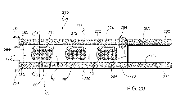
Referring now to FIGs. 20-22, an alternate embodiment of the
garment is shown, generally designated 270. Components shared with the
garments 10, 130, 170, 180, 190, 200, 240, 250 are designated with identical
reference numbers. A main feature of the garment 270 is that it performs a
temperature regulating function to space defined between the wearer's shirt
and an
overlying garment, such as a shirt, jacket, vest or the like. In this garment
270, a
liner panel 172 worn on the body has the first or outer surface 174 having at
least
one and preferably a plurality of pockets 60. At least one of the pockets 60
has an
internal pocket 80 (FIG. 21), making it a double pocket as described above in
the
previous embodiments. In the preferred embodiment, the pockets 60 are 9 inches
wide and 6 inches tall, and the pockets 80 are 6 inches wide and 4 inches
tall. It is
contemplated that these dimension are variable depending on the application,
and
that the pocket configuration may vary as described above in the other
embodiments. In the preferred embodiment, the panel 172 is generally
rectangular
and has an axial length sufficient to wrap around a majority of an
individual's
torso and/or waist (FIG. 22). Different lengths or sizes of the panel 172 are
contemplated to accommodate a variety of user torso sizes.
24
CA 03012043 2018-07-19
WO 2017/127290 PCT/US2017/013295
In the embodiment 270, the pockets 60, 80 are preferably made of a
porous polyester mesh material for enhanced temperature radiation from the
pockets, however other materials are contemplated. As is the case with the
embodiment of FIGs. 12 and 13a-13d, the panel 172 is worn with the pockets 60,
80 facing away from the user's body. As such, the inner surface 176 faces the
body. Accordingly, the panel 172 is preferably made of a soft, flexible
textile
material. Also, as is the case with the other embodiments, the pockets 60 are
dimensioned for accommodating temperature control elements, such as heating
packs, air-activated warmers, microwave warmed bags of IV fluid, cooling
packs,
phase change cooling elements, battery powered heating elements, battery
powered electric cooling fans, or the like.
In this embodiment, the temperature regulating element 62 is
preferably an air-activated warming pad, featuring known chemistry employing
the
heat generated from the exothermic oxidation of iron when exposed to air. More
specifically, air-activated warming pads typically contain cellulose, iron,
water,
activated carbon for evenly distributing heat, vermiculite as a water
reservoir and
salt as a catalyst to produce heat from the exothermic oxidation of iron when
exposed to air. Such pads emit heat for about 6 to 16 hours, depending on the
formulation and the permeability to air. Such pads 62 have been found to
generate
temperatures in the range of 130-150 F for at least as long as six hours.
Electrically powered heating elements 62 using batteries are also
contemplated,
generating temperatures in the range of 100-180 F depending on the voltage and
resistance and for varying durations depending on battery capacitance as is
known
in the art. Alternatively, if cooling is desired, the element 62 is optionally
a battery
powered electric fan or a cooling pack as referred to above.
Another feature of the embodiment 270 is that a layer or pad 272 of
insulative or heat resistant material, such as neoprene or the like is
positioned in
the pocket 60 adjacent the surface 174 and between the temperature control
element 62 and the surface 174. This positioning is designed to protect the
wearer
from the significant heat or cold generated by some types of temperature
control
elements 62.
CA 03012043 2018-07-19
WO 2017/127290 PCT/US2017/013295
Still another feature of the embodiment 270 is that the attachment
structure takes the form of the placement of upper and lower strips 274, 276
of
preferably VELCRO loop material along corresponding upper and lower edges
278, 280 of the panel 172. Other fastening materials or devices are
contemplated.
In the preferred embodiment slide adjusters 284 are fastened by a short
segment of
elastic strap 283 sewn in between the top and bottom edge 278, 280 VELCRO
loop material 274, 276 and the panel 172.
Attached to the panel 172 on upper and lower edges 278, 280
opposite to the side where the slide adjusters 284 are located are two elastic
straps
283 approximately 12 inches in length. Attached to the ends of the straps 283
are
3 inch length pieces of double sided VELCRO hook material 282. A further
component is a supplemental loop preferably an additional slide adjuster 284
sewn
in between the upper edge 278 strip of VELCRO loop material 274 and the panel
172. An optional component would be another slide adjuster 284 sewn in between
the lower edge 280 strip of VELCRO loop material 276 and the panel 172.
Instead of using a slide adjustor 284 in these locations, a supplemental belt
loop
288 made of textile, metal, or the like that is optionally used to maintain
the elastic
straps 283 in alignment with the upper and lower edge 278, 280 VELCRO loop
material 274, 276.
Since the elastic straps 283 have 3 inch long double-sided
VELCRO hook ends 282, additional flexibility is afforded in fastening the
panel
172 around a user's torso/waist. Either of the double-sided VELCRO hook ends
282 can be passed through the slide adjuster 284 on the opposite side and then
return to the side where it originated and attach to the upper or lower edge
278,
280 VELCRO loop material 274, 276. The upper edge 278 VELCRO double
hook end 282 would pass through the additional slide adjuster 284 before it
attaches to the upper edge 278 VELCRO loop material 274 on the side where the
elastic strap 283 originated. To accommodate a larger torso/waist, the elastic
straps 283 with their double sided VELCRO hook ends 282 can pass through the
slide adjusters 284 on the opposite side and then continue on to attach to the
upper
26
CA 03012043 2018-07-19
WO 2017/127290 PCT/US2017/013295
and/or lower edge 278, 280 VELCRO loop material 274, 276 on the opposite
side from where they originated.
It is contemplated that features of the particular embodiments shown
in FIGs. 1-22 are interchangeable, and that any of the described features of
one
embodiment can be used in combination with features of another embodiment.
While a particular embodiment of the present temperature regulating
garment has been described herein, it will be appreciated by those skilled in
the art
that changes and modifications may be made thereto without departing from the
invention in its broader aspects and as set forth in the following claims.
27