Note: Descriptions are shown in the official language in which they were submitted.
CA 03013362 2018-07-31
WO 2017/142886 PCT/US2017/017861
HIGH PRESSURE TEST PLUG
Cross-Reference to Related Applications
[0001] This application claims the benefit of priority of U.S. Provisional
Application No.
62/296,062, filed February 16, 2016, the entire contents of which are
incorporated herein by
reference.
Technical Field
[0002] The present disclosure relates to high pressure test plugs for the
facilitation of testing
pipelines subject to high backpressure loads.
Background
[0003] Pipelines are generally known to transport fluids (liquids or gases)
over a physical
distance within the internal cavities of the constituent individual pipe
sections. In order to test
the pipeline or to make occasional repairs or alterations to the pipeline, it
is disruptive and/or
undesirable to shut off the flow of fluid through the pipeline during the
period of testing or
repair. Rather, a plumbing technician will utilize a test plug, having a
diameter similar to the
inner diameter of the pipeline, to wholly or partially obstruct the pipeline.
Once obstructed,
testing or repairs may be performed downstream from the location where the
test plug is
obstructing the pipeline.
[0004] In certain applications involving a pipeline transporting fluids at
high backflow pressures,
there is an increased difficulty and risk with wholly or partially obstructing
the pipeline.
Namely, due to the higher pressure in the pipeline, traditional test plugs are
at a heightened risk
for failure resulting from the higher load it must withstand. The test plug
could experience an
"application failure" wherein the plug does not maintain its position within
the pipeline (i.e., it is
prone to sliding). Alternatively, the test plug could experience "design
failure", where the
materials of the plug will separate from one another. Depending on the type of
design failure,
damage to the pipeline and/or injuries to the plumbing technician are
possible. Existing test
1
CA 03013362 2018-07-31
WO 2017/142886 PCT/US2017/017861
plugs are insufficient for use in high backflow pressure pipelines because
they are structurally
unsound and prone to failure.
[0005] Therefore, there is a need for a test plug that is structurally adapted
for use with high
pressure pipeline, particularly around 150 pounds per square inch (psi). There
is further a need
for a test plug that can adequately be inflated to a high internal pressure
and maintain structural
integrity such that it may be used in a high backflow pressure pipeline.
[0006] The present invention provides a high pressure plug capable of
withstanding increased
loads and forces found in higher backflow pressure pipelines. In particular,
the invention relates
to a unique structure for a high pressure test plug that provides this
capability. The invention is
further capable of sustaining a sufficiently high internal pressure so as to
be capable of use in
these high backflow pressure pipelines, while also maintaining its structural
integrity to due to a
robust design.
[0007] The high pressure test plugs of the invention may be multi-size test
plugs which are
constructed and arranged to be inflated and used to seal interior portions of
pipelines, having a
specified diameter range, for testing, repair, and construction purposes. In
particular, the high
pressure test plugs of the invention may be expandable, multi-size high
pressure test plugs for
use in pipelines of various ranges, such as, for example, 4-8 inch inner-
diameter pipe ranges, 8-
12 inch inner-diameter pipe ranges, 12-16 inch inner-diameter pipe ranges, 20-
26 inch inner-
diameter pipe ranges, and 26-32 inch inner-diameter. The high pressure test
plugs of the
invention are preferably constructed of layered and reinforced elastomeric
materials, metal
endplates, metal rings, and an inflation member. The high pressure test plugs
may further
include a high pressure resistant flow-through conduit that is capable of
creating a bypass
through the high pressure test plug capable of withstanding the high inflation
pressure within a
chamber of the test plug.
Summary of the Invention
[0008] The present invention relates to an expandable plug structure for use
in high pressure
applications. The expandable plugs, such as pneumatic plugs, are preferably
constructed of a
multi-layered, reinforced elastomeric cylindrical body, i.e., of reinforced
natural rubber, and
having an inflator member at one end. The multi-layers include various rubber
layers, rubber
2
CA 03013362 2018-07-31
WO 2017/142886 PCT/US2017/017861
coated aramid, which subsequent to vulcanization provides a unitary plug with
shoulders that
resist delamination. The cylindrical body may incorporate metal end plates as
well as end plate
weldment structures which cooperate with a high pressure flow-through conduit
which allows
the completed high pressure test plug to simultaneously seal a pipeline and to
direct fluid
therethrough. The high pressure plug obtains its strength in part based upon
high frictional
resistance forces generated by the external rubber layer(s), and further by
the manner in which
the external rubber layer(s) are molded into the metallic structures in the
plug.
[0009] Further embodiments of the plug may additionally comprise biaxial nylon
cording.
[0010] A method of manufacturing non-high pressure test plugs may be generally
understood
with reference to U.S. Publication No. 2004/0216794, which disclosure is
incorporated herein by
reference.
[0011] A high pressure test plug according to a first embodiment seals a
pipeline transporting
fluids at high pressures. The test plug includes a tubular outer section
having a diameter D and
being generally elongate along an axis, the tubular outer section extending
between opposed first
and second ends having a length L defined therebetween as measured along a
first direction
parallel to the axis. The test plug includes first and second metal plates
disposed at the first and
second ends respectively, the first and second plates each defining a circular
body having an
outer diameter further defined by respective first and second outer edges,
wherein the first and
second plates are aligned along the axis. The test plug further includes first
and second metal
rings disposed at the first and second ends respectively, the first and second
rings each defining a
generally toroidal-shaped body having an exterior surface, the body further
having an inner
portion defining an inner diameter and an outer portion defining an outer
diameter that is
substantially equal to the outer diameter of each of the first and second
plates, the first and
second rings each being aligned along the axis, wherein the first ring is
disposed adjacent to the
first plate and the second ring is disposed adjacent to the second plate. The
test plug further
includes a rubber sheet partially defining the tubular outer section, the
rubber sheet having first
and second opposed sides, wherein a first part of the rubber sheet extends
from a centrally
disposed portion beyond the first and second outer edges of the plate, through
the inner portions
of the first and second rings, and a second part of the rubber sheet extends
around the respective
exterior surfaces and past the respective outer portions of the first and
second rings back toward
3
CA 03013362 2018-07-31
WO 2017/142886 PCT/US2017/017861
the centrally disposed portion, such that the first part of the rubber sheet
frictionally engages the
second part of the rubber sheet along a distance X measured along the first
direction, wherein the
distance X is greater than 5 inches. The test plug further includes a series
of rubber pads
connectable and securable to the first and second plates at the respective
first and second ends,
the series of rubber pads sealingly engaging the rubber sheet at the inner
portions of the first and
second rings so as to define a central chamber of the test plug, wherein the
central chamber is
configured to be inflated at a high pressure so as to stretch the rubber sheet
and thereby increase
the diameter D of the test plug.
[0012] In a further aspect of the invention, the distance X may be greater
than 5 inches but less
than 1/4 of the distance L. In yet a further aspect, the distance X may be
greater than 1/4 L but less
than 1/2 L. In another aspect, the distance X may be greater than 1/2 L, but
less than 1/2 L + 1/8 L.
In a further aspect, the distance X may be substantially equal to 1/2 L + 1/8
L.
Brief Description of the Drawings
[0013] Fig. 1 is a perspective view of a completed high pressure test plug in
accordance with a
first embodiment.
[0014] Fig. 2 is a side sectional view of the completed high pressure test
plug of Fig. 1.
[0015] Fig. 3 is a front view of a non-completed high pressure test plug in
accordance with the
first embodiment.
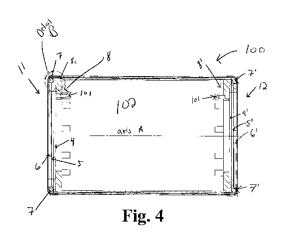
[0016] Fig. 4 is a longitudinal, cross-sectional view of the high pressure
test plug illustrated in
Fig. 3, taken along the line A-A as shown in Fig. 3.
[0017] Fig. 5 is a detailed view of a portion of the high pressure test plug
illustrated in Figs. 3-4,
showing the circular portion B illustrated in Fig. 4.
[0018] Fig. 6 is a side view of a non-completed high pressure test plug in
accordance with a
second embodiment.
[0019] Fig. 7 is a longitudinal, cross-sectional view of the high pressure
test plug illustrated in
Fig. 6, taken along the line A-A as shown in Fig. 6
[0020] Fig. 8 is a detailed view of a portion of the high pressure test plug,
illustrated in Figs. 4-5,
showing the circular portion B illustrated in Fig. 7.
4
CA 03013362 2018-07-31
WO 2017/142886 PCT/US2017/017861
Detailed Description of the Drawings
[0021] Figs. 1-2 depict a first embodiment of a high pressure test plug 100
for sealing a pipeline
transporting fluids at high pressures. The test plug 100 is sized and
configured to be inserted into
a pipeline so as to wholly or partially obstruct the flow of fluid through the
pipeline such that
testing, construction, or repairs may be performed on the pipeline downstream
from the test plug
100. Thus, the test plug 100 forms a tight, water-proof seal with an internal
surface area of the
pipeline, which is defined by an inner diameter of the pipeline. More
particularly, and as will be
discussed in greater detail below, the test plug 100 is adapted to wholly or
partially obstruct the
flow of fluid(s) through the pipeline that are flowing under "high pressures".
In a first aspect, it
is contemplated that the test plug 100 will be suitable to be used in
pipelines having high
backflow pressures, which are generally understood to be backflow pressures
greater than 100
pounds-per-square-inch ("psi"). The test plug 100 as described, however, may
be capable of use
in pipelines having backflow pressures in the pipeline of up to and including
150 psi. The test
plug 100 may further be capable of use in pipelines having backflow pressures
of as much as 250
psi, which will also be considered within the scope of the invention.
[0022] The embodiment of the test plug 100 illustrated in Figs. 1-2 is a
"completed" test plug,
ready to be installed in a pipeline. Notably, the test plug 100 in "completed"
form includes
endplate structures 110 and 120 and flow-through conduit 130, as will all be
discussed in greater
detail below.
[0023] Figs. 3-6 illustrate various views of the test plug 100 shown in Figs.
1-2, except prior to
installation of the endplate structures 110, 120, prior to installation of the
flow-through conduit
130, and prior to vulcanization of the test plug 100.
[0024] As illustrated particularly in Fig. 3, the test plug 100 has a
generally cylindrical shape.
The test plug 100 is elongate along axis A, which extends centrally through
the plug, from a first
end 11 to a second end 12. The test plug 100 includes a tubular outer section
that extends along
the axis A from the first end 11 to the second end 12 by a distance L along a
first direction that is
generally parallel to the axis A. The tubular outer section comprises a
plurality of elastomeric
(or rubber) layers¨internal rubber layer 1, rubber sheet 2, and external
rubber layer l'¨
disposed one on top of the other (see Fig. 5).
CA 03013362 2018-07-31
WO 2017/142886 PCT/US2017/017861
[0025] Referring first to Fig. 3, the test plug 100 defines an outer diameter
D1 as shown. In
order to create a tight seal with the internal surface area of the pipeline,
the diameter D1 will be
increased upon inflation of the test plug 100 to closely match the inner
diameter of the pipeline.
As will be explained in further detail below, the test plug 100 is configured
to be inflated so as to
define a multi-range test plug. In other words, the test plug 100 may be
inflated such that the
diameter D1 of the plug may be increased by, for example, 4-6 inches, to
conform to a greater
range of internal diameters of the pipeline, although other ranges of
inflation are contemplated.
This provides the benefit that a single-size test plug 100 may be versatile to
accommodate many
differently sized pipes up to a maximum inflation diameter D1 for a given
plug. Another
benefit is that inflating the test plug 100, thereby increasing the diameter
D1 will enable the test
plug 100 to conform to any number of surface irregularities on the internal
surface area of the
pipeline in order to provide the necessary water-proof seal.
[0026] As further illustrated in Fig. 3, the first end 11 of the test plug 100
defines a first metal
plate 8. The first metal plate 8 may be made of steel, or any other suitable
metal having similar
strength characteristics known in the art may be substituted without departing
from the scope of
the invention. The first metal plate 8 defines a first circular body having an
outer diameter 0D1
and an inner diameter as shown, wherein the outer diameter 0D1 of the first
metal plate 8 is
further defined by a first outer edge 8c (see Fig. 4). The first metal plate 8
includes a plurality of
apertures 8a disposed around a periphery of an outer-facing surface 8b of the
first metal plate 8.
The apertures 8a are configured to receive a plurality of complementary bolts
101 (see Fig. 4) so
as to positionally fix the endplate structure 110 (see Figs. 1-2) so as to
seal the test plug 100. As
shown in Fig. 4, the test plug 100 at the first end 11 further includes a
series of elastomeric (e.g.,
rubber) pads 4, 5, and 6 (see Fig. 4) so as to facilitate the seal of the test
plug 100 when the
endplate structure 110 is bolted onto the plate 8 by bolts 101. Although as
illustrated in Fig. 1,
the first metal plate 8 includes six apertures 8a, it is contemplated that any
number of apertures
may be used to seal the endplate structure 110 to the first end 11 of the test
plug 100. It is further
contemplated that the first metal plate 8 may contain no apertures 8b and may
instead include
other sealing mechanisms so as to effectively seal the endplate structure 110
to the first end 11.
Such sealing mechanisms may include, but are not limited to glues, sealants,
clips, fasteners, or
any other suitable sealing mechanism known in the art. While the elastomeric
pads 4, 5, and 6
will ideally comprise rubber, it is further contemplated that the elastomeric
pads 4, 5, and 6 may
6
CA 03013362 2018-07-31
WO 2017/142886 PCT/US2017/017861
comprise any other elastomeric material having similar structural
characteristics to rubber
without departing from the scope of the invention.
[0027] Fig. 4 depicts a longitudinal, cross-sectional view of the test plug
100 shown in Fig. 3.
As illustrated, the cross section is taken along lines A-A shown in Fig. 3. As
shown in Fig. 4,
the second end of test plug 12 defines a second metal plate 8' having a
similar configuration to
the first metal plate 8. The second metal plate 8' may be made of steel, or
any other suitable
metal having similar strength characteristics known in the art may be
substituted without
departing from the scope of the invention. The second metal plate 8' defines a
second circular
body having an outer diameter 0D1', wherein the outer diameter 0D1' of the
second metal plate
8 is further defined by a second outer edge U. The second plate 8' also
includes a plurality of
apertures (not shown) that are configured to receive a plurality of
complementary bolts 101 so as
to positionally fix endplate structure 120 so as to seal the test plug 100 at
the second end 12. The
test plug 100 at the second end 12 further includes a series of elastomeric
(e.g., rubber) pads 4',
5', and 6' in order to facilitate sealing the second end 12 of the test plug
100 with the endplate
structure 120 (see Figs. 1-2). With both the first end 11 and second end 12
sealed by the series
of elastomeric pads 4, 5, 6 and 4', 5', and 6' (respectively), along with the
endplate structures
110 and 120, the test plug 100 defines an inner chamber (or cavity) 102 (see
Fig. 4). While the
elastomeric pads 4', 5', and 6' will ideally comprise rubber, it is further
contemplated that the
elastomeric pads 4', 5', and 6' may comprise any other elastomeric material
having similar
structural characteristics to rubber without departing from the scope of the
invention.
[0028] An inflation port (not illustrated) may be selectively inserted into
one of the first and
second ends 11, 12 of the test plug 100 (such as, for example, through the
endplate structures 110
or 120, shown in Figs. 1-2) so as to provide a passageway into the inner
cavity 102. The
inflation portion may be used to fill the inner cavity 102 with an inflation
medium such as water
to obtain an internal pressure in the cavity 102 of up to 200 psi. It is
contemplated that the cavity
102 of the test plug 100 may be filled to other pressures as may become
necessary in a given
plumbing application, including up to and including 250 psi. It is further
contemplated that the
cavity 102 of the test plug 100 may be inflated with air, water, or some other
medium known in
the art to cause the diameter D1 of the test plug 100 to increase to the
desired inner diameter of
7
CA 03013362 2018-07-31
WO 2017/142886 PCT/US2017/017861
the pipeline, such that the inner diameter of the pipeline is less than or
equal to Dlmax, as
described above.
[0029] With continuing reference to Fig. 4, the test plug 100 additionally
comprises first and
second metal rings 7 and 7' disposed at the respective first and second ends
11 and 12 when the
test plug 100 is in an assembled configuration. The first and second metal
rings 7, 7' each have a
generally toroidal-shaped body defining an exterior surface. The toroidal-
shaped body of each
ring 7 and 7' defines a circular cross section that is swept about a circle
having a center that is
disposed on the axis A when the test plug 100 is in the assembled
configuration. The rings 7 and
7' each have an inner portion defining an inner diameter and an outer portion
defining an outer
diameter that is substantially equal to the outer diameter 0D1 of each of the
first and second
plates 8, 8'. Importantly, the first and second metal rings 7, 7' are
"floating" with respect to the
first and second plates 8, 8' and with respect to one another. In other words,
the first and second
metal rings 7 and 7' are not positionally fixed relative to one another or to
either of the metal
plates 8 and 8'. This aspect allows the first and second metal rings 7, 7' to
alter their position(s)
or orientation(s) as needed to distribute excessive or imbalanced internal or
external pressures on
the test plug 100. The first and second metal rings 7, 7' may be made of
welded steel, or any
other suitable metal having similar strength characteristics known in the art
may be substituted
without departing from the scope of the invention.
[0030] With reference now to Fig. 5, a portion of the test plug 100 indicated
by the detail circle
B near the first end 11, (see Fig. 4) is illustrated in greater detail. As
shown in Fig. 5, the
plurality of rubber layers 1, 2, and 1' of the tubular outer section are
partially disposed on top of
a cardboard tube 3. As will be described in greater detail below, the
cardboard tube 3 facilitates
manufacturing of the test plug 100. With continuing reference to Figs. 4-5,
cardboard tube 3
defines an inner-most layer of the tubular outer section of the test plug 100
relative to the axis A.
The cardboard tube 3 has a cylindrical body that extends between the first
metal plate 8 at the
first end 11 to the second metal plate 8' at the second end 12. Moving
outwardly from the axis
A, inner rubber layer 1 is disposed on top of the cardboard tube 3; the inner
rubber layer 1 having
a cylindrical body that extends along the first outer edge 8, of the first
metal plate 8, along the
cardboard tube 3, and along the second outer edge 8,' of the second metal
plate 8'.
8
CA 03013362 2018-07-31
WO 2017/142886 PCT/US2017/017861
[0031] Moving further outwardly from the axis A and with continuing reference
to Fig. 5, rubber
sheet 2 is disposed on top of inner rubber layer 1. Rubber sheet 2 defines a
cylindrical sleeve
having first and second opposed sides 2', 2". The rubber sheet 2 comprises an
aramid fiber
material 2a built into the rubber sheet 2. The aramid fiber material 2a
comprises a series of
aligned, parallel aramid fibers which provide an additional measure of
structural integrity to the
rubber sheet 2 when the rubber sheet 2 is subjected to excessive or imbalanced
internal or
external pressures on the test plug 100. The individual aramid fibers
generally extend from the
first end 11 to the second end 12 of the test plug 100 when the test plug 100
is in the assembled
configuration. In an embodiment, the fibers may extend along a direction that
is parallel to the
first direction. As shown in Fig. 5, the first side 2' of the rubber sheet 2
may abut an outer
surface of the inner rubber layer 1. The rubber sheet 2 may extend along a
second direction,
substantially opposite the first direction, beyond the first plate 8 and
toward the first end 11 of
the test plug 100. The rubber sheet 2 may further extend downwardly and
through the inner
portion of the first metal ring 7. It may then wrap around the first metal
ring 7 such that the
second side 2" abuts the exterior surface of the first metal ring 7. The
rubber sheet 2 may then
extend past the outer portion of the first ring 7 and back along the first
direction such that the
second side 2" of the rubber sheet 2 extends along and on top of the second
side 2" of the
rubber sheet 2 at an engaged portion 2", which itself extends along the second
direction as
described above. In other words, the rubber sheet 2 extends along the rubber
layer 1, through the
ring 7, and back onto itself.
[0032] With reference now to Fig. 4, the rubber sheet 2 extends back onto
itself at the engaged
portion 2', such that a first part of the rubber sheet 2 (on the second side
2") sheet frictionally
engages a second part of the rubber sheet 2 (also on the second side 2") at
the engaged portion
2' for a distance X measured along the first direction. The distance X is
generally greater than
4 or 5 inches, and it may be 1/4 of the total length L of the test plug 100.
The distance X may be
up to 1/2 of the total length L of the test plug 100 (1/2 L), such that the
portions of the rubber
sheet 2 extending from the first end 11 and the second end 12 of the test plug
100 meet in a
central location along the tubular outer section so as to overlap one another
at the central
location. In yet another aspect, X may represent a distance 1/2 L + 1/8 L,
such that the degree of
overlap as described previously is further increased so as to further increase
the frictional
strength at the engaged portion 2". Different distances X as described above
are all
9
CA 03013362 2018-07-31
WO 2017/142886 PCT/US2017/017861
contemplated within the scope of the invention. As explained in greater detail
below, the
distance X is importantly tied to the frictional force imparted on the rubber
sheet 2, which is to
say that the increased frictional force is directly proportional to an
increased value of the distance
X.
[0033] Finally, and moving further outwardly from the axis A, and with
reference to Fig. 5, the
outer rubber layer 1 is disposed on top of the first side 2' of the rubber
sheet.
[0034] Referring once again to Fig. 4, although not shown in a detailed view,
the second end 12
of the test plug 100 embodies the same characteristics, arrangement, and
structurally connectivity
with regard to the rubber layer 1, the rubber sheet 2, and the outer rubber
layer 1' as described
above with respect to the first end 11.
[0035] The engaged portion 2" serves a very important role in the test plug
100 to maintain the
structural integrity of the test plug 100 when it is subjected to excessive or
imbalanced internal
and external pressures. Due to the proportion of the distance X being
generally greater than 1/4 of
the total length L, the frictional force between the engaged second sides 2",
2" of the rubber
sheet 2 can amount to a significant impedance to the separation of the rubber
sheet 2 or the
adjacent rubber layers 1, l' from the outer tubular section of the test plug
100. This force, in
parts, helps prevent the failure of the test plug 100 when it is subjected to
excessive internal and
external forces. As the total internal volume of the test plug increase with
inflation¨or as it
increases with choice of larger diameter test plugs, as described further
below in the second
embodiment¨the internal pressure can pose a significant safety concern. In
addition to the
frictional force obtained by virtue of the engaged portion 2", significant
structural integrity is
provided to the rubber sheet 2 by virtue of the metal rings 7 and 7'. More
specifically, because
the rubber sheet 2 extends through and around the metal rings 7 and 7',
further mechanical,
structural integrity is imparted to the test plug 100 to resist failure due to
the application of
excessive internal and external pressure. For example, when the inner cavity
102 of the test plug
100 is inflated with water up to 200 psi, the diameter D1 of the test plug 100
is increased, causing
the inner rubber layer 1, rubber sheet 2, and outer rubber layer l' to stretch
and expand. Because
rubber sheet 2 is wrapped through and around the metal rings 7 and 7', the
rubber sheet 2 is
clamped by the metal to further and additionally resist separation from the
test plug 100. In
combination, the frictional force imparted by the engaged portion 2" and the
rubber sheet 2
CA 03013362 2018-07-31
WO 2017/142886 PCT/US2017/017861
clamped by the metal rings 7 and 7', the test plug 100 is more failure
resistant when utilized in
high pressure pipelines in plumbing applications.
[0036] Referring to Fig. 4, the series of elastomeric pads 4, 5, and 6 at the
first end 1, and 4', 5',
and 6' at the second end, are fitted onto the first and second metal plates 8
and 8' and are bolted
to the metal plates 8, 8' (as discussed above) to form a tight water-proof
seal and to create the
cavity 102. The series of elastomeric pads 4, 5, 6, 4', 5', and 6'
additionally function to "top off'
the first and second ends 11, 12 so as to make them flush with the rubber
sheet 2 (as it wraps
around the metal rings 7, 7') and the outer rubber layer 1' disposed on the
rubber sheet 2. In
other words, the addition of the elastomeric pads at each of the first and
second ends 11, 12
square the ends away with the rubber materials forming the outer tubular
section to result in a
relatively smooth and even outer surface area of the test plug 100.
[0037] Referring back now to Figs. 1-2, the "completed" test plug 100 having
the endplate
structures 110 and 120 and the flow-through conduit 130. The flow-through
conduit 130
provides an internal passageway through the completed test plug 100 after it
has been sealed by
endplate structures 110 and 120. The flow-through conduit 130 functions as a
bypass to allow a
controlled amount of fluid, as determined by the plumbing technician, to pass
through the test
plug 100 as needed in a given testing, repair, or construction operation while
utilizing the
inflated test plug 100. As shown particularly in Fig. 2, the flow-through
conduit 130 is
reinforced with spring member 131. Spring member 131 structurally reinforced
the passageway
in the flow-through conduit 130 such that when the cavity 102 of the test plug
100 is filled with
water (or other inflation medium) up to the 200 psi pressure level, the flow
through conduit 130
will not collapse or otherwise be affected by the high pressure.
[0038] Figs. 6-8 depict a second embodiment of a high pressure test plug 200
for sealing a
pipeline transporting fluids at high pressures, the test plug 200 having an
outer tubular section
and being elongate along an axis B. The test plug 200 is structurally similar
to the test plug 100
as described above, with some exceptions as will be noted below.
[0039] Unlike the test plug 100, test plug 200 of the second embodiment has a
larger diameter
D2, as shown in Fig. 6. Thus, as shown in Fig. 7, the internal cavity 102'
represents a larger
volume than the internal cavity 102 of the first embodiment of the test plug
100. Because the
test plug 200 is still inflated with the same pressure of 200 psi in order to
increase the diameter
11
CA 03013362 2018-07-31
WO 2017/142886 PCT/US2017/017861
D2 to the inner diameter of the pipeline (up to D2max), the total force
exerted on the test plug 200
will be greater than that of test plug 100. As such, additional reinforcement
structures may be
employed, as will be described below, to maintain the structural integrity of
the test plug 200.
[0040] With reference now to Figs.7-8, the test plug 200 includes first and
second metal plates
80, 80' at respective first and second ends 111 and 112. With particular
reference to Fig. 8, the
test plug 200 includes two metal rings 70, 71. The rings, like the rings 7,
7', are toroidal-shaped
and each define an inner portion, an exterior surface, and an outer portion.
The rings 70, 71 each
have an outer diameter and an inner diameter with respect to the axis B. As
shown, the ring 71
has a smaller outer diameter than the ring 70, and the rings are
concentrically disposed relative to
one another about the axis B. The rings 70, 71 are integrally connected to one
another by
welding at various locations about the periphery of the rings.
[0041] Similar to the test plug 100 as described above, the test plug 200 may
include various
layers of rubber that form the outer tubular section. Starting closest to the
axis B and working
outwardly away from the axis B, the outer tubular section of test plug B may
include inner
rubber 10, rubber sheet 20, and outer rubber layer 10'. Similar to the test
plug 100, as shown in
Fig. 8, the rubber sheet 20 may extend along the inner portion of ring 71,
around the exterior
surfaces of both rings 70, 71 and around the outer portion of ring 70, such
that the rubber layer
20 extend back on top of itself so as to create an engaged portion 20'.
Similar to the engaged
portion 20' described above with regard to the test plug 100, the engaged
portion 20" 'will
manifest a frictional engagement of a second part of the rubber sheet 20 with
a first part of the
rubber sheet 20 at the engaged portion 20' for a distance Y measured along a
third direction
defined by the axis B. The distance Y is generally greater than 4 or 5 inches,
and it may be 1/4 of
the total length L2 of the test plug 200. The distance Y may alternatively be
up to 1/2 of the total
length L2 of the test plug 200, such that the portions of the rubber sheet 20
extending from the
first end 111 and the second end 112 of the test plug 200 meet in a central
location along the
tubular outer section so as to overlap one another at the central location. In
yet another aspect, Y
may represent a distance 1/2 L2 + 1/8 L2, such that the degree of overlap as
described previously
is further increased so as to further increase the frictional strength at the
engaged portion 20".
Different distances Y as described above are all contemplated within the scope
of the invention
in relation to the second embodiment of test plug 200.
12
CA 03013362 2018-07-31
WO 2017/142886 PCT/US2017/017861
[0042] Similar to the test plug 100, in the test plug 200, the engaged portion
20" serves a very
important role of maintaining the structural integrity of the test plug 200
when it is subjected to
excessive or imbalanced internal and external pressures. Due to the proportion
of the distance Y
being generally greater than 1/4 of the total length L2, the frictional force
generated by the
engaged portion 20" can amount to a significant impedance to the separation of
the rubber sheet
20 or the adjacent rubber layers 10, 10' from the outer tubular section of the
test plug 200. This
force, in parts, helps prevent the failure of the test plug 200 when it is
subjected to excessive
internal and external forces. As the total internal volume of the test plug
increase with
inflation¨or as it increases with choice of larger diameter test plugs, as
described further below
in the second embodiment¨the internal pressure can pose a significant safety
concern. In
addition to the frictional force obtained by virtue of the engaged portion
20", significant
structural integrity is provided to the rubber sheet 20 by virtue of the metal
rings 70 and 71.
More specifically, because the rubber sheet 20 extends through and around the
metal rings 70,
71, further mechanical, structural integrity is imparted to the test plug 100
to resist failure due to
the application of excessive internal and external pressure. For example, when
the inner cavity
102' of the test plug 200 is inflated with water up to 200 psi, the diameter
D2 of the test plug 200
is increased, causing the inner rubber layer 10, rubber sheet 20, and outer
rubber layer 10' to
stretch and expand. Because rubber sheet 20 is wrapped through and around the
metal rings 70,
71, the rubber sheet 20 is clamped by the metal to further and additionally
resist separation from
the test plug 200. In combination, the frictional force imparted by the
engaged portion 20" ' and
the rubber sheet 20 clamped by the metal rings 70, 71, the test plug 200 is
more failure resistant
when utilized in high pressure pipelines in plumbing applications.
[0043] The addition of two rings 70, 71 in the test plug 200 may be important
to increase the
structural rigidity of the test plug 200. Due to the strength characteristics
of the metal material of
the rings 70, 71, which may be steel, the clamping effect described above may
be even stronger
to resist separation of the rubber sheet 20 from the test plug 200 under
extreme pressure
conditions.
13