Note: Descriptions are shown in the official language in which they were submitted.
CA 03013364 2018-07-31
WO 2017/151532 PCT/US2017/019809
1
MASKING APPLICATOR FOR FEMININE CARE PRODUCT
FIELD OF THE INVENTION
The present invention relates generally to an applicator having preferred
masking
properties, more specifically to applicators for feminine hygiene products.
BACKGROUND OF THE INVENTION
Feminine care products, such as tampons and pessaries, are generally used by
women
within the vagina, such as, e.g., to absorb menstrual or other body exudates,
for pelvic support,
and/or for other feminine needs. Such feminine products can be inserted into
the vagina
digitally, such as, e.g., by using a finger, or can be inserted into the
vagina by using an applicator.
Applicators typically comprise an insertion member and a plunger. The material
to be
expelled from the applicator, such as an absorbent tampon or pessary, can be
positioned within
the insertion member. The insertion member can have a first end for insertion
of the material and
a second end for receipt of the plunger. To use the applicator, the consumer
will grasp the
insertion member, position the first end appropriately, such as, e.g., into
the body, and move the
plunger in the insertion member towards the first end to insert the material.
During the insertion process, the applicator often comes in contact with
menses or blood.
The menses or blood may remain on the outer surface of the applicator as the
user removes the
applicator from the body and becomes visible to the user.
Applicators can be made up of different materials. For example, currently
available in
market there are applicators which comprise cardboard and applicators which
comprise plastic.
Plastic applicators come in different colors deemed consumer appealing
including green and
blue. Traditionally, cardboard Applicators are white and do not mask the
appearance of menses
or blood that is placed on the surface of the Applicators. Further, many
plastic applicators come
in colors that, when placed in contact with bodily fluids such as blood or
menses, also do not
mask the appearance of the blood or menses. However, to many, the sight of
blood is
unappealing. Further, the appearance of the applicator may become unattractive
due to the
combination of the applicator and the bodily fluids, when visually combined.
Based on the foregoing, it would be desirable to provide an applicator that is
aesthetically
appealing to the consumer and masks the appearance of any blood or menses that
may end up on
its surface during the insertion process.
SUMMARY OF THE INVENTION
CA 03013364 2018-07-31
WO 2017/151532 PCT/US2017/019809
2
A feminine care product having an applicator comprising a barrel portion and a
plunger
slidingly engaged, wherein the barrel portion comprises an insertion end, a
grip end, an insertion
portion, a grip portion, and a first L* value of between 5 and 30.
An array of feminine care products having a first product having a first
applicator and a
second product having a second applicator, wherein each of the first
applicator and second
applicator comprise a barrel portion comprising an insertion end and a grip
end disposed opposite
the insertion end of the barrel portion; and a plunger slidingly engaged with
the barrel portion;
wherein the barrel portion and the plunger of each of the first applicator and
second applicator
comprise a polyolefin resin, wherein the first applicator comprises a first
color, wherein the
second applicator comprises a second color, wherein each of the first
applicator and the second
applicator comprise a onset crystallization temperature and an L* of between 5
and 50, and
wherein the onset crystallization temperature of the first applicator and the
onset crystallization
temperature of the second applicator differ by less than 0.4 degrees Celcius.
BRIEF DESCRIPTION OF THE DRAWINGS
Fig. 1 is a plan view of an applicator comprising a barrel and a plunger.
Fig. 2 is a DSC curve with Calculated Onset Temperature of Crystallization
(OTX).
DETAILED DESCRIPTION OF THE INVENTION
As used herein, "array" means a display of packages comprising disposable
articles of
different sizes having like article constructions (e.g., same elastomeric
materials [compositionally
and/or structurally] in the flaps, graphic elements) said packages having the
same brand and/or
sub-brand, and said packages oriented in proximity to each other in a given
area of a retail store.
An array is marketed as a line-up of products normally having like packaging
elements (e.g.,
packaging material type, film, paper, dominant color, design theme, etc.) that
convey to
consumers that the different individual packages are part of a larger line-up.
Arrays often have
the same brand, for example, "Always," and same sub-brand, for example,
"Radiant." A different
array may have the brand "Always" and the sub-brand "Pearl." Furthermore, the
packaging may
be distinctly different. Arrays also often have the same trademarks, including
trademarks of the
brand, sub-brand, and/or features and/or benefits across the line-up. "On-line
Array" means an
"Array" distributed by a common on-line source.
CA 03013364 2018-07-31
WO 2017/151532 PCT/US2017/019809
3
As used herein, the term "feminine care product" includes absorbent articles
useful for
feminine needs, such as articles that typically can be intended for feminine
use internally, such
as, e.g., within a user's vagina. Internal feminine care products can include,
for example,
tampons and pessaries.
As used herein, the term "pessary" refers to any type of substantially non-
absorbent
structure for the purpose of reducing urine leakage and/or supporting a
prolapsed uterus and/or
bladder. Such pessaries can have any variety of shapes and sizes including
cylinder, ovate,
spherical, tubular, annual rings, "U" shaped, cup shaped, rings, cubes or
donut shaped, and can
function in any suitable manner, such as, e.g., by direct application of
support, lever force,
expansion of the device by selection of material, and/or by inflation of the
device.
As used herein, the term "vaginal canal" refers to the internal genitalia of
the human
female in the pudendal region of the body. The terms "vaginal canal" or
"within the vagina" as
used herein are intended to refer to the space located between the introitus
of the vagina
(sometimes referred to as the sphincter of the vagina) and the cervix.
As used herein "applicator" refers to a device or implement that facilitates
the insertion of
a tampon, medicament, pessary, treatment device, visualization aid, or other
into an external
orifice of a mammal, such as the vagina, rectum, ear canal, nasal canal, or
throat. Non-limiting
specific examples of such include any known hygienically designed applicator
that is capable of
receiving a tampon may be used for insertion of a tampon, including the so-
called telescoping,
tube and plunger, and the compact applicators, an applicator for providing
medicament to an area
for prophylaxis or treatment of disease, a spectroscope containing a
microcamera in the tip
connected via fiber optics, a speculum of any design, a tongue depressor, a
tube for examining
the ear canal, a narrow hollow pipe for guiding surgical instruments, and the
like.
As used herein, "compression" refers to the process of pressing, squeezing,
compacting or
otherwise manipulating the size, shape, and/or volume of a material to obtain
a tampon having a
vaginally insertable shape. The term "compressed" refers to the state of a
material or materials
subsequent to compression. Conversely, the term "uncompressed" refers to the
state of a material
or materials prior to compression. The term "compressible" is the ability of a
material to undergo
compression.
The term "cross-section" as used herein, is any 5 mm thick section of the
tampon
orthogonal to the longitudinal axis.
CA 03013364 2018-07-31
WO 2017/151532 PCT/US2017/019809
4
As used herein, "fluid wicking" refers to the ability of a material to carry
fluid or moisture
by capillary action. The fluid wicking capacity of a medium may be measured by
grams of fluid
drawn per gram of tampon weight over a fixed period of time.
The term "folded" as used herein, is the configuration of the tampon pledget
that may be
incidental to lateral compaction of the absorbent material or may purposely
occur prior to a
compression step. Such a configuration is readily recognizable, for example,
when the absorbent
material abruptly changes direction such that one part of the absorbent
material bends and lies
over another part of the absorbent material.
As used herein, "generally cylindrical" refers to the usual shape of tampons
as is well
known in the art, but which also includes oblate or partially flattened
cylinders, curved cylinders,
and shapes which have varying cross-sectional areas (such as a CokeTM bottle
shape). The
longitudinal axis refers to the longest linear dimension of the tampon. The
cross-section refers to
a slice taken at right angles to the longitudinal axis.
As used herein, the term "insertion end" refers to the portion of the tampon
or applicator
including the end that is intended to enter the vaginal canal first when
inserting the tampon or
applicator into the vaginal canal.
As used herein, the term "longitudinal axis" of a tampon refers to the axis
that runs
through the center of the tampon as shown in FIG. 1. A portion of the tampon
may be
asymmetric about the longitudinal axis, such as when the withdrawal end region
is flared and
distorted from the original shape of the rest of the tampon (such as a "fin
shape"). Further, the
longitudinal axis may be linear or non-linear.
As used herein, "overwrap" refers to the liquid pervious material covering the
exterior
surface of the absorbent member. The overwrap may permeate the inner region of
a compressed
absorbent member. The overwrap may extend below the withdrawal end to form a
skirt portion.
The overwrap may be fluid wicking. The overwrap, as defined herein, may
possess a horizontal
wicking capacity of at least about 2, alternatively from about 3 to about 6
grams of fluid per gram
of tampon at a 500 second interval. Suitable overwraps are disclosed in
greater detail in U.S.
Patent No. 6,840,927 and U.S. Patent No. 7,112,192, filed November 18, 2002,
entitled "Tampon
With an Overwrap or Overwraps Having Both Masking and Wicking Properties,"
issued to
Hasse, et al.
CA 03013364 2018-07-31
WO 2017/151532 PCT/US2017/019809
As used herein, the term "tampon," refers to any type of absorbent structure
that is
inserted into the vaginal canal or other body cavities for the absorption of
fluid therefrom, to aid
in wound healing, or for the delivery of active materials, such as
medicaments, or moisture.
The "outer surface" of a tampon refers to the visible surface of the
(compressed and/or
5 shaped) tampon prior to use and/or expansion. At least part of the outer
surface may be smooth or
alternatively may have topographic features, such as ribs, spiraling ribs, a
mesh pattern, or other
topographical features. Typically, tampons are constructed from an absorbent
material, which has
been compressed and/or shaped in any or all of the width direction, the radial
direction, and the
axial direction, in order to provide a tampon which is of a size and stability
to allow insertion
within the vagina or other body cavity.
As used herein, the term "radial axis" of a tampon refers to the axis that
runs at right
angles to the longitudinal axis of the tampon as shown in FIG. 1.
The term "rolled," as used herein, is the configuration of the tampon pledget
after
winding the absorbent material upon itself.
The term "vaginally insertable shape" as used herein refers to the geometrical
form of the
absorbent tampon after compression. The tampon may be compressed into a
generally cylindrical
configuration in the radial direction along the longitudinal and/or lateral
axes, axially, or in both
the radial and axial directions. An example of a typical compressed tampon may
be one which
may be about 10-16 mm wide and about 40- 50 mm long depending on the level of
absorbency.
While the tampon may be compressed into a substantially cylindrical
configuration, other shapes
are possible. These may include shapes having a cross section that may be
described as
rectangular, trapezoidal, seni-circular, hourglass, or other suitable shapes.
As used herein, the term "withdrawal end" refers to the portion of the
applicator opposite
the insertion end.
As used herein, "cm" is centimeter, "mm" is millimeter, "g" is gram, "gsm" is
grams per
meter squared, "dpf" is denier per fiber, "g/g" is gram of fluid per gram of
sample, "wt" is weight,
"psi" is pound per square inch.
While particular embodiments have been illustrated and described, it would be
obvious to
those skilled in the art that various other changes and modifications can be
made without
departing from the spirit and scope of the invention.
The array of applicators described herein use two or more polymer resins
having an onset
crystallization temperature that is within 0.4 degrees Celsius of the other
polymer resins. Each of
CA 03013364 2018-07-31
WO 2017/151532 PCT/US2017/019809
6
the applicators has an opacity of greater than 50%. The applicators may be a
typical "tube and
plunger" type arrangement and may be plastic or other suitable material.
Additionally, a
"compact" type applicator is also suitable. Where the tampon is shaped and
provides aesthetic
appeal to consumers, it is may be desirable to combine the shaped tampon with
an applicator type
which enables the user to observe at least a portion or the whole shape of the
shaped tampon.
Two techniques which allow the user to better notice the shape of the tampon
are to either make
visual observation possible through the use of a translucent or even
transparent applicator
materials, or to provide a tampon applicator insertion end that better follows
and hence better
displays the profiled shape of the enclosed shaped tampon than the typical
commercial tampon
applicators comprising straight-walled cylindrical inserter tubes often made
from molded plastic
or laminated cardboard tubes. The applicator may be flushable as described in
U.S. Pat. No.
6,730,057, filed March 16, 2001, entitled "Flushable Tampon Applicators,"
issued to Zhao, et al.
The applicator may be corrugated as described in U.S. Pat. No. 7,066,870,
filed Jun 25, 2002,
entitled "Method of Producing a Corrugated Tampon Applicator," issued to
Fedyk, et al.
The applicator may have a grip region as described in U.S. Pat. Nos.
8,303,558;
7,081,110; 8,449, 491; or 8,075,512. The applicator may have an absorbency
indicator as
described in U.S. Pat. No. 7,166,101, filed December 9, 2005, entitled "Tampon
Outer Surface
Having Increasing Number of Written Identifiers to Indicate Absorbency,"
issued to Denti, et al.
The grip region may have visual indicia. Any visual indicia suitable from
distinguishing the grip
portion from the barrel portion and/or the plunger can be used, such as, e.g.,
color, such as, e.g., a
contrasting color and/or a coordinating color, sheen, such as, e.g., a glossy
or matte finish,
shimmer, any type of mark, figure, picture, identification code, symbol, icon,
pattern, text, such
as, e.g., a word, number, nomenclature, sentence, or instruction, line, line
segment, curved line,
band, arrow, area of coloration, or any other printed indicia having a purpose
of providing a
signal or guide to the user.
The tube or barrel portion can be constructed from any suitable material.
Suitable
materials include, for example, any combinations thereof, polyethylene,
polypropylene,
polybutylene, polystyrene, polyvinylchloride, polyacrylate, polymethacrylate,
polyacrylonitrile,
polyacrylamide, polyamide, nylon, polyimide, polyester, polycarbonate,
polylactic acid,
polyhydroxyalkanoate, ethylene vinyl acetate, polyurethane, silicone,
thermoplastic starch, trans-
poly isoprene, derivatives thereof, copolymers thereof, mixtures thereof, or
any suitable smooth
plastic material. Examples of suitable materials are disclosed in, e.g., U.S.
Pat. Nos. 5,346,468
and 5,558,631. In certain embodiments, additives can be included in the
material to alter or
enhance certain material properties. Suitable additives include, for example,
mold release agents,
CA 03013364 2018-07-31
WO 2017/151532 PCT/US2017/019809
7
slip agents, surface energy modifiers, inorganic fillers and/or any other
suitable additives. In
certain embodiments, the barrel portion can be coated with a substance to give
it a high slip
characteristic, such as, e.g., with wax, polyethylene, a combination of wax
and polyethylene,
cellophane, clay, and other lubricants that can facilitate comfortable
insertion.
The barrel portion can be sized and configured to house a feminine hygiene
product, such
as, e.g., an absorbent tampon and/or pessary. In certain embodiments, the size
of the barrel
portion can be determined primarily by the dimensions of the feminine hygiene
product. For
example, the barrel portion can have inner diameters of about 5.0 millimeters
to about 22.0
millimeters and a wall thickness of about 0.2 millimeter to about 2.0
millimeters. The inner
diameter of the barrel portion can be greater than the diameter of the
feminine hygiene product to
prevent the barrel portion from interfering with the expulsion of the feminine
hygiene product
from the barrel portion. In certain embodiments, the inner diameter of the
barrel portion can
have varying diameters and shapes to conform to the profiled shape of the
enclosed feminine
hygiene product, such as, e.g., a tampon. The barrel portion can have a length
sufficient to house
the feminine hygiene product prior to the expulsion of the feminine hygiene
product from the
applicator into the vagina.
The barrel portion can be of any suitable cross-sectional shape. In certain
embodiments,
the barrel portion can include a generally non-circular cross-sectional shape,
such as, e.g., oval,
rectangular, elliptical, oblate, or other suitable shapes. The barrel portion
can have a cross-
sectional shape that has a greater thickness than width or vice versa. In
certain embodiments, the
barrel portion can have a substantially uniform cross-section, such as, e.g.,
having the same
cross-section along the length. In other embodiments, the barrel portion can
have varying cross-
sectional shapes and/or cross-sectional sizes, such as, e.g., a barrel portion
having a smaller
cross-sectional area near the insertion end of the barrel and a larger cross-
sectional area near the
opposite end.
The insertion end of the barrel portion can be open-end or closed-ended. In
certain
embodiments, the insertion end of the barrel portion can include petals,
corrugations, pleats, a
film cap, or other means for covering the barrel portion prior to expulsion of
the tampon. In
certain embodiments, the material, such as, e.g., a feminine care product can
be loaded into the
barrel portion prior to covering the insertion end of the barrel portion.
Alternatively, the
insertion end of the barrel portion can be covered prior to loading the
feminine hygiene product
into the barrel portion.
The plunger can be constructed from any suitable material. The barrel portion
can be
constructed from any suitable material. Suitable materials include, for
example, paper,
CA 03013364 2018-07-31
WO 2017/151532 PCT/US2017/019809
8
paperboard, cardboard, cellulose, such as, e.g., molded cellulose, or any
combinations thereof,
polyethylene, polypropylene, polybutylene, polystyrene, polyvinylchloride,
polyacrylate,
polymethacrylate, polyacrylonitrile, polyacrylamide, polyamide, nylon,
polyimide, polyester,
polycarbonate, polylactic acid, polyhydroxyalkanoate, ethylene vinyl acetate,
polyurethane,
silicone, thermoplastic starch, trans-poly isoprene, derivatives thereof,
copolymers thereof,
mixtures thereof, or any suitable smooth plastic material. Suitable plungers
are disclosed in, e.g.,
U.S. Pat. Nos. 5,346,468 and U.S. Pat. No. 5,558,631. In certain embodiments,
additives can be
included in the material to alter or enhance certain material properties.
Suitable additives
include, for example, mold release agents, slip agents, surface energy
modifiers, pearlescent
agents, inorganic fillers, and/or any other suitable additives.
The plunger can be hollow or solid. In certain embodiments, the plunger can
have a
hollow interior, a first end, and a second end opposed to the first end. The
first end is the portion
of the plunger that pushes against the tampon during the expulsion of the
tampon from the barrel
portion. The plunger may be unitary. The second end is the portion of the
plunger in which the
axial force is applied to expel the tampon from the barrel portion. In certain
embodiments, the
plunger can have a locking mechanism, such as, e.g., a locking mechanism that
retains the
plunger within the barrel portion and/or grip portion of the applicator prior
to depression of the
plunger and expulsion of the tampon. Examples of such locking mechanisms are
described in,
for example, U.S. Pat. Nos. 6,019,744 and 6,450,986. The plunger may comprise
an outer
sleeve and an inner sleeve, the inner sleeve capable of slidingly engaging
with the outer sleeve.
In certain embodiments, at least a portion of the applicator can contact
and/or conform to
at least a portion of the surface of the tampon. Rigid insertion end
structures can be shaped in a
suitable manner, such as, e.g., by injection molding, or by reshaping in a
secondary process to
provide at least a degree of profiled shape observation. Alternatively,
insertion ends of
applicators made from flexible or pliable materials, such as films, paper and
flexible wovens or
non-wovens, can also be used. Such flexible or pliable insertion ends include
those which
partially or fully enclose the tampon comprising a "sleeve" or a "tube," such
as, e.g., in U.S. Pat.
Nos. 2,922,422 and 2,922,423; a "sheath," such as, e.g., in U.S. Pat. Nos.
2,092,427 and
3,749,093; a "barrel," such as, e.g., in U.S. Pat. No. 5,135,475; a "bag,"
such as, e.g., in U.S. Pat.
No. 3,358,686; or a "film enclosure," such as, e.g., in U.S. Pat. No.
4,610,659.
It has been found that applicator fit between the tube or barrel and plunger
may be
impacted by the color chosen and the opacity of the applicator. Color is
created by adding
colorants to the base resin. Plastic colorants are compounds of typically 3-5
pigments plus
additives in a resin or liquid carrier. The biggest hurdle of any colorant
development is to
CA 03013364 2018-07-31
WO 2017/151532 PCT/US2017/019809
9
develop a colorant that processes well and that does not impact the technical
specifications of the
molded applicator. These colorant may act as contaminants to the base resin
and therefore
impact various properties of the resin that may impact the applicator fit.
Changing the color of an injected-molded part in a semi-crystalline polymer
changes the
dimensions of the parts produced. Pigments, among other additives, may act as
nuclei for crystal
growth. However, different colorants may have different efficiency. The
different colorants may
and create different crystal structures that manifest themselves as
dimensional differences
between colors. These dimensional differences can result in unacceptable
performance of the part
or an assembly of parts.
One of the possible manifestations is shrinkage by the polymer. Shrinkage is
inherent to
polyolefin processing and results from crystallization / re-arranging of
polymer chains on
cooling. More shrink occurs in the flow direction which can lead to
considerable internal stresses
within the molded applicator. The type of pigment (size, shape and coating)
may impact the
amount of shrinkage. White (primarily TiO2 pigment) is close to the un-
pigmented natural base
resin and creates little shrinkage. However, the greens and blues are the
worst colors exhibiting
superior heat resistance and also very high shrinkage due their pigment size
and shape.
One possible measure that relates to fit is the onset crystallization
temperature of the
applicator resin. The onset crystallization temperature is a direct measure of
the nucleating
efficiency because nucleating agents change the activation energy required
before crystallization
can begin, and the onset crystallization temperature is the energy level at
which the activation
energy has been satisfied. The onset crystallization temperature can impact
the shrinkage rate of
the resin as it cools. Further, modifying the onset crystallization
temperature can impact the
shrinkage rate. Once an applicator mold is created for a first resin, that
mold may or may not
create a second applicator with the same fit dimensions if a different resin
is used even though
the same applicator mold was used to create both applicators. However, it has
been found that by
controlling the onset crystallization temperature, one may use different
resins in a mold and
achieve a final applicator with similar dimensions and tolerances.
Further, by matching the onset crystallization temperature of the different
resins, the
opacity of a given applicator may be increased while still using the same mold
to create the first
applicator using a first resin and the second applicator using a second resin.
Further, by matching the onset crystallization temperature of the different
resins, one may
have an array of feminine care products having a first resin first color and a
second resin second
color while still using the same mold and creating applicators with the same
fit dimensions. For
example, by matching the onset crystallization temperatures so that the delta
is less than 0.4, one
CA 03013364 2018-07-31
WO 2017/151532
PCT/US2017/019809
can use a resin having a first color that has an a* color value between -128
and 128 and a b*
color value between -128 and 128 to create a first applicator and a second
resin having a second
color that has an a* color value between -128 and 128 and a b* color value
between -128 and 128
to create a second applicator. The first color a* color value may be between 0
and 128. The first
5
color and the second color may have a delta a* of less than 20. One of
ordinary skill in the art
would understand that the range of -128 to 128 for both a* and b* includes
every integer in-
between.
As shown in Table 1, Sample B and Sample A have an onset crystallization
temperature
10
delta of less than 0.4 for an applicator that is the same size. It has been
found that by having a
onset crystallization temperature delta of a first resin to a second resin of
less than 0.4 degrees
Celsius, such as, for example, between 0.01 and 0.4, between 0.02 and 0.3,
between 0.05 and 0.2
and between 0.07 and 0.4 degrees Celsius, that one may utilize the same mold
to create
applicators of the same size with either the first or the second resin while
maintaining the
desirable fit and dimensions. As shown in Table 1, the onset crystallization
temperature may be
less than 110 degrees Celsius, such as, for example, below 112 degrees
Celsius, below 111
degrees Celsius, below 108 degrees Celsius, or below 107 degrees Celsius. The
onset
crystallization temperature may be between 107 degrees Celsius and 111 degrees
Celsius.
Min. OTX
OTX Delta
Opacity
Sample
ID Sample Description Avg Std Dev Avg Std Dev
Tampax Pocket Pearl Blue
Regular 110.71 0.056 n/a 93.1
3.03
A 753ona92-=
C u by K Sleek Blue Regular 108.68 0.225 85.3 ..
2.03
D U by K Sleek Green Regular 109.59 0.174 0.42 93.0
1.13
U by K Sleek Purple Regular 109.17 0.298
F U by K Click Fuclisia Regular 10921 0848 097
iVtiyiiKCiU7g,ki-RogiRiogoitg-tia]]]]]]]]]]]]]]]10824 0097
H Equate Light Green Regular 106.64 0.288 0.18 52.5 2.3
I Equate Light Blue Regular 106.82 0.091 40.7
1.23
Egialnin DG Health
inineniem0042M iiMiNiVagign 874M127
CA 03013364 2018-07-31
WO 2017/151532 PCT/US2017/019809
11
Further one may increase the opacity to greater than 41%, such as, for
example, between
41% and 99% opacity, between 41% and 75%, between 41% and 51%, between 60% and
95%
opacity, and between 75% and 90% opacity.
Table 2 provides L*, a*, and b* data for the applicators of Table 1.
Color- Applicator Only
L* a* b*
A.E*
Sample ID Sample Description Avg Std Dev Avg Std
Dev Avg Std Dev Avg Std Dev
R Tampax Pocket Pearl Blue Regular 20.2 0.8 6.9 1.1 -
35.1 0.23 81.2 0.62
r 000- oxpowipocp100$00tm
Iiwititi Appicatür Blue Super 2 I 1 4om
i0.;45i--440;-5-n NE 9;1-M76 0 085
C U by K Sleek Blue Regular 35.2 0.45 3.2 0.52 -
46.1 0.87 74.4 0.17
D U by K Sleek Green Regular 50.9 0.61 -51.1 0.96
6.1 0.1 66.0 1.06
E U by K Sleek Purple Regular
MrEg IvitiplcCIWEittAWRO#i*Mgg MMOEM gMOM MggM ggggg Mgggg MAMMM MAMA MORA
iEGgE UWK.ICCIWM6-0.4iR601diMME =EMEM =MEM E=M ME= pEME MEMEM=ERE MEMO
H Equate Light Green Regular 74.0 0.26 -11.4 0.19
65.4 0.58 68.8 0.46
I Equate Light Blue Regular 54.0 1.12 -15.7 0.24 -
43.4 1.26 60.6 0.46
MAVN DGitailtifTigitilltieR4fi ROV-AR M-0j*M UO3.7.,n
Table 3 provides L*, a*, b* values for the applicator with a red tile.
Color- Applicator + Red Tile
L* a* b* AE*
Sample ID Sample Description Avg Std Dev Avg Std Dev Avg Std Dev
Avg Std Dev
R Tampax Pocket Pearl Blue Regular 0.0 0.00 0.0 0.06
1.2 0.01 -53.6 0.06
poiiwpgomwmq-0,00,,cm w--,No q--;1 04 162 4
IW:446.6t kitiliat6fMitieS0dE M.20MM-015M1 6 IMMOZTEMAz -477 103
-
C U by K Sleek Blue Regular 1.9 0.1 9.1 0.42 2.4
0.06 -49.1 0.43
D U by K Sleek Green Regular 2.4 0.19 12.4 0.81 3.3
0.24 -45.9 0.81
E U by K Sleek Purple Regular
pgrMg InifreikkriidigMt6ORME MAMMRAMMM Ann Ann Enn Egggggg Aggggg iEMEM
UT*N--:-Cjii*-00*Kok,41,4iymmg magnmEngEgggn mgmEmangggnmEngEgggna
H Equate Light Green Regular 13.9 0.27 43.6 0.5 23.1
0.56 -14.7 0.5
Eqnate, Light. Blne. ,Regular _0:33 4.8 0.13
.R.ACM
mazkmioalco M4.t.1C -D.2-6.MM2:tt8REEMM.A046.-4M MAZOM
It has been surprisingly found that an applicator may mask the appearance of
blood or menses by
selectively choosing the lightness (L*) value of the applicator. The L* value
or tone is an
indicative property of brightness. Specifically, by choosing an L value that
is 30 or less, the
applicator, when coated with bodily fluids such as blood or menses will mask
the appearance of
the blood or menses by having a combined appearance that has an L* value below
5 thereby
appearing nearly black. L* values that are 30 or less include, for example,
values between 5 and
30, between 5 and 20, between 10 and 25, or between 15 and 30.
The applicator may have different L* values for different portions of the
applicator. The barrel
region may have one L* value for the insertion portion of the barrel and a
different L* value for
the grip portion. The L* value of the barrel insertion portion may be below 30
while the L*
CA 03013364 2018-07-31
WO 2017/151532 PCT/US2017/019809
12
value for the grip portion may be below 50. The plunger may have a different
L* value than the
barrel region or the grip portion. Alternatively, the barrel and plunger may
also have the same
L* value.
Further, choosing an L* value that is 30 or less, minimizes the possible shift
in L* to no more
than 30 when the applicator is in contact with a bodily fluid. This allows the
initial appearance
of the applicator and the final appearance of the applicator to be within a
similar range thereby
further minimizing the difference created by the addition of a bodily fluid
toe the outer surface of
the applicator.
In contrast, a traditional pure white applicator would have an initial L*
value of up to 100. When
placed in contact with blood or menses, the L* value of the coated white
applicator may change
by 40 or more thereby drawing attention to the bodily fluids coating the
applicator. For example,
a yellow applicator may appear brown when coated with menses thereby giving an
appearance of
dried blood and drawing attention to the menses due to the large shift in L*
value.
.. Below are the L* values for several applicators. The applicators were
covered by a red film and
then retested to determine the potential effect of blood. As shown in the
table, Applicators with
an initial L* of less than 30 have a final L* value of less than 5 when
covered by red film.
Applicants have further found that by choosing an L* value between 5 and 50,
a* color values
and b* color values may be chosen to create aesthetically appealing colors
that meet the
consumers' desire to have colorful applicators. Applicator a* color values may
be between
negative 128 and positive 128. Applicator b* color values may be between
negative 128 and
positive 128. Applicator a* color values may be between 0 and 128. Applicator
b* color values
may be between -50 and 0.
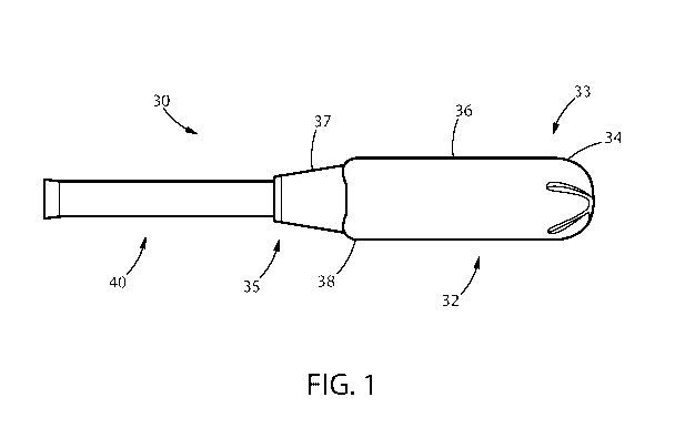
Figure 1 is a plan view showing an applicator 30. The applicator 30 comprises
an
insertion member or barrel 32 and a plunger 40. The applicator barrel 32 has
an insertion tip34
proximal a first end 33 and an opposing withdrawal end 35. The applicator
barrel region 36 is
adapted to contain a feminine care device such as, e.g., a tampon or
intravaginal incontinence
device (e.g., a pessary). The applicator withdrawal end 35 contains a grip
region 37 that may be
an indentation region. The grip region 37 may also be demarcated from the
barrel region 36,
such as, e.g., by one or more shoulder regions 38. Grip regions may comprise
three dimensional
surface elements that can protrude outward from the grip region.
CA 03013364 2018-07-31
WO 2017/151532 PCT/US2017/019809
13
Typically, tampons are constructed from an absorbent material, which has been
compressed in any or all of the width direction, the radial direction, and the
axial direction, in
order to provide a tampon, which is of a size and stability to allow insertion
within the vagina or
other body cavity. The tampon is preferably in a so-called 'self-sustaining'
form, e.g. it will tend
to retain its general shape and size, before use. This self-sustaining form
need not persist during
actual use of the tampon. The tampons herein are typically fluid expanding,
e.g. the tampon will
expand (or un-compress) upon contact with fluid such as bodily fluids.
The tampon has a top portion, having a topside or top (point) and a bottom
side or point,
both typically positioned at or forming the ends of the longitudinal axis of
the tampon. The top
portion of the tampon is typically the portion, which is positioned under the
petals, thus typically
the part from the top edge of the tube of the applicator to the top of the
inserter tip. Because the
inserter tip has preferably an opening at the top, part of the op portion of
the tampon may be
visible through this opening. The tampon has an insertion end and a withdrawal
end, whereby the
insertion end contains or is typically said top portion, whilst the withdrawal
end contains said
bottom side.
The tampon may be straight or non linear in shape, such as curved along the
longitudinal axis. If
the tampon is straight, the length of tampon is the longest distance between
the top portion and
bottom side and this is generally parallel to or even equal to the
longitudinal axis of the tampon.
The tampon may be serpentine as described in U.S. Pat. No. 6,824,536, filed
May 16, 2002,
.. entitled "Substantially Serpentine Shaped Tampon," issued to Randall, et
al. The tampon may be
shaped to have varying perimeters as described in U.S. Pat. No. 6,932,805,
filed May 16, 2002,
entitled "Shaped Tampon," issued to Kollwitz, et al. The tampon may be
discontinuous as
described in U.S. Pat. No. 8,597,267, filed April 18, 2007, entitled "Tampon
Having at Least One
Physical Discontinuity," issued to Noel, et al. The tampon may be shaped to
have improved
aspect ratios when compressed as described in U.S. Pat. No. 8,684,987, filed
February 8, 2007,
entitled "Self-Orienting Tampon Having Improved Aspect Ratio," issued to
Hasse, et al. The
tampon may have an assymetric insertion end as described in U.S. Pat. No.
8,216,202, filed
September 22, 2006, entitled "Tampon Having an Asymmetric Insertion End,"
issued to
Minoguchi, et al.
The tampon may be shaped to have a desired shape after expansion. An example
of this
is described in U.S. Pat. No. 6,953,456, entitled "Tampon Having An Oval Form
After
Expansion and Process For Producing the Same," issued to Fuchs, et al. The
tampons may be
CA 03013364 2018-07-31
WO 2017/151532 PCT/US2017/019809
14
compressed in a manner that allows for faster expansion and for increased
expansion in the width
dimension as described in U.S. Pat. No. 6,554,814, filed October 24, 2000,
entitled "Protection
Tampon and Method of Making," issued to Agyapong, et al.
The tampon has a width, which may vary in different portions of the tampon. If
the
tampon is straight, the transverse axis of the tampon is preferably
perpendicular to the
longitudinal axis and then the tampon width is typically perpendicular to the
length. Often, the
tampon is typically cylindrical, having preferably an endless sidewall or
endless longitudinal
side, preferably with a flat bottom side and with a rounded or dome-shaped top
portion; then, the
width of the tampon corresponds to the largest cylindrical cross-section
diameter, and the length
corresponds to the longest distance between the bottom side and the top of the
rounded portion.
The tampon may have a plurality of recessed portions as described in U.S. Pat.
No.
7,549,982, filed November 21, 2003, entitled "Tampon with Recessed Portions
Having Multiple
Widths," issued to Carlin. The tampon may contain adjacent wide and narrow
portions as
described in U.S. Pat. No. 6,939,340, filed May 21, 2004, entitled "Tampon
with Adjacent Wide
and Narrow Raised Portions," issued to Berges. The tampon may have one or more
longitudinal
grooves. The longitudinal grooves may be located in the insertion end, the
withdrawal end, or
both the withdrawal and insertion ends. The grooves may be offset as described
in U.S. Pat. No.
8,029,485, filed February 2, 2005, entitled "Tampon with Offset Grooves,"
issued to Jensen.
The tampon may be a non-layered, uniform structure, or it may be a laminar
structure
comprised of integral or discrete layers, or the tampon may have a folded
structure, or it may be
rolled, or any other of the structures which are known in the art. Generally,
the tampon herein has
to have a certain minimal rigidity, to facilitate the expulsion through the
film cap. An additional
patch may be located between the absorbent compressed member and the overwrap
as disclosed
in U.S. Pat. No. 8,048,053, filed April 14, 2008, entitled "Tampon Having an
Auxiliary Patch,"
issued to Minoguchi, et al.
The tampon may be constructed from a wide variety of liquid-absorbing
materials
commonly used in absorbent articles such as rayon, cotton, or comminuted wood
pulp which is
generally referred to as airfelt. Examples of other suitable absorbent
materials include creped
cellulose wadding; meltblown polymers including coform; chemically stiffened,
modified or
cross-linked cellulosic fibers; synthetic fibers such as crimped polyester
fibers; peat moss; foam;
tissue including tissue wraps and tissue laminates; or any equivalent material
or combinations of
CA 03013364 2018-07-31
WO 2017/151532 PCT/US2017/019809
materials, or mixtures of these. Preferred absorbent materials comprise
cotton, rayon (including
tri-lobal and conventional rayon fibers, and needle punched rayon), folded
tissues, woven
materials, nonwoven webs, synthetic and/or natural fibers. The tampon and any
component
thereof may comprise a single material or a combination of materials.
Acceptable types of rayon
5 include GALAXY Rayon (a tri-lobed rayon structure) available as 6140 Rayon
from Acordis
Fibers Ltd., of Hollywall, England and SARILLE L rayon (a round fiber rayon),
also available
from Acordis Fibers Ltd. Suitable cotton material includes, long fiber cotton,
short fiber cotton,
cotton linters, T-fiber cotton, card strips, and comber cotton. Preferably,
the cotton layers should
be a scoured & bleached cotton absorbent with a glycerin finish, a lemolin
finish, or other
10 suitable finish. Additionally, superabsorbent materials, such as
superabsorbent polymers or
absorbent gelling materials may be incorporated into the tampon.
The absorbent material may be surrounded with an overwrap. The overwrap may
have
liquid permeable material, if desired. Such materials may comprise rayon,
cotton, bicomponent
fibers, or other suitable natural or synthetic fibers known in the art. Rayon,
polyethylene,
15 polypropylene and blends of these are particularly suited for use as
cover material. he synthetic
fibers may include, but are not limited to, fibers such as polyester,
polyolefin, nylon,
polypropylene, polyethylene, polyacrylic, cellulose acetate or bicomponent
fibers. Natural fibers
may include, but are not limited to, those commonly known to be non-synthetic
and of natural
origin such as cotton and/or rayon. In general, the natural fibers may provide
ready absorption
and fluid wicking strength. The synthetic fibers may balance the capillary
strength of the blended
material, enabling the tampon to more readily slip against moist tissue,
resulting in easier
removal and hence removal comfort. The overwrap may be fluid wicking and may
extend
beyond the withdrawal end of the abosrobent material to form a skirt portion
as described in U.S.
Patent No. 6,840,927, filed November 16, 2001, entitled "Tampon with Fluid
Wicking Overwrap
With Skirt Portion," issued to Hasse, et al. Typically, the overwrap may
extend from about 2mm
to about 30 mm beyond the withdrawal end of the absorbent material.
The ratio of synthetic fibers to natural fibers may fall in the range of from
about 90:10 to about
30:70. Alternatively, the ratio of synthetic fibers to natural fibers may fall
in the range of from
about 70:30 to about 40:60. The synthetic fibers may have hydrophobic and/or
hydrophilic
surfaces. The synthetic fibers may be inherently hydrophilic, or may
preferably be treated to
provide such properties. The overwrap may comprise some level of hydrophobic
fibers as well,
as long as it does not significantly diminish the fluid wicking capacity of
the overwrap of the
tampon.
CA 03013364 2018-07-31
WO 2017/151532 PCT/US2017/019809
16
The blend of fibers forming the overwrap may be made by any number of
techniques. The
blends may be carded on webs. Commonly, carded webs that are hydroentangled,
thermally
bonded, and resin bonded all have application. In the latter case, the resin
bonding agent may be
used in place of the synthetic fibers as the method for tempering the
aggressiveness of the natural
fiber matrix. In this case, all natural fiber may be used with a significant
amount of synthetic
binder (10-30% by weight is common). Spunbond and meltblown processes,
combining synthetic
fibers extruded/spun onto/into a mat or carded web of natural fibers provide
other acceptable
techniques. The basis weight of the overwrap may fall into a range from about
10, 12 or 15 grams
per square meter to about 30, 40, 50 or 60 grams per square meter. The
materials for the tampon
may be formed into a fabric, web, or batt that is suitable for use in the
pledget by any suitable
process such as airlaying, carding, wetlaying, or other known techniques.
Fluid pervious overwrap may be made by any number of known techniques, but is
preferably an apertured nonwoven material. The nonwoven material may be made
by carding,
meltblowing, spunbonding, spunlacing, air laying, and the like. The apertures
may be zoned as
described in U.S. Pat. No. 7,994,387, filed on October 17, 2007, entitled
"Tampon having Zoned
Apertured Overwrap," issued to Minoguchi, et al. In one embodiment, the
apertures are formed
by forming a plurality of spaced, melt stabilized regions, and then ring-
rolling the web to stretch
the web and form apertures in the melt stabilized regions, as described in
U.S. Pat. Nos.
5,628,097 and 5,916,661, both of which are hereby incorporated by reference
herein.
It is desirable that the tampons are made in the absorbency ranges, which are
currently
required, by the United States Food and Drug Administration and corresponding
agencies of
many other governments, which regulate tampon absorbency. A "Super Plus"
absorbency
tampon should have a total absorbency as measured by the industry standard
Syngyna test of 12-
15 grams. A "Super" absorbency tampon should have a total absorbency as
measured by the
Syngyna test of 9-12 grams. A "Regular" absorbency tampon should have a
Syngyna absorbency
of 6-9 grams. A "Junior" absorbency tampon should have a Syngyna absorbency of
less than 6
grams. Providing a tampon which properly falls within these absorbency ranges
requires that the
total amount and type of absorbent material be controlled.
The tampon typically contains a withdrawal cord or string, which is generally
attached to
at least the withdrawal bottom side of the tampon. This may be any type of
withdrawal cord
known in the art, for example a generally braided (or twisted) withdrawal
cord. A conventional
type of withdrawal cord (in terms of thickness, material composition, etc.)
may be periodically
CA 03013364 2018-07-31
WO 2017/151532 PCT/US2017/019809
17
braided with a thicker slub of absorbent fibrous material, which acts as an
absorbing member, to
form a structure to be connected to the remaining of the tampon. In such an
embodiment, the
portion of the cord, which will act as the withdrawal cord, may be treated to
make it non-
absorbent or even hydrophobic. It may also be a withdrawal cord as described
in commonly
assigned and co-pending U.S. application Ser. No. 09/309,467, filed on May 10,
1999 in the
name of Taylor, et al. The tampon may contain any additional functional
ingredients, such as
antimicrobial agents, lubricants, antioxidants etc, as known in the art.
The tampon and applicator may be placed inside a wrapper or wrapper material.
By
'wrapper material' it is meant herein any material suitable to be used for
hygienically wrapping
tampons. Said wrapper material has two surfaces; the 'inner surface' is
directed towards the
wrapped tampon, whereas the 'outer surface' is aligned opposite to said inner
surface. Typically,
suitable wrapper materials for use herein are flexible polymeric films, having
a thickness of less
than 1 mm. Examples for wrapper materials suitable for use are polymeric films
made of
polyethylene, polypropylene, polyester, cellophane, polyamide, poly(vinyl
chloride), ethylene-
vinyl acetate copolymer and the like. Alternatively, heat-shrinkable films,
stretch films, pre-
stretched elastic material, or combinations thereof may be used to create the
wrapper. While not
limited to a given composition, preferred compositions of heat-shrinkable and
stretch films
comprise primarily polyolefins such as polyethylene and polypropylene, or
polyvinyl chloride.
Polystyrene and polyethylene-terephtalate (PET), although being not heat
sealable, are also
suitable for use. Wrappers consisting of those materials can be closed by
gluing with an adhesive.
Other generally occlusive materials include metallic foils, such as aluminium
foil. While
occlusive wrapper materials are often preferred, in other situations non-
occlusive or porous
materials can be used, such as nonwovens, wovens, scrims, meshes and papers.
Such non-
occlusive materials can be made occlusive by combinations such as by
lamination with or by
coating with occlusive material. In the case of cellulosic papers, examples
include lamination
with a polymeric film such as a polyolefinic composition or coating or
impregnation of the paper
with wax. The aforementioned materials can be coated with various chemical
compounds to
improve their barrier properties or the ability for sealing. The wrapper may
have a line of
weakness or an improved opening means as described in U.S. Pat. No. 6,955,
665, filed May 23,
2002, entitled "Tampon Wrapper with Improved Opening Means," issued to
Domeier, et al. or
U.S. Pat. No. 8,302,844, filed November 20, 2006, entitled "Wrapper Having a
Predetermined
Line of Weakness," issued to Mc Connell, et al.
CA 03013364 2018-07-31
WO 2017/151532 PCT/US2017/019809
18
Procedure to measure Onset Crystallization Temperature
Use a Differential Scanning Calorimeter (DSC) according to ASTM D3418. Follow
ASTM
D3418 to calibrate the DSC instrument and to prepare the sample. Using the
following
modifications, determine the onset temperature of the crystallization peak
(OTX) in C for the
sample using the following temperature program.
1. Equilibrate the sample at 200 C to erase previous thermal history.
2. Hold the sample at 200 C for 5 minutes.
3. Ramp the sample to 120 C at a rate of 50 C per minute.
4. Hold the sample at 120 C for 1 minute to stabilize the temperature.
5. Ramp the sample to 90 C at a rate of 2 C per minute.
For each sample, use the DSC software to determine the intersection of two
asymptotes, as
shown in Fig. 2. Record the onset temperature crystallization peak (OTX) to
the nearest 0.01
C. Calculate OTX for the 3 replicates and report the average OTX to the
nearest 0.01 C.
Tampon Applicator Opacity, Color and Color Masking
All opacity, color and color masking measurements are made using a 0 /45
spectrophotometer
suitable for making standard CIE L*a*b* color measurements (e.g. Hunter
Labscan XE
spectrophotometer, Hunter Associates Laboratory Inc., Reston VA or
equivalent). The diameter
of the instrument's measurement port should be smaller than the dimensions of
the sample.
Analyses are performed in a room controlled at about 23 C 2 C and 50% 2%
relative humidity.
Samples are conditioned at the same condition for 2 hours before testing.
Samples are prepared by first removing and discarding the pledget and plunger
from the barrel.
Using an Exacto knife, the finger-grip portion as well as the petal portion of
the barrel is
removed. The barrel is then cut open with a longitudinal slice from the petal
end to the finger-
grip end. The sample should be free from creases, wrinkles, tears, and other
obvious defects.
For all testing, the sample is positioned so that the outer surface of the
applicator as it is
converted will be the surface of the sample that faces the orifice of the
instrument sample port.
The sample is positioned so that it lies flat and the longitudinal centerline
between the petal and
finger-grip ends is centered over the spectrophotometer orifice.
Opacity is measured by contrast ratio. Calibrate the instrument per the vendor
instructions using
the standard black and white tiles provided by the vendor. Set the
spectrophotometer to use the
CIE XYZ color space, with a D65 standard illumination, a 10 observer and the
UV filter set to
CA 03013364 2018-07-31
WO 2017/151532 PCT/US2017/019809
19
nominal. Place the sample flat against the instrument's measurement port and
then place the
white standard tile onto the opposing surface of the sample such that it
completely covers the
measurement port. Take a reading for XYZ and record to 0.01 units. Without
moving the
sample, remove the white tile and replace it with the black standard tile.
Take a second reading
for XYZ and record to 0.01 units. Repeat this procedure for a total of three
(3) replicate samples.
Opacity is calculated by dividing the Y value measured using the black tile as
backing, divided
by the Y value measured using the white tile as backing, then multiplying the
ratio by 100.
Record the opacity value to the nearest 0.01%. Calculate opacity for the 3
replicates and report
the average opacity to the nearest 0.01%.
The color scale values, utilized herein to define the darkness/lightness of
the tampon applicator
material according to the present invention, is the widely accepted CIE LAB
scale.
Measurements are made on the sample directly after measuring the opacity.
Set the
spectrophotometer to use the CIE LAB color space, with a D65 standard
illumination, a 100
observer and the UV filter set to nominal. Color measurements are made on the
sample with the
white standard tile as backing. Place the sample flat against the instrument's
measurement port
and then place the white standard tile onto the opposing surface of the sample
such that it
completely covers the measurement port. Take a reading for L*, a*, b* and
record to 0.01 units.
Repeat this procedure for a total of three (3) replicate samples. Report the
average L*, a*, b*
values to the nearest 0.01 units.
The extent of the applicator to mask the color red is measured by comparing
the red color
difference between a standard transparent red tile measured with the standard
white tile as
backing and the standard transparent red tile with the applicator sample and
the standard white
tile as backing. A transparent red tile, such as Acrylite (FF) dark red
3M031GT extruded sheet
Pantone matched for red color 202 T (plexiglass #2423, 3.175 mm + 0.3 mm
thick, available
from ePlastics, a Ridout Plastics Company, San Diego, California), is used as
the standard
transparent red tile. Set the spectrophotometer to use the CIE LAB color
space, with a D65
standard illumination, a 10 observer and the UV filter set to nominal. Center
the standard red
transparent tile over the instrument's measurement port and then place the
white standard tile
onto the opposing surface such that it completely covers the measurement port.
Take a reading
for L*, a*, b* and record to 0.01 units. Remove the white standard tile. Place
the sample flat
against the standard red transparent tile such that the sample is centered
over the instrument's
measurement port and then place the white standard tile onto the opposing
surface of the sample
such that it completely covers the measurement port. Take a reading for L*,
a*, b* and record to
CA 03013364 2018-07-31
WO 2017/151532 PCT/US2017/019809
0.01 units. Repeat this procedure for a total of three (3) replicate samples.
Report the average
L*, a*, b* values to the nearest 0.01 units.
The dimensions and values disclosed herein are not to be understood as being
strictly
5 limited to the exact numerical values recited. Instead, unless otherwise
specified, each such
dimension is intended to mean both the recited value and a functionally
equivalent range
surrounding that value. For example, a dimension disclosed as "40 mm" is
intended to mean
"about 40 mm."
All documents cited in the Detailed Description of the Invention are, in
relevant part,
10 incorporated herein by reference; the citation of any document is not to
be construed as an
admission that it is prior art with respect to the present invention. To the
extent that any meaning
or definition of a term in this document conflicts with any meaning or
definition of the same term
in a document incorporated by reference, the meaning or definition assigned to
that term in this
document shall govern.
15 While particular embodiments of the present invention have been
illustrated and
described, it would be obvious to those skilled in the art that various other
changes and
modifications can be made without departing from the spirit and scope of the
invention. It is
therefore intended to cover in the appended claims all such changes and
modifications that are
within the scope of this invention.